
Product Manual
Pulsar
®
XT.2 SAS
100647497
Rev. B
June 2011
Standard Models
ST400FX0002
ST200FX0002
ST100FX0002
Self-Encrypting Drive Models
ST400FX0012

Revision history
© 2011 Seagate Technology LLC. All rights reserved.
Publication number: 100647497, Rev. B June 2011
Seagate, Seagate Technology and the Wave logo are registered trademarks of Seagate Technology
LLC in the United States and/or other countries. Pulsar and SeaTools are either trademarks or regis
-
tered trademarks of Seagate Technology LLC or one of its affiliated companies in the United States
and/or other countries. All other trademarks or registered trademarks are the property of their
respective owners.
No part of this publication may be reproduced in any form without written permission of Seagate
Technology LLC. Call 877-PUB-TEK1 (877-782-8351) to request permission.
One gigabyte, or GB, equals one billion bytes and one terabyte, or TB, equals one trillion bytes.
Your computer's operating system may use a different standard of measurement and report a lower
capacity. In addition, some of the listed capacity is used for formatting and other functions, and thus
will not be available for data storage. Seagate reserves the right to change, without notice, product
offerings or specifications.
Revision Date Sheets affected or comments
Rev. A 03/16/11 Initial release.
Rev. B 06/01/11 34. (7mm weight correction)

Pulsar XT.2 SAS Product Manual, Rev. B i
Contents
1.0 Seagate Technology support services. . . . . . . . . . . . . . . . . . . . . . . . . . . . . . . . . . . . . . . . . . . . . 1
2.0 Scope. . . . . . . . . . . . . . . . . . . . . . . . . . . . . . . . . . . . . . . . . . . . . . . . . . . . . . . . . . . . . . . . . . . . . . . . 2
3.0 Applicable standards and reference documentation . . . . . . . . . . . . . . . . . . . . . . . . . . . . . . . . . 3
3.1 Standards . . . . . . . . . . . . . . . . . . . . . . . . . . . . . . . . . . . . . . . . . . . . . . . . . . . . . . . . . . . . . . 3
3.1.1 Electromagnetic compatibility. . . . . . . . . . . . . . . . . . . . . . . . . . . . . . . . . . . . . . . . 3
3.1.2 Electromagnetic compliance . . . . . . . . . . . . . . . . . . . . . . . . . . . . . . . . . . . . . . . . 4
3.1.3 European Union Restriction of Hazardous Substances (RoHS) . . . . . . . . . . . . . 4
3.1.4 China Restriction of Hazardous Substances (RoHS) Directive . . . . . . . . . . . . . . 5
3.2 Reference documents . . . . . . . . . . . . . . . . . . . . . . . . . . . . . . . . . . . . . . . . . . . . . . . . . . . . . 5
4.0 General description . . . . . . . . . . . . . . . . . . . . . . . . . . . . . . . . . . . . . . . . . . . . . . . . . . . . . . . . . . . . 6
4.1 Standard features . . . . . . . . . . . . . . . . . . . . . . . . . . . . . . . . . . . . . . . . . . . . . . . . . . . . . . . . 6
4.2 Media description . . . . . . . . . . . . . . . . . . . . . . . . . . . . . . . . . . . . . . . . . . . . . . . . . . . . . . . . 7
4.3 Performance . . . . . . . . . . . . . . . . . . . . . . . . . . . . . . . . . . . . . . . . . . . . . . . . . . . . . . . . . . . . 7
4.4 Reliability . . . . . . . . . . . . . . . . . . . . . . . . . . . . . . . . . . . . . . . . . . . . . . . . . . . . . . . . . . . . . . . 7
4.5 Formatted capacities . . . . . . . . . . . . . . . . . . . . . . . . . . . . . . . . . . . . . . . . . . . . . . . . . . . . . . 8
4.6 Programmable drive capacity . . . . . . . . . . . . . . . . . . . . . . . . . . . . . . . . . . . . . . . . . . . . . . . 8
4.7 Factory-installed options . . . . . . . . . . . . . . . . . . . . . . . . . . . . . . . . . . . . . . . . . . . . . . . . . . . 8
4.8 Thin Provisioning. . . . . . . . . . . . . . . . . . . . . . . . . . . . . . . . . . . . . . . . . . . . . . . . . . . . . . . . . 9
4.8.1 Logical Block Provisioning . . . . . . . . . . . . . . . . . . . . . . . . . . . . . . . . . . . . . . . . . . 9
4.8.2 Thin Provisioning capabilities. . . . . . . . . . . . . . . . . . . . . . . . . . . . . . . . . . . . . . . . 9
4.8.3 UNMAP . . . . . . . . . . . . . . . . . . . . . . . . . . . . . . . . . . . . . . . . . . . . . . . . . . . . . . . . 9
4.8.4 FORMAT UNIT command . . . . . . . . . . . . . . . . . . . . . . . . . . . . . . . . . . . . . . . . . . 9
4.8.5 Protection Information (PI) and Security (SED) . . . . . . . . . . . . . . . . . . . . . . . . . . 9
5.0 Performance characteristics . . . . . . . . . . . . . . . . . . . . . . . . . . . . . . . . . . . . . . . . . . . . . . . . . . . . 11
5.1 Internal drive characteristics . . . . . . . . . . . . . . . . . . . . . . . . . . . . . . . . . . . . . . . . . . . . . . . 11
5.2 Performance characteristics . . . . . . . . . . . . . . . . . . . . . . . . . . . . . . . . . . . . . . . . . . . . . . . 11
5.2.1 Access time . . . . . . . . . . . . . . . . . . . . . . . . . . . . . . . . . . . . . . . . . . . . . . . . . . . . 11
5.2.2 FORMAT UNIT command execution time for 512-byte LBA’s (minutes). . . . . . 12
5.2.3 Performance. . . . . . . . . . . . . . . . . . . . . . . . . . . . . . . . . . . . . . . . . . . . . . . . . . . . 12
5.3 Start/stop time . . . . . . . . . . . . . . . . . . . . . . . . . . . . . . . . . . . . . . . . . . . . . . . . . . . . . . . . . . 13
5.4 Cache control . . . . . . . . . . . . . . . . . . . . . . . . . . . . . . . . . . . . . . . . . . . . . . . . . . . . . . . . . . 13
5.4.1 Caching write data . . . . . . . . . . . . . . . . . . . . . . . . . . . . . . . . . . . . . . . . . . . . . . . 13
6.0 Reliability specifications . . . . . . . . . . . . . . . . . . . . . . . . . . . . . . . . . . . . . . . . . . . . . . . . . . . . . . . 14
6.1 Error rates . . . . . . . . . . . . . . . . . . . . . . . . . . . . . . . . . . . . . . . . . . . . . . . . . . . . . . . . . . . . . 14
6.1.1 Unrecoverable Errors. . . . . . . . . . . . . . . . . . . . . . . . . . . . . . . . . . . . . . . . . . . . . 15
6.1.2 Interface errors. . . . . . . . . . . . . . . . . . . . . . . . . . . . . . . . . . . . . . . . . . . . . . . . . . 15
6.2 Endurance Management . . . . . . . . . . . . . . . . . . . . . . . . . . . . . . . . . . . . . . . . . . . . . . . . . . 15
6.2.1 Wear Leveling . . . . . . . . . . . . . . . . . . . . . . . . . . . . . . . . . . . . . . . . . . . . . . . . . . 15
6.2.2 Garbage Collection . . . . . . . . . . . . . . . . . . . . . . . . . . . . . . . . . . . . . . . . . . . . . . 15
6.2.3 Write Amplification . . . . . . . . . . . . . . . . . . . . . . . . . . . . . . . . . . . . . . . . . . . . . . . 15
6.2.4 UNMAP . . . . . . . . . . . . . . . . . . . . . . . . . . . . . . . . . . . . . . . . . . . . . . . . . . . . . . . 15
6.2.5 Data Retention. . . . . . . . . . . . . . . . . . . . . . . . . . . . . . . . . . . . . . . . . . . . . . . . . . 16
6.2.6 Lifetime Endurance Management . . . . . . . . . . . . . . . . . . . . . . . . . . . . . . . . . . . 16
6.3 Reliability and service . . . . . . . . . . . . . . . . . . . . . . . . . . . . . . . . . . . . . . . . . . . . . . . . . . . . 16
6.3.1 Annualized Failure Rate (AFR) and Mean Time Between Failure (MTBF) . . . . 16
6.3.2 Preventive maintenance. . . . . . . . . . . . . . . . . . . . . . . . . . . . . . . . . . . . . . . . . . . 16
6.3.3 Hot plugging the drive . . . . . . . . . . . . . . . . . . . . . . . . . . . . . . . . . . . . . . . . . . . . 16
6.3.4 S.M.A.R.T. . . . . . . . . . . . . . . . . . . . . . . . . . . . . . . . . . . . . . . . . . . . . . . . . . . . . . 17
6.3.5 Thermal monitor. . . . . . . . . . . . . . . . . . . . . . . . . . . . . . . . . . . . . . . . . . . . . . . . . 18
6.3.6 Drive Self Test (DST). . . . . . . . . . . . . . . . . . . . . . . . . . . . . . . . . . . . . . . . . . . . . 19

ii Pulsar XT.2 SAS Product Manual, Rev. B
6.3.7 Product warranty . . . . . . . . . . . . . . . . . . . . . . . . . . . . . . . . . . . . . . . . . . . . . . . . 21
7.0 Physical/electrical specifications . . . . . . . . . . . . . . . . . . . . . . . . . . . . . . . . . . . . . . . . . . . . . . . . 22
7.1 Power specifications . . . . . . . . . . . . . . . . . . . . . . . . . . . . . . . . . . . . . . . . . . . . . . . . . . . . . 22
7.1.1 Power consumption . . . . . . . . . . . . . . . . . . . . . . . . . . . . . . . . . . . . . . . . . . . . . . 22
7.2 AC power requirements . . . . . . . . . . . . . . . . . . . . . . . . . . . . . . . . . . . . . . . . . . . . . . . . . . . 22
7.3 DC power requirements . . . . . . . . . . . . . . . . . . . . . . . . . . . . . . . . . . . . . . . . . . . . . . . . . . 23
7.3.1 Conducted noise immunity. . . . . . . . . . . . . . . . . . . . . . . . . . . . . . . . . . . . . . . . . 26
7.3.2 Power sequencing . . . . . . . . . . . . . . . . . . . . . . . . . . . . . . . . . . . . . . . . . . . . . . . 26
7.3.3 Current profiles. . . . . . . . . . . . . . . . . . . . . . . . . . . . . . . . . . . . . . . . . . . . . . . . . . 26
7.4 Power dissipation. . . . . . . . . . . . . . . . . . . . . . . . . . . . . . . . . . . . . . . . . . . . . . . . . . . . . . . . 28
7.5 Environmental limits. . . . . . . . . . . . . . . . . . . . . . . . . . . . . . . . . . . . . . . . . . . . . . . . . . . . . . 29
7.5.1 Temperature. . . . . . . . . . . . . . . . . . . . . . . . . . . . . . . . . . . . . . . . . . . . . . . . . . . . 29
7.5.2 Relative humidity . . . . . . . . . . . . . . . . . . . . . . . . . . . . . . . . . . . . . . . . . . . . . . . . 30
7.5.3 Effective altitude (sea level) . . . . . . . . . . . . . . . . . . . . . . . . . . . . . . . . . . . . . . . . 30
7.5.4 Shock and vibration . . . . . . . . . . . . . . . . . . . . . . . . . . . . . . . . . . . . . . . . . . . . . . 30
7.5.5 Air cleanliness . . . . . . . . . . . . . . . . . . . . . . . . . . . . . . . . . . . . . . . . . . . . . . . . . . 32
7.5.6 Corrosive environment . . . . . . . . . . . . . . . . . . . . . . . . . . . . . . . . . . . . . . . . . . . . 32
7.5.7 Electromagnetic susceptibility . . . . . . . . . . . . . . . . . . . . . . . . . . . . . . . . . . . . . . 32
7.6 Mechanical specifications . . . . . . . . . . . . . . . . . . . . . . . . . . . . . . . . . . . . . . . . . . . . . . . . . 33
8.0 About self-encrypting drives . . . . . . . . . . . . . . . . . . . . . . . . . . . . . . . . . . . . . . . . . . . . . . . . . . . . 35
8.1 Data encryption . . . . . . . . . . . . . . . . . . . . . . . . . . . . . . . . . . . . . . . . . . . . . . . . . . . . . . . . . 35
8.2 Controlled access. . . . . . . . . . . . . . . . . . . . . . . . . . . . . . . . . . . . . . . . . . . . . . . . . . . . . . . . 35
8.2.1 Admin SP . . . . . . . . . . . . . . . . . . . . . . . . . . . . . . . . . . . . . . . . . . . . . . . . . . . . . . 35
8.2.2 Locking SP . . . . . . . . . . . . . . . . . . . . . . . . . . . . . . . . . . . . . . . . . . . . . . . . . . . . . 36
8.2.3 Default password . . . . . . . . . . . . . . . . . . . . . . . . . . . . . . . . . . . . . . . . . . . . . . . . 36
8.3 Random number generator (RNG). . . . . . . . . . . . . . . . . . . . . . . . . . . . . . . . . . . . . . . . . . . 36
8.4 Drive locking. . . . . . . . . . . . . . . . . . . . . . . . . . . . . . . . . . . . . . . . . . . . . . . . . . . . . . . . . . . . 36
8.5 Data bands. . . . . . . . . . . . . . . . . . . . . . . . . . . . . . . . . . . . . . . . . . . . . . . . . . . . . . . . . . . . . 36
8.6 Cryptographic erase. . . . . . . . . . . . . . . . . . . . . . . . . . . . . . . . . . . . . . . . . . . . . . . . . . . . . . 37
8.7 Authenticated firmware download . . . . . . . . . . . . . . . . . . . . . . . . . . . . . . . . . . . . . . . . . . . 37
8.8 Power requirements. . . . . . . . . . . . . . . . . . . . . . . . . . . . . . . . . . . . . . . . . . . . . . . . . . . . . . 37
8.9 Supported commands . . . . . . . . . . . . . . . . . . . . . . . . . . . . . . . . . . . . . . . . . . . . . . . . . . . . 37
8.10 RevertSP . . . . . . . . . . . . . . . . . . . . . . . . . . . . . . . . . . . . . . . . . . . . . . . . . . . . . . . . . . . . . . 37
9.0 Defect and error management. . . . . . . . . . . . . . . . . . . . . . . . . . . . . . . . . . . . . . . . . . . . . . . . . . . 38
9.1 Drive internal defects/errors. . . . . . . . . . . . . . . . . . . . . . . . . . . . . . . . . . . . . . . . . . . . . . . . 38
9.2 Drive error recovery procedures . . . . . . . . . . . . . . . . . . . . . . . . . . . . . . . . . . . . . . . . . . . . 39
9.3 SAS system errors. . . . . . . . . . . . . . . . . . . . . . . . . . . . . . . . . . . . . . . . . . . . . . . . . . . . . . . 39
9.4 Background Media Scan . . . . . . . . . . . . . . . . . . . . . . . . . . . . . . . . . . . . . . . . . . . . . . . . . . 39
9.5 Auto-Reallocation. . . . . . . . . . . . . . . . . . . . . . . . . . . . . . . . . . . . . . . . . . . . . . . . . . . . . . . . 39
9.6 Protection Information (PI). . . . . . . . . . . . . . . . . . . . . . . . . . . . . . . . . . . . . . . . . . . . . . . . . 40
9.6.1 Levels of PI. . . . . . . . . . . . . . . . . . . . . . . . . . . . . . . . . . . . . . . . . . . . . . . . . . . . . 40
9.6.2 Setting and determining the current Type Level. . . . . . . . . . . . . . . . . . . . . . . . . 40
9.6.3 Identifying a Protection Information drive. . . . . . . . . . . . . . . . . . . . . . . . . . . . . . 40
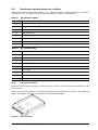
10.0 Installation. . . . . . . . . . . . . . . . . . . . . . . . . . . . . . . . . . . . . . . . . . . . . . . . . . . . . . . . . . . . . . . . . . . 41
10.1 Drive orientation. . . . . . . . . . . . . . . . . . . . . . . . . . . . . . . . . . . . . . . . . . . . . . . . . . . . . . . . . 41
10.2 Cooling. . . . . . . . . . . . . . . . . . . . . . . . . . . . . . . . . . . . . . . . . . . . . . . . . . . . . . . . . . . . . . . . 42
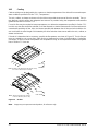
10.3 Drive mounting. . . . . . . . . . . . . . . . . . . . . . . . . . . . . . . . . . . . . . . . . . . . . . . . . . . . . . . . . . 43
10.4 Grounding . . . . . . . . . . . . . . . . . . . . . . . . . . . . . . . . . . . . . . . . . . . . . . . . . . . . . . . . . . . . . 43
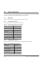
11.0 Interface requirements . . . . . . . . . . . . . . . . . . . . . . . . . . . . . . . . . . . . . . . . . . . . . . . . . . . . . . . . . 44
11.1 SAS features . . . . . . . . . . . . . . . . . . . . . . . . . . . . . . . . . . . . . . . . . . . . . . . . . . . . . . . . . . . 44
11.1.1 Task management functions . . . . . . . . . . . . . . . . . . . . . . . . . . . . . . . . . . . . . . . 44
11.1.2 Task management responses. . . . . . . . . . . . . . . . . . . . . . . . . . . . . . . . . . . . . . 44

Pulsar XT.2 SAS Product Manual, Rev. B iii
11.2 Dual port support. . . . . . . . . . . . . . . . . . . . . . . . . . . . . . . . . . . . . . . . . . . . . . . . . . . . . . . . 45
11.3 SCSI commands supported. . . . . . . . . . . . . . . . . . . . . . . . . . . . . . . . . . . . . . . . . . . . . . . . 46
11.3.1 INQUIRY data . . . . . . . . . . . . . . . . . . . . . . . . . . . . . . . . . . . . . . . . . . . . . . . . . . 50
11.3.2 MODE SENSE data. . . . . . . . . . . . . . . . . . . . . . . . . . . . . . . . . . . . . . . . . . . . . . 50
11.4 Miscellaneous operating features and conditions . . . . . . . . . . . . . . . . . . . . . . . . . . . . . . . 55
11.4.1 SAS physical interface. . . . . . . . . . . . . . . . . . . . . . . . . . . . . . . . . . . . . . . . . . . . 55
11.4.2 Physical characteristics . . . . . . . . . . . . . . . . . . . . . . . . . . . . . . . . . . . . . . . . . . . 58
11.4.3 Connector requirements. . . . . . . . . . . . . . . . . . . . . . . . . . . . . . . . . . . . . . . . . . . 58
11.4.4 Electrical description . . . . . . . . . . . . . . . . . . . . . . . . . . . . . . . . . . . . . . . . . . . . . 58
11.4.5 Pin descriptions . . . . . . . . . . . . . . . . . . . . . . . . . . . . . . . . . . . . . . . . . . . . . . . . . 58
11.4.6 SAS transmitters and receivers . . . . . . . . . . . . . . . . . . . . . . . . . . . . . . . . . . . . . 59
11.4.7 Power. . . . . . . . . . . . . . . . . . . . . . . . . . . . . . . . . . . . . . . . . . . . . . . . . . . . . . . . . 59
11.5 Signal characteristics. . . . . . . . . . . . . . . . . . . . . . . . . . . . . . . . . . . . . . . . . . . . . . . . . . . . . 59
11.5.1 Ready LED Out . . . . . . . . . . . . . . . . . . . . . . . . . . . . . . . . . . . . . . . . . . . . . . . . . 59
11.5.2 Differential signals . . . . . . . . . . . . . . . . . . . . . . . . . . . . . . . . . . . . . . . . . . . . . . . 60
11.6 SAS-2 Specification compliance . . . . . . . . . . . . . . . . . . . . . . . . . . . . . . . . . . . . . . . . . . . . 60
11.7 Additional information . . . . . . . . . . . . . . . . . . . . . . . . . . . . . . . . . . . . . . . . . . . . . . . . . . . . 60

iv Pulsar XT.2 SAS Product Manual, Rev. B

Pulsar XT.2 SAS Product Manual, Rev. B v
List of Figures
Figure 1. Current profiles for 400GB models . . . . . . . . . . . . . . . . . . . . . . . . . . . . . . . . . . . . . . . . . . . . 26
Figure 2. Current profiles for 200GB models . . . . . . . . . . . . . . . . . . . . . . . . . . . . . . . . . . . . . . . . . . . . . 27
Figure 3. Current profiles for 100GB models . . . . . . . . . . . . . . . . . . . . . . . . . . . . . . . . . . . . . . . . . . . . . 27
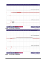
Figure 4. 400GB (at 6Gb) DC current and power vs. input/output operations per second . . . . . . . . . . 28
Figure 5. 200GB (at 6Gb) DC current and power vs. input/output operations per second . . . . . . . . . . 28
Figure 6. 100GB (at 6Gb) DC current and power vs. input/output operations per second . . . . . . . . . . 29
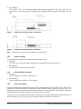
Figure 7. Temperature check point location - 15mm drives. . . . . . . . . . . . . . . . . . . . . . . . . . . . . . . . . . 30
Figure 8. Temperature check point location - 7mm drives. . . . . . . . . . . . . . . . . . . . . . . . . . . . . . . . . . . 30
Figure 9. Recommended mounting . . . . . . . . . . . . . . . . . . . . . . . . . . . . . . . . . . . . . . . . . . . . . . . . . . . . 31
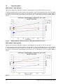
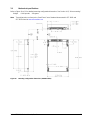
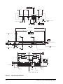
Figure 10. Mounting configuration dimensions (400GB models). . . . . . . . . . . . . . . . . . . . . . . . . . . . . . . 33
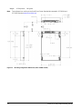
Figure 11. Mounting configuration dimensions (200 & 100GB models). . . . . . . . . . . . . . . . . . . . . . . . . . 34
Figure 12. Physical interface . . . . . . . . . . . . . . . . . . . . . . . . . . . . . . . . . . . . . . . . . . . . . . . . . . . . . . . . . . 41
Figure 13. Air flow . . . . . . . . . . . . . . . . . . . . . . . . . . . . . . . . . . . . . . . . . . . . . . . . . . . . . . . . . . . . . . . . . . 42
Figure 14. Physical interface . . . . . . . . . . . . . . . . . . . . . . . . . . . . . . . . . . . . . . . . . . . . . . . . . . . . . . . . . . 55
Figure 15. SAS device plug dimensions . . . . . . . . . . . . . . . . . . . . . . . . . . . . . . . . . . . . . . . . . . . . . . . . . 56
Figure 16. SAS device plug dimensions (detail) . . . . . . . . . . . . . . . . . . . . . . . . . . . . . . . . . . . . . . . . . . . 57
Figure 17. SAS transmitters and receivers . . . . . . . . . . . . . . . . . . . . . . . . . . . . . . . . . . . . . . . . . . . . . . . 59


Pulsar XT.2 SAS Product Manual, Rev. B 1
1.0 Seagate Technology support services
SEAGATE ONLINE SUPPORT and SERVICES
For information regarding products and services, visit http://www.seagate.com/www/en-us/about/contact_us/
Available services include:
Presales & Technical support
Global Support Services telephone numbers & business hours
Authorized Service Centers
For information regarding Warranty Support, visit
http://www.sea
gate.com/www/en-us/support/warranty_&_returns_assistance
For information regarding Data Recovery Services, visit http://www.i365.com
For Seagate OEM & Distribution partner portal, visit https://direct.seagate.com/portal/system
For Seagate reseller portal, visit http://spp.seagate.com

2 Pulsar XT.2 SAS Product Manual, Rev. B
2.0 Scope
This manual describes Seagate Technology
®
LLC, Pulsar
®
XT.2 SAS (Serial Attached SCSI) drives.
Pulsar XT.2 drives support the SAS Protocol specifications to the extent described in this manual. The SAS
Interface Manual (part number 100293071) describes the general SAS characteristics of this and other Sea-
gate SAS drives. The Self-Encrypting Drive Reference Manual, part number 100515636, describes the inter-
face, general operation, and security features available on Self-Encrypting Drive models.
Product data communicated in this manual is specific only to the model numbers listed in this manual. The data
listed in this manual may not be predictive of future generation specifications or requirements. If you are
designing a system which will use one of the models listed or future generation products and need further
assistance, please contact your Field Applications Engineer (FAE) or our global support services group as
shown in Section 1.0.
Unless otherwise stated, the information in this manual applies to standard and Self-Encrypting Drive models.
Note. Previous generations of Seagate Self-Encrypting Drive models were called Full Disk Encryption
(FDE) models before a differentiation between drive-based encryption and other forms of encryp
-
tion was necessary.
Note. The Self-Encrypting Drive models indicated on the cover of this product manual have provisions for
“Security of Data at Rest” based on the standards defined by the Trusted Computing Group (see
www.trustedcomputinggroup.org).
Standard models Standard SED models
ST400FX0002 ST400FX0012
ST200FX0002
ST100FX0002

Pulsar XT.2 SAS Product Manual, Rev. B 3
3.0 Applicable standards and reference documentation
The drives documented in this manual have been developed as system peripherals to the highest standards of
design and construction. The drives depend on host equipment to provide adequate power and environment
for optimum performance and compliance with applicable industry and governmental regulations. Special
attention must be given in the areas of safety, power distribution, shielding, audible noise control, and temper-
ature regulation. In particular, the drives must be securely mounted to guarantee the specified performance
characteristics. Mounting by bottom holes must meet the requirements of Section 10.3.
3.1 Standards
The Pulsar XT.2 family complies with Seagate standards as noted in the appropriate sections of this manual
and the Seagate SAS Interface Manual, part number 100293071.
The drives are recognized in accordance with UL 60950 and CSA 60950 as tested by UL(CSA) and EN60950
as tested by TUV.
The security features of Self-Encrypting Drive models are based on the “TCG Storage Architecture Core Spec-
ification” and the “TCG Storage Workgroup Security Subsystem Class: Enterprise_A” specification with addi-
tional vendor-unique features as noted in this product manual.
3.1.1 Electromagnetic compatibility
The drive, as delivered, is designed for system integration and installation into a suitable enclosure prior to
use. The drive is supplied as a subassembly and is not subject to Subpart B of Part 15 of the FCC Rules and
Regulations nor the Radio Interference Regulations of the Canadian Department of Communications.
The design characteristics of the drive serve to minimize radiation when installed in an enclosure that provides
reasonable shielding. The drive is capable of meeting the Class B limits of the FCC Rules and Regulations of
the Canadian Department of Communications when properly packaged; however, it is the user’s responsibility
to assure that the drive meets the appropriate EMI requirements in their system. Shielded I/O cables may be
required if the enclosure does not provide adequate shielding. If the I/O cables are external to the enclosure,
shielded cables should be used, with the shields grounded to the enclosure and to the host controller.
3.1.1.1 Electromagnetic susceptibility
As a component assembly, the drive is not required to meet any susceptibility performance requirements. It is
the responsibility of those integrating the drive within their systems to perform those tests required and design
their system to ensure that equipment operating in the same system as the drive or external to the system
does not adversely affect the performance of the drive. See Tables 8 through 10, DC power requirements.

4 Pulsar XT.2 SAS Product Manual, Rev. B
3.1.2 Electromagnetic compliance
Seagate uses an independent laboratory to confirm compliance with the directives/standards for CE Marking
and C-Tick Marking. The drive was tested in a representative system for typical applications. The selected sys-
tem represents the most popular characteristics for test platforms. The system configurations include:
• Typical current use microprocessor
• Keyboard
• Monitor/display
• Printer
•Mouse
Although the test system with this Seagate model complies with the directives/standards, we cannot guarantee
that all systems will comply. The computer manufacturer or system integrator shall confirm EMC compliance
and provide the appropriate marking for their product.
Electromagnetic compliance for the European Union
If this model has the CE Marking it complies with the European Union requirements of the Electromagnetic
Compatibility Directive 2004/108/EC as put into place on 20 July 2007.
Australian C-Tick
If this model has the C-Tick Marking it complies with the Australia/New Zealand Standard AS/NZ CISPR22 and
meets the Electromagnetic Compatibility (EMC) Framework requirements of Australia’s Spectrum Manage-
ment Agency (SMA).
Korean KCC
If these drives have the Korean Communications Commission (KCC) logo, they comply with KN22 and
KN61000.
Taiwanese BSMI
If this model has the Taiwanese certification mark then it complies with Chinese National Standard, CNS13438.
3.1.3 European Union Restriction of Hazardous Substances (RoHS)
The European Union Restriction of Hazardous Substances (RoHS) Directive restricts the presence of chemical
substances, including Lead (Pb), in electronic products effective July 2006.
A number of parts and materials in Seagate products are procured from external suppliers. We rely on the rep-
resentations of our suppliers regarding the presence of RoHS substances in these parts and materials. Our
supplier contracts require compliance with our chemical substance restrictions, and our suppliers document
their compliance with our requirements by providing material content declarations for all parts and materials for
the drives documented in this publication. Current supplier declarations include disclosure of the inclusion of
any RoHS-regulated substance in such parts or materials.
Seagate also has internal systems in place to ensure ongoing compliance with the RoHS Directive and all laws
and regulations which restrict chemical content in electronic products. These systems include standard operat-
ing procedures that ensure that restricted substances are not utilized in our manufacturing operations, labora-
tory analytical validation testing, and an internal auditing process to ensure that all standard operating
procedures are complied with.

Pulsar XT.2 SAS Product Manual, Rev. B 5
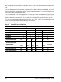
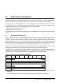
3.1.4 China Restriction of Hazardous Substances (RoHS) Directive
This product has an Environmental Protection Use Period (EPUP) of 20 years. The following
table contains information mandated by China's "Marking Requirements for Control of Pollution
Caused by Electronic Information Products" Standard.
"O" indicates the hazardous and toxic substance content of the part (at the homogenous material level) is lower
than the threshold defined by the China RoHS MCV Standard.
"X" indicates the hazardous and toxic substance content of the part (at the homogenous material level) is over
the threshold defined by the China RoHS MCV Standard.
3.2 Reference documents
SCSI Commands Reference Manual Seagate part number: 100293068
SAS Interface Manual Seagate p
art number: 100293071
ANSI SAS Documents
SFF-8223 2.5” Drive Form Factor with Serial Connector
SFF-8460 HSS Backplane Design Guidelines
SFF-8470 Multi Lane Copper Connector
SFF-8482 SAS Plug Connector
ANSI INCITS.xxx Serial Attached SCS
I (SAS-2) Standard (T10/1760-D)
ISO/IEC 14776-xxx SCSI Architecture Model-3 (SAM-4) Standard (T10/1683-D)
ISO/IEC 14776-xxx SCSI Primary Commands-3 (SPC-4) Standard (T10/1731-D)
ISO/IEC 14776-xxx SCSI Block Commands-3 (SBC-3) Standard (T10/1799-D)
ANSI Small Computer System In
terface (SCSI) Documents
X3.270-1996 (SCSI-3) Architecture Model
Trusted Computing Group (TCG) Documents (apply
to Self-Encrypting Drive models only)
TCG Storage Architecture Core Specification, Rev. 1.0
TCG Storage Security Subsystem Class Enterprise Specification, Rev. 1.0
Self-Encrypting Drives Reference M
anual Seagate part number: 100515636
JEDEC Standards
JESD218 - Solid-State Drive (SSD) Requirements and Endurance Test Method
JESD219 - Solid-State Drive (SSD) Endurance
Workloads
In case of conflict between this document and any re
ferenced document, this document takes precedence.

6 Pulsar XT.2 SAS Product Manual, Rev. B
4.0 General description
Pulsar XT.2 drives provide high performance, high capacity data storage for a variety of systems with a Serial
Attached SCSI (SAS) interface. The Serial Attached SCSI interface is designed to meet next-generation com-
puting demands for performance, scalability, flexibility and high-density storage requirements.
Pulsar XT.2 drives are random access storage devices designed to support the Serial Attached SCSI Protocol
as described in the ANSI specifications, this document, and the SAS Interface Manual (part number
100293071) which describes the general interface characteristics of this drive. Pulsar XT.2 drives are classified
as intelligent peripherals and provide level 2 conformance (highest level) with the ANSI SCSI-1 standard. The
SAS connectors, cables and electrical interface are compatible with Serial ATA (SATA), giving future users the
choice of populating their systems with either SAS or SATA drives. This allows users to continue to leverage
existing investment in SCSI while gaining a 6Gb/s serial data transfer rate.
The Self-Encrypting Drive models indicated on the cover of this product manual have provisions for “Security
of Data at Rest” based on the standards defined by the Trusted Computing Group (see www.trustedcomputing-
group.org).
Note. Never disassemble and do not attempt to service items in the enclosure. The drive does not contain
user-replaceable parts. Opening for any reason voids the drive warranty.
4.1 Standard features
Pulsar XT.2 SAS drives have the following standard features:
• 1.5 / 3.0 / 6.0 Gb Serial Attached SCSI (SAS) interface
• Integrated dual port SAS controller supporting the SCSI protocol
• Support for SAS expanders and fanout adapters
• Firmware downloadable using the SAS interface
• 128 - deep task set (queue)
• Supports up to 32 initiators
• Jumperless configuration
• User-selectable logical block size (512, 520, 524, 528, 4096, 4160, 4192, or 4224 bytes per logical block)
• Industry standard SFF 2.5-inch dimensions
• ECC maximum burst correction length of 90 bits
• No preventive maintenance or adjustments required
• Self diagnostics performed when power is applied to the drive
• Vertical, horizontal, or top down mounting
• Drive Self Test (DST)
• Background Media Scan (BMS)
• Parallel flash access channels
• Power loss data protection
• Thin Provisioning with Block Unmap Support
• Silent operation
• Lifetime Endurance Management
Pulsar XT.2 SAS Self-Encrypting Drive models have the following additional features:

Pulsar XT.2 SAS Product Manual, Rev. B 7
• Automatic data encryption/decryption
• Controlled access
• Random number generator
• Drive locking
• 16 independent data bands
• Cryptographic erase of user data for a drive that will be repurposed or scrapped
• Authenticated firmware download
4.2 Media description
The media used on the drive consists of Single Layer Cell (SLC) NAND Flash for improved reliability and per-
formance.
4.3 Performance
• Programmable multi-segmentable cache buffer
• 600MB/s maximum instantaneous data transfers.
• Background processing of queue
• Non-Volatile Write Cache
Note. There is no significant performance difference between Self-Encrypting Drive and standard (non-
Self-Encrypting Drive) models.
4.4 Reliability
• Annualized Failure Rate (AFR) of 0.44%
• Mean time between failures (MTBF) of 2,000,000 hours
• Incorporates industry-standard Self-Monitoring Analysis and Reporting Technology (S.M.A.R.T.)
• 5-year warranty

8 Pulsar XT.2 SAS Product Manual, Rev. B
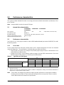
4.5 Formatted capacities
Standard OEM models are formatted to 512 bytes per block. The block size is selectable at format time and
must be a multiple of 4 bytes. Users having the necessary equipment may modify the data block size before
issuing a FORMAT UNIT command and obtain different formatted capacities than those listed.
To provide a stable target capacity environment and at the same time provide users with flexibility if they
choose, Seagate recommends product planning in one of two modes:
Seagate designs specify capacity points at certain block sizes that Seagate guarantees current and future
products will meet. We recommend customers use this capacity in project planning, as it ensures a stable
operating point with backward and forward compatibility from generation to generation. The current guaranteed
operating points for this product are shown below. The Capacity stated is identical when the drive is formatted
with or without PI enabled.
4.6 Programmable drive capacity
Using the MODE SELECT command, the drive can change its capacity to something less than maximum. See
the MODE SELECT (6) parameter list table in the SAS Interface Manual, part number 100293071. A value of
zero in the Number of Blocks field indicates that the drive will not change the capacity it is currently formatted
to have. A number other than zero and less than the maximum number of LBAs in the Number of Blocks field
changes the total drive capacity to the value in the Number of Blocks field. A value greater than the maximum
number of LBAs is rounded down to the maximum capacity.
4.7 Factory-installed options
OEMs may order the following items which are incorporated at the manufacturing facility during production or
packaged before shipping. Some of the options available are (not an exhaustive list of possible options):
• Other capacities can be ordered depending on sparing scheme and LBA size requested.
• Single-unit shipping pack. The drive is normally shipped in bulk packaging to provide maximum protection
against transit damage. Units shipped individually require additional protection as provided by the single unit
shipping pack. Users planning single unit distribution should specify this option.
•The Safety and Regulatory Agency Specifications, part number 75789512, is usually included with each
standard OEM drive shipped, but extra copies may be ordered.
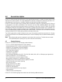
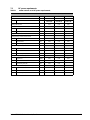
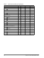
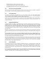
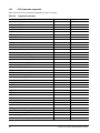
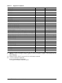
Table 1: Formatted Capacity LBA Count
Capacity (LBAs)
LBA
Size
400GB 200GB 100GB
Decimal Hex Decimal Hex Decimal Hex
512
781,422,768 2E9390B0h 390,721,968 1749F1B0h 195,371,568 BA52230h
520
764,871,800 2D970478h 382,435,904 16CB8240h 191,217,952 B65C120h
524
754,677,072 2CFB7550h 377,338,536 167DBAA8h 188,669,272 B3EDD58h
528
743,833,040 2C55FDD0h 371,916,520 162AFEE8h 185,958,264 B157F78h
4096
97,677,846 5D27216h 48,840,246 2E93E36h 24,421,446 174A446h
4160
96,153,847 5BB30F7h 48,076,924 2DD987Ch 24,038,462 16ECC3Eh
4192
95,419,848 5AFFDC8h 47,709,924 2D7FEE4h 23,854,962 16BFF72h
4224
94,696,970 5A4F60Ah 47,348,485 2D27B05h 23,674,243 1693D83h

Pulsar XT.2 SAS Product Manual, Rev. B 9
4.8 Thin Provisioning
4.8.1 Logical Block Provisioning
The drive is designed with a feature called Thin Provisioning. Thin Provisioning is a technique which does not
require Logical Blocks to be associated to Physical Blocks on the storage medium until such a time as needed.
The use of Thin Provisioning is a major factor in SSD products because it reduces the amount of wear leveling
and garbage collection that must be performed. The result is an increase in the products endurance. For more
details on Logical Block Provisioning and Thin Provisioning, Reference the SBC-3 document provided by the
T-10 committee.
4.8.2 Thin Provisioning capabilities
The level of Thin Provisioning support may vary by product model. Devices that support Thin Provisioning are
allowed to return a default data pattern for read requests made to Logical Blocks that have not been mapped to
Physical Blocks by a previous WRITE command.
In order to determine if Thin Provisioning is supported and what features of it are implemented requires the
system to send a READ CAPACITY 16 (9Eh) command to the drive. Thin Provisioning and the READ
CAPACITY 16 (9Eh) command is defined in the Seagate SCSI Command Reference 100293068.
A logical block provisioning management enabled (LBPME) bit set to one indicates that the logical unit imple-
ments logical block provisioning management. An LBPME bit set to zero indicates that the logical unit is fully
provisioned and does not implement logical block provisioning management.
A logical block provisioning read zeros (LBPRZ) bit set to one indicates that, for an unmapped LBA specified
by a read operation, the device server sends user data with all bits set to zero to the data-in buffer. An LBPRZ
bit set to zero indicates that, for an unmapped LBA specified by a read operation, the device server may send
user data with all bits set to any value to the data-in buffer.
4.8.3 UNMAP
The UNMAP command requests that the device server break the association of a specific Logical Block
address from a Physical Block, thereby freeing up the Physical Block from use and no longer requiring it to
contain user data. An unmapped block will respond to a READ command with data that is determined by the
setting of the LBPRZ bit in the READ CAPACITY parameter data.
4.8.4 FORMAT UNIT command
A device which supports Thin Provisioning will be capable of performing a SCSI FORMAT UNIT command
which allocates Logical Blocks Addresses that are not linked to Physical Block Locations. A FORMAT com-
mand will cause all LBAs to become unmapped.
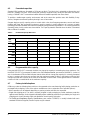
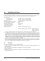
4.8.5 Protection Information (PI) and Security (SED)
The requirements in this section apply to any device which supports LBA unmapping.
In SCSI devices, umapped LBAs are defined as part of the Thin Provisioning model. Support of the Thin Provi-
sioning model is indicated by the LBPME bit having a value of '1' in the READ CAPACITY (16) parameter data.
Table 2: Thin Provisioning Product Configuration
Product Configuration LBPME LBPRZ
Non-SED Supported Supported
SED Supported Not Supported

10 Pulsar XT.2 SAS Product Manual, Rev. B
When a region of LBA's are erased via cryptographic erase, as part of the erase, the drive shall unmap those
LBAs.
If the host attempts to access an unmapped or trimmed LBA, the drive shall return scrambled data. For a given
LBA, the data shall be identical from access to access, until that LBA is either updated with actual data from
the host or that LBA is cryptographically erased. The drive shall report a value of '0' in the LBPRZ field returned
in the READ CAPACITY (16) parameter data.
If the host attempts to access an unmapped LBA on a drive that has been formatted with Protection Informa-
tion (PI), the drive shall return scrambled PI data for that LBA. Depending on the value of the RDPROTECT
field in the data-access command CDB, this may result in the drive returning a standard PI error to the host.
If the host reduces the addressable capacity of the drive via a MODE SELECT command, the drive shall
unmap or trim any LBA within the inaccessible region of the device.
Additionally, an UNMAP command is not permitted on a locked band.
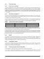
Table 3: PI and SED Drive Configuration
Drive Configuration
Standard SED
PI Setting Disabled Enabled Disabled Enabled
PROT_EN bit 010 1
LBPME bit 111 1
LBPRZ bit 110 0
PI Check Requested N/A Yes No N/A Yes No
DATA Returned for
Thin Provisioned LBA
0x00 0x00 0x00 Random None Random
PI Returned for
Thin Provisioned LBA
None 0xFF 0xFF None None
Scrambled
PI data
PI Check Performed N/A NoNoN/A YesNo
Error reported to Host No No No No Yes No

Pulsar XT.2 SAS Product Manual, Rev. B 11
5.0 Performance characteristics
This section provides detailed information concerning performance-related characteristics and features of Pul-
sar XT.2 drives.
Note. Data provided is based on format at 512-bytes.
5.1 Internal drive characteristics
ST400FX0002 ST200FX0002 ST100FX0002
ST400FX0012
Drive capacity 400 200 100 GB (formatted, rounded off value)
Flash Memory Type NAND SLC
Emulated LBA Size 512, 520, 524, 528, 4096, 4160, 4192, or 4224
Native Programmable Page Size 4096 User Bytes
Default Transfer Alignment Offset 0
5.2 Performance characteristics
See Section 11.4.1, "SAS physical interface" and the SAS Interface Manual (part number 100293071) for addi-
tional timing details.
5.2.1 Access time
Access measurements are taken with nominal power at 25°C ambient temperature. All times are measured
using drive diagnostics. The specifications in the table below are defined as follows:
• Page-to-page access time is an average of all possible page-to-page accesses in both directions for a
sequentially preconditioned drive.
• Average access time is a true statistical random average of at least 5000 measurements of accesses
between programmable pages on a randomly preconditioned drive.
Table 4: Typical Access Time (µsec)
400GB
1,2
1. Execution time measured from receipt of the Command to the Response.
2. Assumes no errors.
3. Typical access times are measured under nominal conditions of temperature, voltage, and horizontal orientation as
measured on a representative sample of drives.
Note. These drives are designed to provide the highest possible performance under typical conditions.
However, due to the nature of Flash memory technologies there are many factors that can result in
values different than those stated in this specification
2.
100/200 GB
1,2
Read Write Read Write
Average
Typical
3
268 133 208 121
Page to Page 268 133 207 121
Average Latency 247 188

12 Pulsar XT.2 SAS Product Manual, Rev. B
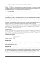
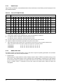
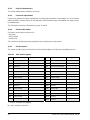
5.2.2 FORMAT UNIT command execution time for 512-byte LBA’s (minutes)
The device may be formatted as either a Thin Provisioned
device or a Fully Provisioned device. The default
format is Thin Provisioned and is recommended for most applications. Thin Provisioning provides the most
flexibility for the device to manage the flash medium to maximize endurance.
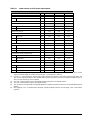
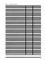
Table 5:
Maximum FORMAT UNIT Times (minutes)
Configuration
Format Mode DCRT Bit IP Bit 400GB 200GB 100GB
Non-SED
(Default) Thin Provisioned DCRT = 0 IP = 0 5 5 5
Non-SED
(Default) Thin Provisioned DCRT = 1 IP = 0 5 5 5
Non-SED
Fully Provisioned DCRT = 0 IP = 1 140 60 30
Non-SED
Fully Provisioned DCRT = 1 IP = 1 100 40 20
SED
(Default) Thin Provisioned DCRT = 0 IP = 0 5 N/A N/A
SED
(Default) Thin Provisioned DCRT = 1 IP = 0 5 N/A N/A
SED
Fully Provisioned DCRT = 0 IP = 1 140 N/A N/A
SED
Fully Provisioned DCRT = 1 IP = 1 100 N/A N/A
5.2.3 Performance
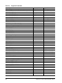
Table 6: Performance
Notes 400GB 200GB 100GB
Maximum Burst Transfer Rate 600MB/s
Peak sequential 128KB read/write data transfer rate (MB/s max) [1] 360/300
Sustained sequential 128KB read/write dat
a transfer rate (MB/s) [1] 300/300 300/200 300/100
Peak 4KB random read/write command rate (IOPs) [2] 48,000/22,000
Sustained 4KB random read/write command rate (IOPs) [2] 48,000/
22
,000
48,000/
16,000
48,000/
8000
Sustainable 4KB Random combined IOPS for 5 year Endurance
(65%/35% R/W, 70% Duty Cycle)
[3] 31,000 31,000 31,000
[1] Testing performed at Queue Depth = 32, Sequentiall
y Preconditioned drive, using IOMeter 2006.7.27.
[2] Testing performed at Queue Depth = 32, Randomly
Preconditioned drive, using IOMeter 2006.7.27.
[3] Testing performed at Queue Depth = 32, Non-Preconditioned drive, using IOMeter 2006.7.27.
Note. IOMeter is available at http://www.iometer.org/ or http://sourceforge.net/projects/iometer/.
IOMeter is licensed under the Intel Open Source Licen
se and the GNU General Public License. Intel
does not endorse any IOMeter results.
Peak performance is defined as the typical best case performance
that the product will be able to
achieve when the product is preconditioned as mentioned and host commands are aligned on 4KB
boundaries.
Sustained performance is defined as the typical worst case
performance that the product will be able to
achieve when the product is preconditioned as mentioned and host commands are aligned on 4KB boundar-
ies. Write values also take into account the worst case performance throttling that may occur to ensure the
product meets specified reliability specifications.
Page is loading ...
Page is loading ...
Page is loading ...
Page is loading ...
Page is loading ...
Page is loading ...
Page is loading ...
Page is loading ...
Page is loading ...
Page is loading ...
Page is loading ...
Page is loading ...
Page is loading ...
Page is loading ...
Page is loading ...
Page is loading ...
Page is loading ...
Page is loading ...
Page is loading ...
Page is loading ...
Page is loading ...
Page is loading ...
Page is loading ...
Page is loading ...
Page is loading ...
Page is loading ...
Page is loading ...
Page is loading ...
Page is loading ...
Page is loading ...
Page is loading ...
Page is loading ...
Page is loading ...
Page is loading ...
Page is loading ...
Page is loading ...
Page is loading ...
Page is loading ...
Page is loading ...
Page is loading ...
Page is loading ...
Page is loading ...
Page is loading ...
Page is loading ...
Page is loading ...
Page is loading ...
Page is loading ...
Page is loading ...
Page is loading ...
Page is loading ...
Page is loading ...
Page is loading ...
Page is loading ...
Page is loading ...
-
 1
1
-
 2
2
-
 3
3
-
 4
4
-
 5
5
-
 6
6
-
 7
7
-
 8
8
-
 9
9
-
 10
10
-
 11
11
-
 12
12
-
 13
13
-
 14
14
-
 15
15
-
 16
16
-
 17
17
-
 18
18
-
 19
19
-
 20
20
-
 21
21
-
 22
22
-
 23
23
-
 24
24
-
 25
25
-
 26
26
-
 27
27
-
 28
28
-
 29
29
-
 30
30
-
 31
31
-
 32
32
-
 33
33
-
 34
34
-
 35
35
-
 36
36
-
 37
37
-
 38
38
-
 39
39
-
 40
40
-
 41
41
-
 42
42
-
 43
43
-
 44
44
-
 45
45
-
 46
46
-
 47
47
-
 48
48
-
 49
49
-
 50
50
-
 51
51
-
 52
52
-
 53
53
-
 54
54
-
 55
55
-
 56
56
-
 57
57
-
 58
58
-
 59
59
-
 60
60
-
 61
61
-
 62
62
-
 63
63
-
 64
64
-
 65
65
-
 66
66
-
 67
67
-
 68
68
-
 69
69
-
 70
70
-
 71
71
-
 72
72
-
 73
73
-
 74
74


Ask a question and I''ll find the answer in the document
Finding information in a document is now easier with AI
Related papers
-
Seagate ST800FM0023 User manual
-
Seagate ST800FM0043 User manual
-
-
-
-
-
Seagate ST6000NM0074 User manual
-
-
Seagate ST1920FM0003 Nytro 1200.2 SSD 1920GB SAS Drive User manual
-
Seagate ST2000NX0343 Exos 7E2000 12 Gb/s SAS 512E 2 TB Hard Drive User manual
Other documents
-
Toshiba storage.toshiba.eu MK1060GSC User manual
-
Eaton 66027 Datasheet
-
C2G 0.5m SAS 32-pin -> 4 ESATA Cable Datasheet
-
Quantum DLT-S4 Reference guide
-
-
-
Intel SSDSC1NA200G3 Datasheet
-
Bowens Pulsar User manual
-
3M Serial Attached SCSI (SAS) Connector, SBR-RA-29-S-ML, SBR Series Important information
-