Page is loading ...

INSTALLATION INSTRUCTIONS
CREATING POSITIVE CUSTOMER EXPERIENCES
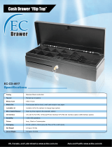
GB-AVSTOR5
Ceiling Equipment Storage Box with Pipe Coupler
9534-500-021-00

Page 2 Visit the Premier Mounts website at www.mounts.com Installation Instructions
Contents
Contact Premier Mounts with any questions:
(800) 368-9700
GB-AVSTOR5
Warning Statements
Weight Limit
Maximum Weight:
THE CEILING STRUCTURE MUST BE CAPABLE OF
SUPPORTING AT LEAST FIVE TIMES THE WEIGHT OF
THE CEILING BOX. IF NOT, THE CEILING STRUCTURE
MUST BE REINFORCED.
PRIOR TO THE INSTALLATION OF THIS PRODUCT, THE INSTALLATION INSTRUCTIONS MUST BE READ AND
COMPLETELY UNDERSTOOD. KEEP THESE INSTALLATION INSTRUCTIONS IN AN EASILY ACCESSIBLE LOCATION
FOR FUTURE REFERENCE.
PROPER INSTALLATION PROCEDURE BY A QUALIFIED SERVICE TECHNICIAN MUST BE FOLLOWED, AS OUTLINED
IN THESE INSTALLATION INSTRUCTIONS. FAILURE TO DO SO COULD RESULT IN PROPERTY DAMAGE, SERIOUS
PERSONAL INJURY, OR EVEN DEATH.
SAFETY MEASURES MUST BE PRACTICED AT ALL TIMES DURING THE ASSEMBLY OF THIS PRODUCT. USE
PROPER SAFETY EQUIPMENT AND TOOLS FOR THE ASSEMBLY PROCEDURE TO PREVENT PERSONAL INJURY.
PREMIER MOUNTS DOES NOT WARRANT AGAINST DAMAGE CAUSED BY THE USE OF ANY PREMIER MOUNTS
PRODUCT FOR PURPOSES OTHER THAN THOSE FOR WHICH IT WAS DESIGNED OR DAMAGE CAUSED BY
UNAUTHORIZED ATTACHMENTS OR MODIFICATIONS, AND IS NOT RESPONSIBLE FOR ANY DAMAGES, CLAIMS,
DEMANDS, SUITS, ACTIONS OR CAUSES OF ACTION OF WHATEVER KIND RESULTING FROM, ARISING OUT OF OR
IN ANY MANNER RELATING TO ANY SUCH USE, ATTACHMENTS OR MODIFICATIONS.
Atleasttwoqualiedpeopleshouldperformtheassemblyprocedure.Personalinjuryand/orpropertydamagecanresult
fromdroppingormishandlingtheprojector.
Thisproductisintendedforindooruseonly.Useofthisproductoutdoorscouldleadtoproductfailureand/orserious
personalinjury.
Donotinstallnearsourcesofhighheat.Donotinstallonastructurethatispronetovibration,movementorchanceof
impact.
Weight Limit. .................................................................................................................................................................... 2
Warning Statements. ....................................................................................................................................................... 2
Installation Tools. ............................................................................................................................................................. 3
Parts List.......................................................................................................................................................................... 3
Features. ......................................................................................................................................................................... 4
GB-AVSTOR5 Installation. .............................................................................................................................................. 5
Introduction. .............................................................................................................................................................. 5
LidRemoval.............................................................................................................................................................. 5
Ceiling Box Installation. ................................................................................................................................................... 6
Wiring the Electrical Box................................................................................................................................................ 10
RemovingtheElectricalKnockouts(optional). ....................................................................................................... 10
Mounting Tray Installation...............................................................................................................................................11
CeilingNPTAdapterPlateAdjustment. ......................................................................................................................... 12
Securingthe1½˝NPTPipetotheGB-AVSTOR5. ....................................................................................................... 12
SecuringtheLid............................................................................................................................................................. 13
TechnicalSpecications. ............................................................................................................................................... 14
Warranty. ....................................................................................................................................................................... 15
50 lbs.

Installation Instructions Visit the Premier Mounts website at www.mounts.com Page 3
GB-AVSTOR5
Parts List
Installation Tools
Thefollowingtoolsmayberequireddependinguponyourparticularinstallation.Theyarenotincluded.
MakesureyourPremierMountsproducthasthefollowinghardwareandcomponentsbeforebeginninginstallation.If
therearepartsmissingand/ordamaged,stoptheinstallationandcallPremierMountsat(800)368-9700.
GB-AVSTOR5 Ceiling Box (Qty 1)
GB-AVSTOR5 Hardware
M5x8mmPhillipsHeadScrews
(Qty 6)
Pencil ProtectiveEyewear
PhillipsTipScrewdriverHandHeldDrill
Ladder
QuickLocks
(Qty 4)
1
/16˝BraidedCable
(Qty4Strands)
Quick Lock Cable Kit
¼” x 3” Eye Lag Screws
(Qty 4)
M6 x 2.4” Eye Anchor Bolts
(Qty 4)
Keys (Qty 2)
1/8˝DrillBit ¼˝ConcreteDrillBit
Hammer
Flat Washers
ZipTies(Qty12)
EquipmentMountingTray(Qty1)
M5 x 6mm Set
Screw (Qty 1)

Page 4 Visit the Premier Mounts website at www.mounts.com Installation Instructions
GB-AVSTOR5
Features
Removable Equipment Tray
TrayallowsA/Vcomponents
tobepre-wiredpriortothe
installation
Security
Lockableaccesspanelkeeps
A/Vgearsafe
Top Knockouts
Multiple,singleanddual-gangknockoutsfor
signalandpower(knockoutcoversnotshown)
Tile Replacement
Replacesstandard2’x2’
ceiling tile
Includes the Quick Lock Cable Kit
Top View
Side Knockouts
Multiple1”and3/4”knockouts
provideelectricalconduit
connector access
TheGB-AVSTOR5CeilingEquipmentStorageGearBox™withintegratedpipecouplerprovidesasecureanddiscrete
storage-and-mountingsolutionforfalseceilingprojectorinstallations.Integratedpowerreceptacles,aremovable
equipmentmountingtrayandanadjustablemountingplatformfor1½”NPTpipemaketheGB-AVSTOR5an
indispensible,centralizedA/Vinstallationaccessory.
Mounting Coupler
1½”NPTpipecoupler
provides6”oflateralshift
Power Receptacle
Convenientlyconnectthe
projectororanotherdeviceto
theintegratedelectricaloutlet
Power Toggle
Easilyturnonoroff
thepowerreceptacle

Installation Instructions Visit the Premier Mounts website at www.mounts.com Page 5
GB-AVSTOR5
PleasereadtheseinstallationinstructionsthoroughlybeforeinstallingyourPremierMountsproduct.
Pleasetakeaminutetofamiliarizeyourselfwiththecontentsofthepackageandmakesureyouhaveallthepartsand
toolsyouneedtosafelycompletetheinstallation.
Inaddition,somestepsofthisinstallationmayrequiretwopeopletopreventpersonalinjuryand/ordamagetoyour
equipment.Pleaseobserveallwarningsinthefollowinginstallationprocedureandutilizepropersafetyequipmentat
all times.
GB-AVSTOR5 Installation
Introduction
➊
Unlockandopenthelid.
➋
Pushthelidinandawayfromthemetalhinges
(Figure 1).
➌
Pushthelidinthedirectionofthemountingcoupler
(Figure 2).
➍
Oncethelidhingeisunattached,pullthelidcarefully
outfromtheceilingbox.
Go to Ceiling Box Installationonpage6.
Figure 1
Figure 2
CeilingBoxSideView
Lid Removal

Page 6 Visit the Premier Mounts website at www.mounts.com Installation Instructions
Ceiling Attachment
Solid Surface
Wood Stud
➊
Determine the mounting location.
➋
Usea1/8”drillbittopre-drillthemountingholes.
➌
Securethefour(4)¼”eyelagscrewstothewood
studintheceiling.
➍
Runtheopenendofthe
1
/16˝braidedcablethrough
the hole in an eye lag screw.
➎
Runtheopenendthroughtheloop.
➏
Pulltheopenenddownuntilthe
1
/16˝braidedcable
tightensaroundtheeyelagscrew.
➐
Repeatsteps4-6fortheremainingthreemounting
points.
The ceiling box must be secured using the Quick
Locksand
1
/16˝braidedcables(supplied).
➊
Determine the mounting location.
➋
Usea¼”concretedrillbittodrillthemountingholes.
➌
Placetheconcreteeyeanchorboltsintothepre-
drilledholesandgentlytapintoplaceusingarubber
mallet or hammer.
➍
Runtheopenend
1
/16˝braidedcablethrough the hole
in an eye anchor bolt.
➎
Runtheopenendthroughtheloop.
➏
Pulltheopenenddownuntilthebraidedcable
tightensaroundtheeyeanchorbolt.
➐
Repeatsteps4-6fortheremainingthreemounting
points.
Wood Stud Ceiling
Concrete Ceiling
Eye Lag Screw
Eye Anchor Bolt
GB-AVSTOR5
➊
Determinethedesiredlocationwherethe
GB-AVSTOR5istobelocated.
➋
Removetheceilingtilewheretheceilingboxwillbe
mounted.
Storetheceilingtileinasafelocationintheevent
thatitneedstobereused.
Ceiling Tile
Ceiling Box Installation

Installation Instructions Visit the Premier Mounts website at www.mounts.com Page 7
GB-AVSTOR5
Ceiling Truss
➊
Loopthebraidedcablearoundthetruss.
➋
Runtheopenend
1
/16˝braidedcablethrough the
loop.
➌
Pulltheopenenddownuntilthe
1
/16˝braidedcable
tightensaroundthetruss.
➍
Repeatsteps1-3fortheremainingthreemounting
points.
Go to Quick Lock Operationonpage8.
Truss Ceiling
GB-AVSTOR5

Page 8 Visit the Premier Mounts website at www.mounts.com Installation Instructions
Quick Lock Operation
1
/16˝BraidedCable
Mounting Hole
Please follow the steps below in numerical order , ,
and tocorrectlyinstalltheQuickLockCableKit.
Toreleaseorrelievetensiononthe
1
/16˝braided
cable,slidethereleasepintodisengage.
CableOutput
CableInput
Release Pin
Release Pin
1
/16˝BraidedCable
Mounting Hole
Release Pin
Step 1
GB-AVSTOR5

Installation Instructions Visit the Premier Mounts website at www.mounts.com Page 9
GB-AVSTOR5
W
Ceiling
Framework
QuickLock
➋
Adjustthe
1
/16˝braidedcablesothatthecableformsa
15°angleawayfromthecorneroftheceilingbox.
Whenadjustingthetensionoftheweight-bearing
sideoftheQuickLock,the
1
/16˝braidedcable must
bepulledthroughtheQuickLockuntilthedesired
tensionisattained.Donotovertighten.
➌
Whenyouhavethedesiredtension,pullthe
1
/16˝
braidedcablethroughtheothersideoftheQuick
Lock.
Oncethetensionhasbeenadjusted,besurethat
thereisaminimumof6”ofexcess
1
/16˝braidedcable
onthenon-weightbearingsideoftheQuickLock.
➍
Usecablecutterstoremoveanyremaining
1
/16˝
braidedcable(optional).
Go to Wiring the Electrical Boxonpage10.
6” Excess
1
/16˝BraidedCable
1
/16˝Braided
Cable To Ceiling
Attachment
Step 2
Itisrecommendedthatthefollowingstepsbe
performedbytwopeople.
➊
Lowertheceilingboxintotheexposedceiling
framework.
Makesuretheceilingboxisseatedcompletelyin
theceilingframeworkbeforereleasingit.
15°

GB-AVSTOR5
Page 10 Visit the Premier Mounts website at www.mounts.com Installation Instructions
➊
Removescrewsfromaroundthedesiredelectrical
knockouts(Figure1)todetachtheircovers.
➋
Removetheknockoutcoversfromthetopofthe
GB-AVSTOR5 (Figure 2).
Go to Mounting Tray Installationonpage11.
1-and2-gangelectricalknockouts
insidetheGB-AVSTOR5
Figure 1
Figure 2
Detachtheknockout
cover
Ifyounolongerwanttouseaknockout,re-attach
itscovertopreventexcessiveairowintothe
ceiling.
WARNING!
Donotinstallormodifyelectricalwiringunlessyou
areacertiedelectrician.
➊
Removetwo(2)M4x8mmPhillipscomboscrewsto
detachtheelectricalboxfromtheceilingbox
(Figure 1).
➋
Haveacertiedelectriciandothefollowing:
•
Punchouttheappropriatepowerknockout(s)onthe
sideoftheceilingbox(Figure2).
•
Hookupallloosewiringintheelectricalbox.
•
Re-installtheelectricalboxinsidetheceilingbox.
Continue to Removing the Electrical Knockouts
(optional) below.
M4x8mmPhillips
combo screw
Removing the Electrical Knockouts (optional)
Wiring the Electrical Box
Figure 1
Figure 2
PowerKnockouts
Electricalboxinsidethe
ceiling box shown

GB-AVSTOR5
Installation Instructions Visit the Premier Mounts website at www.mounts.com Page 11
➊
Insertfour(4)M5x8mmPhillipsheadscrewsloosely
intotheouterholesinsidetheGB-AVSTOR5(Figure
1).
➋
Placethemountingtrayintothemiddlesectionofthe
GB-AVSTOR5 (Figure 2).
➌
HookthemountingtrayontotheheadsoftheM5
x8mmPhillipsheadscrewsontheGB-AVSTOR5
(Figure 3).
➍
Inserttwo(2)M5x8mmPhillipsheadscrewsintothe
middlemountingholesofthemountingtray.
➎
UseaPhillipstipscrewdrivertotightenallsix(6)
screws.
Continue to Ceiling NPT Adapter Plate Adjustment on
page12.
Donotovertightenthemountingscrews.
Attaching the Mounting Tray to the GB-AVSTOR5
ZipTie
➊
Placeyourelectroniccomponentsontothemounting
tray.
➋
Aligntheelectroniccomponentssothattheweightis
distributedasevenlyaspossible.
➌
Runtheziptiesthroughthemountingslotsonthe
tray,underneaththemountingtrayandupthrough
themountingslotontheothersideoftheelectronic
component.
➍
Tightentheziptiedownandcutoffanyexcesszip
tie.
Mounting Tray
Asareminder,smallscrewsandatwashersmay
alsobeusedandarestronglyrecommended.
Attaching Equipment to the Tray
Mounting Tray Installation
Foreaseofinstallation,themountingtraycomespackagedinaseparateboxwithinthemastercarton.
Installersmaypre-wirethemountingtraypriortotheGB-AVSTOR5ceilingboxinstallation.Zipties(included),
smallscrewsandatwashersarestronglyrecommendedtoholdallequipmentinplace.
Figure 1
Figure 2 Figure 3
M5x8mmPhillips
headscrew
InsideviewofGB-AVSTOR5

GB-AVSTOR5
Page 12 Visit the Premier Mounts website at www.mounts.com Installation Instructions
➊
Locatethepre-installedceilingNPTadapterplate
insidetheGB-AVSTOR5.
➋
Loosen the wingnuts.
➌
SlidetheceilingNPTadapterplatetothedesired
position.
➍
Re-tighten the wingnuts.
Continue to Securing the 1 ½˝ NPT Pipe to the GB-
AVSTOR5 below.
Ceiling NPT Adapter Plate Adjustment
ViewoftheceilingNPT
adapterplateinsidethe
GB-AVSTOR5
➊
Securethe1½″NPTpipetothemountingcoupler
andtightenthepipe.
➋
Useone(1)M5x6mmsetscrewtosecurethepipe
totheplate.
TheM5x6mmsetscrewmustbeusedto
stabilizethe1½″NPTpipe.
Go to Securing the Lidonpage13.
Securing the 1 ½˝ NPT Pipe to the GB-AVSTOR5
1½″NPTpipe
SideviewoftheceilingNPT
adapterplateinsidethe
GB-AVSTOR5
M5 x 6mm set screw

Installation Instructions Visit the Premier Mounts website at www.mounts.com Page 13
Step 1
➊
Re-attachtheceilingboxlidtotheceilingbox.
➋
Swingtheceilingboxlidupintoplace.
Securing the Lid
Step 2
➊
Holdthelidinplace.
➋
Useakey(supplied)tolockthelidinplace.
➌
Donotreleasetheceilingboxliduntilyouaresure
thatthelockhasbeenengagedandthelidissecure.

Page 14 Visit the Premier Mounts website at www.mounts.com Installation Instructions
Technical Specications
All measurements are in inches [mm].
6.000
152.40
23.875
606.43
21.500
546.10
5.05
128.21
21.500
546.10
22.390
568.71
5.000
127
23.875
606.43
21.348
5.048
128.21
18.859
479.01

Installation Instructions Visit the Premier Mounts website at www.mounts.com Page 15
PREMIER MOUNTS
LIMITED LIFETIME WARRANTY
What and Who is Covered by this Limited Warranty and for How Long
PremierMountswarrantsthisproducttobefreefromdefectsinmaterialandworkmanshipforthelifetimeoftheoriginal
ownerofthisproduct.Thelimitedwarrantyisvalidonlyfortheoriginalpurchaseroftheproduct.
What Premier Mounts Will Do
AtthesoleoptionofPremierMounts,PremierMountswillrepairorreplaceanyproductorproductpartthatisdefective.
IfPremierMountschoosestoreplaceadefectiveproductorpart,areplacementproductorpartwillbeshippedtoyou
atnocharge,butyoumustpayanylaborcosts.
What is Not Covered; Limitations
PREMIER MOUNTS DISCLAIMS ANY LIABILITY FOR DAMAGE TO MOUNTS, ADAPTERS, DISPLAYS,
PROJECTORS, OTHER PROPERTY, OR PERSONAL INJURY RESULTING, IN WHOLE OR IN PART, FROM
IMPROPER INSTALLATION, MODIFICATION, USE OR MISUSE OF ITS PRODUCTS.
PREMIER MOUNTS DISCLAIMS ALL OTHER WARRANTIES, EXPRESS OR IMPLIED, INCLUDING WARRANTIES
OF MERCHANTABILITY AND FITNESS FOR A PARTICULAR PURPOSE. PREMIER MOUNTS IS NOT
RESPONSIBLE FOR INCIDENTAL OR CONSEQUENTIAL DAMAGES, INCLUDING BUT NOT LIMITED TO,
INABILITY TO USE ITS PRODUCTS OR LABOR COSTS FOR REMOVING AND REPLACING DEFECTIVE
PRODUCTS OR PARTS. SOME STATES DO NOT ALLOW THE EXCLUSION OR LIMITATION OF INCIDENTAL OR
CONSEQUENTIAL DAMAGES, SO THE ABOVE LIMITATION OR EXCLUSION MAY NOT APPLY TO YOU.
What Customers Must Do for Limited Warranty Service
IfyoudiscoveraproblemthatyouthinkmaybecoveredbythewarrantyyouMUSTREPORTitinwritingtotheaddress
belowwithinthirty(30)days.Proofofpurchase(anoriginalsalesreceipt)fromtheoriginalconsumerpurchasermust
accompanyallwarrantyclaims.Warrantyclaimsmustalsoincludeadescriptionoftheproblem,thepurchaser’sname,
address,andtelephonenumber.GeneralinquiriescanbeaddressedtoPremierMountsCustomerServiceat1-800-
368-9700.Warrantyclaimswillnotbeacceptedoverthephoneorbyfax.
Premier Mounts
Attn: Warranty Claim
3130EastMiralomaAve.
Anaheim, CA 92806
How State Law Applies
THIS WARRANTY GIVES YOU SPECIFIC LEGAL RIGHTS, AND YOU MAY ALSO HAVE OTHER RIGHTS WHICH
VARY FROM STATE TO STATE.
©Premier Mounts 2011
Warranty
Disclaimer
PremierMountsintendstomakethismanualaccurateandcomplete.However,PremierMountsmakesnoclaimthat
theinformationcontainedhereincoversalldetails,conditionsorvariations,nordoesitprovideforeverypossible
contingencyinconnectionwiththeinstallationoruseofthisproduct.Theinformationcontainedinthisdocument
issubjecttochangewithoutnoticeorobligationofanykind.PremierMountsmakesnorepresentationofwarranty,
expressedorimplied,regardingtheinformationcontainedherein.PremierMountsassumesnoresponsibilityfor
accuracy,completenessorsufciencyoftheinformationcontainedinthisdocument.
NORTH AMERICA
3130EastMiralomaAvenue
Anaheim, CA 92806 USA
USAandCanada
Phone: 1-800-368-9700
Fax: 1-800-832-4888
Other Locations
Phone: (001) 714-632-7100
Fax: (001) 714-632-1044
EUROPE
Unit3,TheMooringsBusinessPark,
ChannelWay,Longford,
Coventry,CV66RH,UK
Phone: +44 (0) 24 7664 4105
Fax: +44 (0) 24 7664 4165
Contact Us
Warranty
/