Gigabyte GA-6LISL User manual
- Category
- Server/workstation motherboards
- Type
- User manual

GA-6LISL
LGA1150 socket motherboard for Intel
®
E3 series processors
User's Manual
Rev. 1101

Copyright
© 2014 GIGA-BYTE TECHNOLOGY CO., LTD. All rights reserved.
The trademarks mentioned in this manual are legally registered to their respective owners.
Disclaimer
Information in this manual is protected by copyright laws and is the property of GIGABYTE.
Changes to the specifications and features in this manual may be made by GIGABYTE
without prior notice. No part of this manual may be reproduced, copied, translated, transmitted, or
published in any form or by any means without GIGABYTE's prior written permission.
Documentation Classications
In order to assist in the use of this product, GIGABYTE provides the following types of documentations:
For detailed product information, carefully read the User's Manual.
For product-related information, check on our website at:
http://www.gigabyte.com

- 3 -
Table of Contents
Box Contents ...................................................................................................................5
GA-6LISL Motherboard Layout ........................................................................................ 6
GA-6LISL Block Diagram.................................................................................................8
Chapter 1 Hardware Installation .....................................................................................9
1-1 Installation Precautions .................................................................................... 9
1-2 ProductSpecications .................................................................................... 10
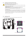
1-3 Installing the CPU and CPU Cooler ............................................................... 12
1-3-1 Installing the CPU ...................................................................................................12
1-3-2 Installing the CPU Cooler .......................................................................................14
1-4 Installing the Memory ..................................................................................... 15
1-4-1 DualChannelMemoryConguration .....................................................................15
1-4-2 Installing a Memory ...............................................................................................16
1-5 Back Panel Connectors .................................................................................. 17
1-6 Internal Connectors ........................................................................................ 19
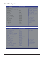
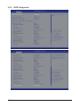
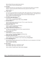
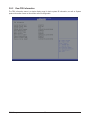
Chapter 2 BIOS Setup ..................................................................................................31
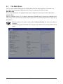
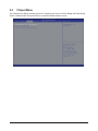
2-1 The Main Menu .............................................................................................. 33
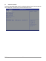
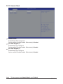
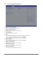
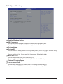
2-2 Advanced Menu ............................................................................................. 35
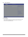
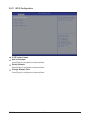
2-2-1 ACPIConguration .................................................................................................36
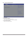
2-2-2 Trusted Computing (Optional) ................................................................................37
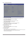
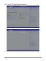
2-2-3 PCI Subsystem Settings .........................................................................................38
2-2-3-1 PCI Express Settings ..............................................................................................40
2-2-4 CPUConguration ..................................................................................................42
2-2-5 SATAConguration.................................................................................................47
2-2-5-1 SoftwareFeatureMaskConguration ....................................................................49
2-2-6 InfoReportConguration .......................................................................................51
2-2-7 USBConguration ..................................................................................................52
2-2-8 SuperIOConguration ...........................................................................................53
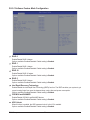
2-2-9 Serial Port Console Redirection .............................................................................55
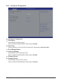
2-2-10 Network Stack ........................................................................................................58
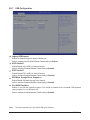
2-2-11 iSCSIConguration ................................................................................................59
2-2-12 Intel (R) I210 Gigabit Network Connection .............................................................60
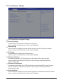
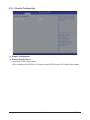
2-3 Chipset Menu ................................................................................................. 62
2-3-1 SystemAgent(SA)Conguration ............................................................................63
2-3-1-1 GraphicConguration .............................................................................................64
2-3-1-2 NBPCIeConguration ...........................................................................................65
2-3-1-3 MemoryConguration ............................................................................................67

- 4 -
2-3-2 PCH-IOConguration .............................................................................................69
2-3-2-1 PCIExpressConguration .....................................................................................71
2-3-2-2 USBConguration ..................................................................................................72
2-3-3 Intel Server Platform Services ................................................................................73
2-4 Security Menu ................................................................................................ 74
2-4-1 Secure Boot menu .................................................................................................75
2-4-1-1 Image Execution Policy
........................................................................................76
2-4-1-2 Key Management
.................................................................................................77
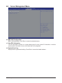
2-5 Server Management Menu ............................................................................. 79
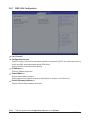
2-5-1 BMCLANConguration .........................................................................................80
2-5-2 View FRU Information ...........................................................................................81
2-5-3 System Event Log ..................................................................................................82
2-6 Event Logs Menu ........................................................................................... 83
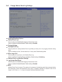
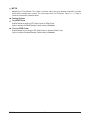
2-6-1 Change Smbios Event Log Settings .......................................................................84
2-6-2 View Smbios Event Log ..........................................................................................86
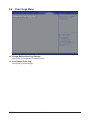
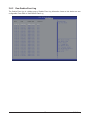
2-7 Boot Menu ...................................................................................................... 87
2-7-1 CSM16 Parameters ...............................................................................................89
2-7-2 CSM Parameters ...................................................................................................90
2-8 Exit Menu ....................................................................................................... 92
2-9 BIOS Beep Codes .......................................................................................... 93
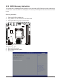
2-10 BIOS Recovery Instruction ............................................................................. 94
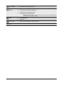
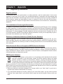
Chapter 3 Appendix ......................................................................................................95
3-1 Regulatory Statements ................................................................................... 95

- 5 -
Box Contents
GA-6LISL motherboard
Driver CD
Two SATA cables
I/O Shield
• The box contents above are for reference only and the actual items shall depend on the product package you obtain.
The box contents are subject to change without notice.
• The motherboard image is for reference only.

- 6 -
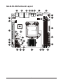
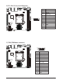
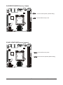
GA-6LISL Motherboard Layout
3
421 5 6
7
8
9
10
11
12
13
14
15
17
1819202122
24
25
23
2627
28
29
30
36
37
38
35
32
33
34
31
16

- 7 -
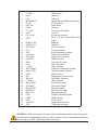
Item Code Description
1 R_USB1 USB 2.0 ports
2 LAN2 LAN2 port
3 LAN1 LAN1 port
4 NMI_BMCRST Reset button (top)/NMI button (bottom)
5 ID_SW ID Switch button
6 PWR_SW Power button
7 COM1 Serial port
8 FP_VGA1 Front panel VGA header
9 VGA1 VGA port
10 P12V_AUX1 4 pin power connector
11 CFG5
PCI-E x16 and x8 bandwidth switch
jumper
12 DDR3_P0_B0 DIMM slot
13 DDR3_P0_A0 DIMM slot
14 CPU0_FAN CPU fan connector
15 FP_1 Front panel header
16 ATX1 24 pin main power connector
17 SYS_FAN2 System fan connector#2
18 SYS_FAN3 System fan connector#3
19 PWR_DET PMBus connector
20 CPU0 Intel LGA1150 socket
21 U516 Intel C226 chipset
22 F_USB3 USB 3.0 header
23 SATA_DOM4 SATA port 4 DOM support jumper
24 CASE_OPEN Case open intrusion header
25 HDMI HDMI connector
26 BAT Battery power cable connector
27 SATA0~4 SATA 6Gb/s connectors
28 F_USB2_1 USB 2.0 header
29 SATA_SGPIO SATA SGPIO header
30 CLRCMOS Clear CMOS jumper
31 ME_UPDATE ME Update jumper
32 BIOSRCVR BIOS recovery jumper
33 BMC_LED1 BMC readiness LED
34 U546 ASPEED 2300 BMC chipset
35 IPMB1 IPMB connector
36 PCIE_1 PCI-E x16 slot
37 SYS_FAN1 System fan connector#1
38 TPM TPM module connector
CAUTION! If a SATA type hard drive is connected to the motherboard, please ensure the jumper is
closed and set to 2-3 pins (Default setting), in order to reduce any risk of hard disk damage. Please
refer to Page 30 for SATA_DOM4 jumper setting instruction.

- 8 -
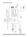
GA-6LISL Block Diagram

- 9 - Hardware Installation
1-1 Installation Precautions
The motherboard contains numerous delicate electronic circuits and components which can
become damaged as a result of electrostatic discharge (ESD). Prior to installation, carefully read
the user's manual and follow these procedures:
• Prior to installation, do not remove or break motherboard S/N (Serial Number) sticker or
warranty sticker provided by your dealer. These stickers are required for warranty validation.
• Always remove the AC power by unplugging the power cord from the power outlet before
installing or removing the motherboard or other hardware components.
• When connecting hardware components to the internal connectors on the motherboard,
make sure they are connected tightly and securely.
• When handling the motherboard, avoid touching any metal leads or connectors.
• It is best to wear an electrostatic discharge (ESD) wrist strap when handling electronic
components such as a motherboard, CPU or memory. If you do not have an ESD wrist
strap,keepyourhandsdryandrsttouchametalobjecttoeliminatestaticelectricity.
•
Prior to installing the motherboard, please have it on top of an antistatic pad or within an
electrostatic shielding container.
• Before unplugging the power supply cable from the motherboard, make sure the power
supply has been turned off.
• Before turning on the power, make sure the power supply voltage has been set according to
the local voltage standard.
• Before using the product, please verify that all cables and power connectors of your
hardware components are connected.
• To prevent damage to the motherboard, do not allow screws to come in contact with the
motherboard circuit or its components.
• Make sure there are no leftover screws or metal components placed on the motherboard or
within the computer casing.
• Do not place the computer system on an uneven surface
.
• Do not place the computer system in a high-temperature environment.
• Turning on the computer power during the installation process can lead to damage to
system components as well as physical harm to the user.
• If you are uncertain about any installation steps or have a problem related to the use of the
product,pleaseconsultacertiedcomputertechnician.
Chapter 1 Hardware Installation

Hardware Installation - 10 -
1-2 ProductSpecications
CPU Support for Intel
®
Xeon
®
E3-1200 V3 family processors in the LGA1150 package
L3 cache varies with CPU
Chipset Intel
®
C226 chipset
Memory 2 x 1.35V/1.5V DDR3 DIMM sockets supporting up to 16 GB of system memory
Dual channel architecture
Support for DDR3 1333/1600 MHz memory modules
Support for ECC/non-ECC, un-buffered memory modules
LAN 2 x Intel
®
I210 supports 10/100/1000 Mbps
Onboard
Graphics
Build-In ASPEED
®
2300 chipset
Storage Interface 5 x SATA 6Gb/s connectors
Support for Intel IRSTe SATA RAID 0, RAID 1, RAID 10, RAID 5
USB Up to 4 USB 2.0 ports (2 on the back panel, 2 via the USB brackets connected
to the internal USB headers)
2 x USB 3.0 ports ( 2 via the USB brackets connected to the internal USB headers)
Expansion Slots 1 x PCIe x16 slot (Gen3 x16 bus)
Supports 2 x PCIe x8 slots (Gen3 x8 bus) via riser card and CFG5 jumper
Internal
Connectors
1 x 24-pin ATX main power connector
1 x 4-pin ATX 12V power connector
5 x SATA 6Gb/s connectors
1 x CPU fan header
3 x System fan header
1 x Front panel header
1 x PMBus header
1 x Front USB 3.0 header
1 x Front USB 2.0 header
1 x SATA SGPIO header
1 x Trusted Platform Module connector
1 x Front panel VGA header
1 x HDMI connector
Back Panel
Connectors
2 x USB 2.0 ports
2 x RJ-45 ports
1 x COM port
1 x VGA port
1 x NMI button
1 x Reset button
1 x ID Switch button
1 x Power button

- 11 - Hardware Installation
I/O Controller ASPEED
®
AST2300 BMC chip
Hardware
Monitor
System voltage detection
CPU/System temperature detection
CPU/System fan speed detection
CPU/System fan speed control
* Whether the CPU/system fan speed control function is supported will depend on
the CPU/system cooler you install.
BIOS 1x128Mbitash
AMI BIOS
Form Factor Mini ITX Form Factor; 6.7 inch x 6.7 inch
GIGABYTEreservestherighttomakeanychangestotheproductspecicationsandproduct-relatedinformationwithout
prior notice.

Hardware Installation - 12 -
1-3 Installing the CPU and CPU Cooler
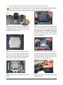
1-3-1 Installing the CPU
A. Locate the alignment keys on the motherboard CPU socket and the notches on the CPU.
Read the following guidelines before you begin to install the CPU:
• Make sure that the motherboard supports the CPU.
• Always turn off the computer and unplug the power cord from the power outlet before installing
the CPU to prevent hardware damage.
• Locate the pin one of the CPU. The CPU cannot be inserted if oriented incorrectly. (Or you may
locate the notches on both sides of the CPU and alignment keys on the CPU socket.)
• Apply an even and thin layer of thermal grease on the surface of the CPU.
• Do not turn on the computer if the CPU cooler is not installed, otherwise overheating and damage
of the CPU may occur.
• SettheCPUhostfrequencyinaccordancewiththeCPUspecications.Itisnotrecommended
thatthesystembusfrequencybesetbeyondhardwarespecicationssinceitdoesnotmeetthe
standard requirements for the peripherals. If you wish to set the frequency beyond the standard
specifications, please do so according to your hardware specifications including the CPU,
graphics card, memory, hard drive, etc.
Notch
Alignment KeyAlignment Key
Notch
LGA1150 CPU
LGA1150 CPU Socket
Pin One Corner of the CPU Socket
Triangle Pin One Marking on the CPU
6LISL-S_V1.1

- 13 - Hardware Installation
Step 1:
Gently press the CPU socket lever handle down
andawayfromthesocketwithyournger.Then
completely lift the CPU socket lever and the metal
load plate will be lifted as well.
Step 3:
HoldtheCPUwithyourthumbandindexngers.
Align the CPU pin one marking (triangle) with the
pin one corner of the CPU socket (or you may
align the CPU notches with the socket alignment
keys) and gently insert the CPU into position.
Step 5:
Push the CPU socket lever back into its locked
position.
Step 4:
Once the CPU is properly inserted, use one
hand to hold the socket lever and use the other
to lightly replace the load plate. When replacing
the load plate, make sure the front end of the
load plate is under the shoulder screw.
NOTE:
Hold the CPU socket lever by the handle, not the
lever base portion.
Step 2:
Remove the CPU socket cover as shown. Hold
your index finger down on the rear grip of the
socket cover and use your thumb to lift up the
front edge (next to the "REMOVE" mark) and
then remove the cover. (DO NOT touch socket
contacts. To protect the CPU socket, always
replace the protective socket cover when the
CPU is not installed.)
B. Follow the steps below to correctly install the CPU into the motherboard CPU socket.
Before installing the CPU, make sure to turn off the computer and unplug the power cord from
the power outlet power plug to prevent any damage to prevent damage to the CPU.

Hardware Installation - 14 -
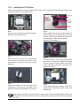
1-3-2 Installing the CPU Cooler
Follow the steps below to correctly install the CPU cooler on the motherboard. (The following procedure uses
Intel
®
boxed cooler as the example cooler.)
Use extreme care when removing the CPU cooler because the thermal grease/tape between the
CPU cooler and CPU may adhere to the CPU. Inadequately removing the CPU cooler may damage
the CPU.
Step 1:
Apply an even and thin layer of thermal paste on
the surface of the installed CPU.
Male Push
Pin
Female
Push Pin
The Top
of Female
Push Pin
Direction of the
Arrow Sign on
the Male Push
Pin
Step 2:
Before installing the cooler, note the direction of
the arrow sign on the male push pin. (Turning
the push pin along the direction of the arrow is
for removing the cooler, and the opposite
direction is for installing it..)
Step 3:
Place the cooler atop the CPU, aligning the
four push pins through the pin holes on the
motherboard. Push down on the push pins
diagonally.
Step 4:
You should hear a "click" when pushing down
each push pin. Check that the Male and Female
push pins are joined closely. (Refer to your CPU
cooler installation manual for instructions on
installing the cooler.)
Step 5:
After the installation, check the back of the
motherboard. If the push pin is inserted as the
picture above shows, the installation is complete.
Step 6:
Finally, attach the power connector of the CPU
cooler to the CPU fan header (CPU_FAN) on the
motherboard.

- 15 - Hardware Installation
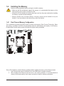
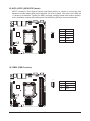
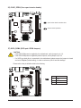
1-4-1 DualChannelMemoryConguration
This motherboard provides two DDR3 memory sockets and supports Dual Channel Technology. When
thememory is installed,the BIOS willautomatically detect thespecications and capacityof the memory.
Enabling Dual Channel memory mode will double the original memory bandwidth.
1-4 Installing the Memory
Read the following guidelines before you begin to install the memory:
• Make sure that the motherboard supports the memory. It is recommended that memory of the
same capacity, brand, speed, and chips be used.
• Always turn off the computer and unplug the power cord from the power outlet before installing
the memory to prevent hardware damage.
• Memory modules have a foolproof design. A memory module can be installed in only one
direction. If you are unable to insert the memory, switch the direction.
Due to CPU limitations, read the following guidelines before installing the memory in Dual Channel mode.
1. Dual Channel mode cannot be enabled if only one DDR3 memory module is installed.
2. When enabling Dual Channel mode with two or four memory modules, it is recommended that
memory of the same capacity, brand, speed, and chips be used for optimum performance.
DDR3_P0_B0
DDR3_P0_A0

Hardware Installation - 16 -
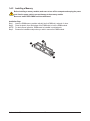
1-4-2 Installing a Memory
Before installing a memory module, make sure to turn off the computer and unplug the power
cord from the power outlet to prevent damage to the memory module.
Be sure to install DDR3 DIMMs on this motherboard.
Installation Step:
Step 1. Insert the DIMM memory module vertically into the DIMM slot, and push it down.
Step 2. Close the plastic clip at both edges of the DIMM slots to lock the DIMM module.
NOTE! For dual-channel operation, DIMMs must be installed in matched pairs.
Step 3. Reverse the installation steps when you wish to remove the DIMM module.
2
2
1

- 17 - Hardware Installation
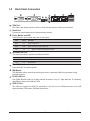
1-5 Back Panel Connectors
VGA Port
The video in port allows connect to video in, which can also apply to video loop thru function.
Serial Port
Connects to serial-based mouse or data processing devices.
Power Button and LED
Press this button to hard reset and power on the system.
Color Status Description
Green On System is powered on.
Green Blink System is in ACPI S1 state (sleep mode)
N/A Off
• System is not powered on or in ACPI S5 state (power off)
• System is in ACPI S4 state (hibernate mode)
ID Button and LED
Thisbuttonprovidestheselectedunitidcationfunction.
Color Status Description
Blue On Unitselectedforidentication.
N/A Off Noidentication.
Reset Button
Press this button to reset the system.
NMI Button
The NMI button allows a technician servicing the server to generate a NMI to the processor to help
solve server errors.
RJ-45 LAN Port
The Gigabit Ethernet LAN port provides Internet connection at up to 1 Gbps data rate. The following
describes the states of the LAN port LEDs.
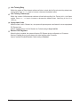
USB 2.0 Port
The USB port supports the USB 2.0 specification. Use this port for USB devices such as a USB
keyboard/mouse,USBprinter,USBashdriveandetc.

Hardware Installation - 18 -
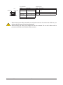
Link
Activity LED
Speed LED
10/100/1000 LAN Port
Link/Activity LED:I210 Speed LED:
State Description
Yellow On 1 Gbps data rate
Yellow Blink Identify 1 Gbps data
rate
Green On 100 Mbps data rate
Green Blink Identify 100 Mbps data
rate
Off 10 Mbps data rate
State Description
On Link bet ween system and net work or no
access
Blinking Data transmission or receiving is occurring
Off No data transmission or receiving is occurring
• Whenremovingthecableconnectedtoabackpanelconnector,rstremovethecablefromyour
device and then remove it from the motherboard.
• When removing the cable, pull it straight out from the connector. Do not rock it side to side to
prevent an electrical short inside the cable connector.

- 19 - Hardware Installation
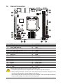
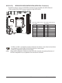
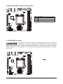
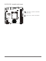
1-6 Internal Connectors
1) ATX1
2) P12V_AUX1
3) CPU0_FAN (CPU Fan)
4) SYS_FAN1 (System Fan)
5) SYS_FAN2 (System Fan)
6) SYS_FAN3 (System Fan)
7) PWR_DET
8) SATA0
9) SATA1
10) SATA2
11) SATA3
12) SATA4
13) FP_1
14) F_USB3
15) F_USB2_1
16) FP_VGA1
17) TPM
18) SGPIO_SATA
19) IPMB1
20) BMC_LED1
21) HDMI
22) BAT
23) CLRCMOS
24) BIOSRCVR
25) ME_UPDATE
26) CASE_OPEN
27) SATA_DOM4
28) CFG5
3
4
2
1
5
67
8
9
10
11
12
13
17
27
14
26
27
22
15
18
23
19
24
20
25
21
16
Read the following guidelines before connecting external devices:
• First make sure your devices are compliant with the connectors you wish to connect.
• Before installing the devices, be sure to turn off the devices and your computer. Unplug the power
cord from the power outlet to prevent damage to the devices.
• After installing the device and before turning on the computer, make sure the device cable has
been securely attached to the connector on the motherboard.

Hardware Installation - 20 -
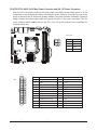
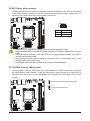
P12V_AUX1
12
24
1
13
ATX1
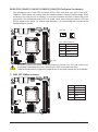
PinNo. Denition
13 3.3V
14 -12V
15 GND
16 PS_ON
17 GND
18 GND
19 GND
20 -5V
21 +5V
22 +5V
23 +5V
24 GND
PinNo. Denition
1 3.3V
2 3.3V
3 GND
4 +5V
5 GND
6 +5V
7 GND
8 Power Good
9 5VSB (stand by +5V)
10 +12V
11 +12V
12 3.3V
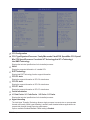
1/2) ATX1/P12V_AUX1 (2x12 Main Power Connector and 2x2 12V Power Connector)
With the use of the power connector, the power supply can supply enough stable power to all the
componentsonthemotherboard.Before connecting the power connector,rst makesurethepower
supply is turned off and all devices are properly installed. The power connector possesses a foolproof
design. Connect the power supply cable to the power connector in the correct orientation. The 12V
power connector mainly supplies power to the CPU. If the 12V power connector is not connected, the
computer will not start.
F_PANEL
F_PANEL
F_AUDIO
F_AUDIO
F_USB
COMB
MODEM
Smart Card Reader
SPDIF
AUX_IN
CD_IN
Secure Gigital /
Memory Stick
Serial ATA
F_USB
F_1394
CPU_FAN
SYS_FAN
PWR_FAN
NB_FAN
Power
WOL
SUR_CEN
IR/CIR
F_PANEL
F_PANEL
PWR_LED
CLR_CMOS
BIOS_WP
CLR_CMOS
BIOS_WP
CI
DPVRM
CLR_PWD
FDD
ATX
ATX_12V
IDE
IR
COMB
SPDIF_IO
F1_1394
F2_1394
GAME
SMB_CONN
F_AUDIO
(NEW)
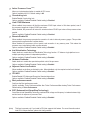
F1_1394
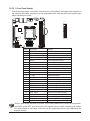
2 1
4 3
PinNo. Denition
1 GND
2 GND
3 +12V
4 +12V
Page is loading ...
Page is loading ...
Page is loading ...
Page is loading ...
Page is loading ...
Page is loading ...
Page is loading ...
Page is loading ...
Page is loading ...
Page is loading ...
Page is loading ...
Page is loading ...
Page is loading ...
Page is loading ...
Page is loading ...
Page is loading ...
Page is loading ...
Page is loading ...
Page is loading ...
Page is loading ...
Page is loading ...
Page is loading ...
Page is loading ...
Page is loading ...
Page is loading ...
Page is loading ...
Page is loading ...
Page is loading ...
Page is loading ...
Page is loading ...
Page is loading ...
Page is loading ...
Page is loading ...
Page is loading ...
Page is loading ...
Page is loading ...
Page is loading ...
Page is loading ...
Page is loading ...
Page is loading ...
Page is loading ...
Page is loading ...
Page is loading ...
Page is loading ...
Page is loading ...
Page is loading ...
Page is loading ...
Page is loading ...
Page is loading ...
Page is loading ...
Page is loading ...
Page is loading ...
Page is loading ...
Page is loading ...
Page is loading ...
Page is loading ...
Page is loading ...
Page is loading ...
Page is loading ...
Page is loading ...
Page is loading ...
Page is loading ...
Page is loading ...
Page is loading ...
Page is loading ...
Page is loading ...
Page is loading ...
Page is loading ...
Page is loading ...
Page is loading ...
Page is loading ...
Page is loading ...
Page is loading ...
Page is loading ...
Page is loading ...
Page is loading ...
Page is loading ...
-
 1
1
-
 2
2
-
 3
3
-
 4
4
-
 5
5
-
 6
6
-
 7
7
-
 8
8
-
 9
9
-
 10
10
-
 11
11
-
 12
12
-
 13
13
-
 14
14
-
 15
15
-
 16
16
-
 17
17
-
 18
18
-
 19
19
-
 20
20
-
 21
21
-
 22
22
-
 23
23
-
 24
24
-
 25
25
-
 26
26
-
 27
27
-
 28
28
-
 29
29
-
 30
30
-
 31
31
-
 32
32
-
 33
33
-
 34
34
-
 35
35
-
 36
36
-
 37
37
-
 38
38
-
 39
39
-
 40
40
-
 41
41
-
 42
42
-
 43
43
-
 44
44
-
 45
45
-
 46
46
-
 47
47
-
 48
48
-
 49
49
-
 50
50
-
 51
51
-
 52
52
-
 53
53
-
 54
54
-
 55
55
-
 56
56
-
 57
57
-
 58
58
-
 59
59
-
 60
60
-
 61
61
-
 62
62
-
 63
63
-
 64
64
-
 65
65
-
 66
66
-
 67
67
-
 68
68
-
 69
69
-
 70
70
-
 71
71
-
 72
72
-
 73
73
-
 74
74
-
 75
75
-
 76
76
-
 77
77
-
 78
78
-
 79
79
-
 80
80
-
 81
81
-
 82
82
-
 83
83
-
 84
84
-
 85
85
-
 86
86
-
 87
87
-
 88
88
-
 89
89
-
 90
90
-
 91
91
-
 92
92
-
 93
93
-
 94
94
-
 95
95
-
 96
96
-
 97
97


Gigabyte GA-6LISL User manual
- Category
- Server/workstation motherboards
- Type
- User manual
Ask a question and I''ll find the answer in the document
Finding information in a document is now easier with AI
Related papers
-
Gigabyte MW31-SP0 Owner's manual
-
Gigabyte GA-7PESH3 User manual
-
-
Gigabyte GA-7PESH2 User manual
-
-
-
Gigabyte GA-6LXSV User manual
-
-
-
