GROHE K4 32 072 User manual
- Category
- Sanitary ware
- Type
- User manual
This manual is also suitable for
Page is loading ...

1
S.v.p remettre cette instruction à l'utilisateur de la robinetterie!
Entregue estas instrucciones al usario final de la grifería!
Please pass these instructions on to the end user of the fitting!
32 072
32 074
Page is loading ...
Page is loading ...

4
English
Application
Operation is possible in conjunction with:
• Pressurized storage heaters
• Thermally controlled instantaneous heaters
• Hydraulically controlled instantaneous heaters
Operation with low-pressure storage heaters (displacement water
heaters) is not possible.
Specifications
• Max. flow 8.3 L/min or 2.2 gpm/60 psi
• Flow pressure
- min. 7.25 psi
- recommended 14.5 - 72.5 psi
- greater than 72.5 psi, fit pressure reducing valve
• Max. operating pressure 145 psi
• Test pressure 232 psi
• Temperature
- max. (hot water inlet) 176 °F
• Water connection cold - RH hot - LH
• Deck thickness max. 2 3/8"
• Non reversible cartridge
Notes:
- Major pressure differences between cold and hot water supply
should be avoided.
- To be installed according to local codes and regulations.
- This faucet is not intended for the use with portable appliances.
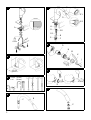
Installation
Flush pipes thoroughly!
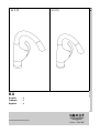
Mount sink faucet, see fig. [1].
Refer to the dimensional drawings on page 1.
Note:
If brace (A) is omitted, deck thickness can be increased by 1 3/4" to
a total of 2 3/8".
The following lever positions can also be obtained, see fig. [2].
Connect sink faucet, see figs. [1] and [3].
- Cold water connection (marked blue) = right
- Hot water connection (marked red) = left
Avoid cross connection. The cartridge is not reversible.
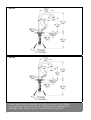
Connect spray hose (B), see figs. [4] and [5].
1. Feed the spray hose (B) through the spout (C), see fig. [4].
2. Feed the spray hose (B) through the faucet body from above and
fit spout (C) so that it snaps into place, see fig. [5].
3. Fit one side of the stop (E) and spring (F) over the spray
hose (B).
4. Pass the end of the spray hose (B) through the other hole in the
stop (E).
5. Install the snap coupling (G) with O-ring (G1) on the end of the
spray hose (B) and tighten by hand.
6. Pull the sleeve (G2) of the snap coupling (G) downwards and fit
to the union (H).
To ensure that the shower head (D) is correctly seated when
inserted, cam (D1) on the handspray must engage in
groove (C1) on the spout.
Open cold and hot-water supply and check connections for
leakage!
Operation (Lever handle position on right side)
Slide lever to right = open (water flow)
Slide lever to left = closed
Slide lever towards front = cold water
Slide lever towards back = hot water
Flow rate limiter
This faucet is fitted with a flow rate limiter, permitting an infinitely
individual variable reduction of the flow rate.
The highest possible flow rate is set by the plant before despatch.
The use of flow rate limiters in combination with hydraulic
instantaneous water heaters is not recommended.
To activate see “Replacing the cartridge” point 1 and 2,
figs. [6] and [7].
Maintenance
Inspect and clean all parts, replace as necessary and grease with
special grease.
Shut off cold and hot water supply!
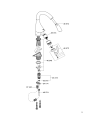
I. Replacing the cartridge, see fig. [6].
1. Remove fixing screw (J) and pull off lever (K).
2. Pull off cap (L) and insert (M).
3. Unscrew threaded ring (N) by using a socket spanner 32mm.
4. Change the complete cartridge (O).
Assemble in reverse order.
Observe the correct installation position!
Make sure that the cartridge seals engage in the grooves and the
locating pins at the base of the cartridge slot into the apertures on
the housing.
II. Flow straightener, see fig. [8].
Unscrew and clean flow straightener (P).
Assemble in reverse order.
Replacement parts, see page 2 ( * = special accessories).
Care
Instructions for care of this faucet will be found in the Limited
Warranty supplement.
Page is loading ...
Page is loading ...
Page is loading ...
Page is loading ...
Page is loading ...
Page is loading ...
Page is loading ...
Page is loading ...
Page is loading ...

Grohe Canada Inc.
1226 Lakeshore Road East
Mississauga, Ontario
Canada, L5E 1E9
Technical Services
Services Techniques
Phone/Tél: 905/271-2929
Fax/Télécopieur: 905/271-9494
Grohe America Inc.
241 Covington Drive
Bloomingdale, IL
60108
U.S.A.
Technical Services
Phone: 630/582-7711
Fax: 630/582-7722
-
 1
1
-
 2
2
-
 3
3
-
 4
4
-
 5
5
-
 6
6
-
 7
7
-
 8
8
-
 9
9
-
 10
10
-
 11
11
-
 12
12
-
 13
13
-
 14
14
-
 15
15


GROHE K4 32 072 User manual
- Category
- Sanitary ware
- Type
- User manual
- This manual is also suitable for
Ask a question and I''ll find the answer in the document
Finding information in a document is now easier with AI
in other languages
- français: GROHE K4 32 072 Manuel utilisateur
- español: GROHE K4 32 072 Manual de usuario
Related papers
-
GROHE 32283SD0 Installation guide
-
-
-
-
-
-
GROHE 38505000 User manual
-
-
-