KitchenAid KUDC03FVBL3 Installation guide

Category
Dishwashers
Type
Installation guide
KitchenAid ®
iNSTALLATiON iNSTRUCTiONS
UNDERCOUNTER DISHWASHER
iNSTRUCTiONS D'INSTALLATION
LAVE-VAISSELLESOUS PLAN DE TRAVAIL
Table of Contents ................................... 2
Table des matieres .................................. 27
W10056407A
Table of Confenfs
Dishwasher Safety ................................. 2
Installation Requirements ........................... 3
Tools and Parts ................................... 3
Location Requirements ............................ 4
Drain Requirements ............................... 6
Water Supply Requirements ........................ 6
Electrical Requirements ............................ 6
Installation instructions ............................. 7
Prepare Cabinet Opening--Existing Utilities ........... 7
Prepare Cabinet Opening--New Utilities .............. 7
Prepare and Route Water Line ...................... 8
install Drain Hose ................................ 9
Install Moisture Barrier (on some models) ........... 10
Prepare Dishwasher ............................. 11
Make Power Supply Cord Connection ............... 12
Determine Cabinet Opening ....................... 13
installation instructions (cont.}
Install the Door Handle (on some models) ........... 14
Custom Panel Dimensions ........................ 14
Install Custom Panel - Option 1 .................... 15
Install Custom Panel - Option 2 .................... 16
Choose Attachment Option ........................ 17
Move Dishwasher Into Cabinet Opening ............. 18
Connect to Water Supply ......................... 20
Connect to Drain ................................ 21
Make Direct Wire Electrical Connection .............. 21
Secure Dishwasher in Cabinet Opening ............. 23
Complete installation ............................. 24
Check Operation ................................. 25
If Dishwasher Does Not Operate ................... 25
Additional Tips .................................. 25
DISHWASHER SAFETY
Your safety and the safety of others are very important.
We have provided many important safety messages in this manual and on your appliance. Always read and obey all safety
messages.
This is the safety alert symbol.
This symbol alerts you to potential hazards that can kill or hurt you and others.
All safety messages will follow the safety alert symbol and either the word "DANGER" or "WARNING."
These words mean:
You can be killed or seriously injured if you don't immediately
follow instructions.
You can be killed or seriously injured if you don't follow
instructions.
All safety messages will tell you what the potential hazard is, tell you how to reduce the chance of injury, and tell you what can
happen if the instructions are not followed.
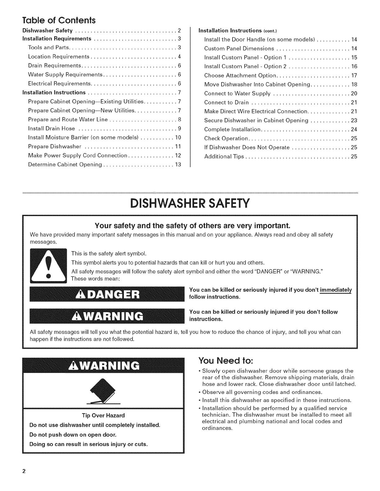
Tip Over Hazard
Do not use dishwasher until completely installed.
Do not push down on open door.
Doing so can result in serious injury or cuts.
You Need to:
, Slowly open dishwasher door while someone grasps the
rear of the dishwasher. Remove shipping materials, drain
hose and lower rack. Close dishwasher door until latched.
, Observe all governing codes and ordinances.
, Install this dishwasher as specified in these instructions.
, Installation should be performed by a qualified service
technician. The dishwasher must be installed to meet all
electrical and plumbing national and local codes and
ordinances.
2
iNSTALLATiON REQUIREMENTS
Tools and Parts
Gather the recommended tools and parts before starting
installation. Read and follow the instructions provided with
any tools listed here.
All Installations
Tools needed:
_,. /_ z_2 Flat-bade
ruers I screwdriver
5/16" and 1/4" _ ' UL listed or CSA
nut drivers or _f approved twist-on ff
hex sockets _ wire connectors* v
10" adjustable wrench 5/8" open -end
that opens to wrench
1.18" (2.9 cm) _.
If installing custom front panels, _y
Torx T15 screwdriver _'
-Must be the proper size to connect your household wiring
to 16-gauge wiring in dishwasher
Other useful items you may need:
F ash ight _ Bathtowe _
Parts supplied:
@ sCrows
r Green
Make sure all these parts are included in the literature package.
Parts needed:
90° ElboW fitting with 3/8_, Tefl0n_ tape Or pipe
N.RT, external threads (the joint Compou[
other end mUSt fit yOUr Water
Supply line)
4 #10 x 1/2" wood screws (if installing custom front panels)
® Teflon is a registered trademark of E.I. Du Pont de Nemours and Company.
TORX is a registered trademark of Acument Intellectual Properties, LLC.
Other parts you may also need:
1i " 2"
/2-
1!38:1_5:0em) I Masking or
i Screw-type
[damps_3max)J
NOTE: Parts available for purchase Jnplumbing supply stores.
Check local codes. Check existing electrical supply. See
"Electrical Requirements" section. It is recommended that
electrical connections be made by a licensed electrical installer.
In addition, for first=time installations
Tools needed:
Iwith 1/2 513/4 7//,
_and11!2 h01e_]
saw bits ...................
Parts needed:
C0ppei tubing (3/8!'
OiD. suggested) o[
flexible braided
W_e
see "Electrical Requirements" Section
Fo[ Direct wire: For Power supply
i use UL listed or Card: useUL
CSA approved listed power
i st[ain;re!ief to Supply cord kit
i fit7/8 (2.2cm) marked for use
hoe with dishWasher
Additional parts supplied with top=venting models only:
Torx.so 10x , ,hex a scewsi
Additional parts supplied with certain models only:
I Bottom Sound pad (located I Moisture bairier tape
[in lower rack) [ l
Make sure all these parts are included in the literature package.
If parts are not included, call 1-800-422-1230.
Location Requirements
Grounded electrical supply required.
Do not run drain lines, water lines or electrical wiring where
they can interfere with or contact dishwasher motor or legs.
The location where the dishwasher will be installed must
provide clearance between motor and flooring. Motor
should not touch the floor.
Do not install dishwasher over carpeted flooring.
Shelter dishwasher and water lines leading to dishwasher
against freezing. Damage from freezing is not covered by
the warranty.
A side panel kit is available from your dealer for installing
your dishwasher at the end of your cabinetry.
A moisture barrier accessory (Part Number 4396277) is
available from your dealer for installing underneath the
countertop, but is not required. Call 1=800=422=1230 to
order.
Check location where dishwasher will be installed. The
location must provide:
easy access to water, electricity and drain.
convenient access for loading and unloading dishes.
Corner locations require a 2" (5.1 cm) minimum
clearance between the side of the dishwasher door
and the wall or cabinet.
square opening for proper operation and appearance.
cabinet front perpendicular to floor.
level floor. (If floor at front of opening is not level with
floor at rear of opening, shims may be needed to level
dishwasher.)
Helpful Tip: Be sure to accurately measure dimensions
and ensure dishwasher is level if the floor in the
dishwasher opening is uneven (example: Flooring
extends only partway into opening).
NOTE: To avoid shifting during dishwasher operation,
shims must be securely attached to the floor.
If dishwasher will be left unused for a period of time or in a
location where it may be subject to freezing, have it
winterized by authorized service personnel.
Make sure pipes, wires and drain hose are within the
shaded area shown in the "Product and Cabinet
Opening Dimensions" section.
4
Product and Cabinet Opening Dimensions
J
*Insulation may be compressed
(not used on al models:_
NOTE: Shaded area of cabinet walls show where
utility connections may be installed.
*Measured from the lowest point on the
underside of countertop. May be reduced to
33 7/8" (86 cm) by removing wheels from
dishwasher.
**Minimum, measured from narrowest point of /
opening.
Check that all surfaces have no protrusions
that would prohibit dishwasher installation.
cco
_0. /
Drain Requirements
, A new drain hose is supplied with your dishwasher.
if this is not long enough, use a new drain hose with a
maximum length of 12' (3.7 m) (Part Number 3385556)
that meets all current AHAM/IAPMO test standards, is
resistant to heat and detergent, and fits the 1" (2.5 cm)
drain connector of the dishwasher.
* Make sure to connect drain hose to waste tee or disposer
inlet above drain trap in house plumbing and 20"
(50.8 cm) minimum above the floor. It is recommended
that the drain hose either be looped up and securely
fastened to the underside of the counter, or be connected
to an air gap.
Make sure to use an air gap if the drain hose is connected
to house plumbing lower than 20" (50.8 cm) above
subfloor or floor.
Use 1/2" minimum I.D. drain line fittings.
If required, the air gap should be installed in accordance
with the air gap installation instructions. When you are
connecting the air gap a rubber hose (not provided) will
be needed to connect to the waste tee or disposer inlet.
Wafer Supply Requiremenfs
* A hot water line with 20-120 psi (138-862 kPa) water
pressure can be verified by a licensed plumber.
* 120°F (49°C) water at dishwasher.
* 3/8" O.D. copper tubing with compression fitting or
flexible braided water supply line (Part Number
4396897RP)
NOTE: 1/2" minimum plastic tubing is not recommended.
* A 90° elbow with 3/8" N.RT. external pipe threads on one
end.
* Do not solder within 6" (15.2 cm) from water inlet valve.
Eiecfrical Requiremenfs
Be sure that the electrical connection and wire size are
adequate and in conformance with the National Electrical
Code, ANSI/NFPA 70 - latest edition and all local codes and
ordinances.
A copy of the above code standards can be obtained from:
National Fire Protection Association
One Batterymarch Park
Quincy, MA 02269
You must have:
120-volt, 60 Hz, AC-only, 15 or 20 amp, fused electrical
supply.
* copper wire only.
We recommend:
* a time-delay fuse or circuit breaker.
* a separate circuit.
if connecting dishwasher
with a power supply cord:
, Use UL listed power supply cord kit (Part Number
4317824) marked for use with dishwasher.
Power supply cord must plug into
a grounded 3 prong outlet, located in
the cabinet next to the dishwasher
opening. Outlet must meet all local
codes and ordinances.
if connecting dishwasher with direct wiring:
* Use flexible, armored
or nonmetallic
sheathed, copper wire
with grounding wire
that meets the wiring requirements for your home and
local codes and ordinances.
* Use a UL listed or CSA approved strain relief.
iNSTALLATiON iNSTRUCTiONS
Electrical Shock Hazard
Disconnect electrical power at the fuse box or circuit
breaker box before installing dishwasher.
Failure to do so can result in death or electrical shock.
DisconneCt electrical power at the fuse box or Circuit !
breaker box before installing dishwash
Yes _FoIIow instructions inthe "Prepare cabinet
Opening_Existing Utilities', section!
No _FoIIOW inStruCtions in the ,Prepare Cabinet
Opening_New uti!!ties Sect!0nl
Existing Utility hookups g t ity hookups
Water line
Prepare Cabinet OpeningmExisting
Utilities
If the water line and the cable extend to the locations
shown, proceed to the "Install Drain Hose" section. If they
do not reach far enough, follow the instructions in the
"Prepare Cabinet Opening--New Utilities" section.
Prepare Cabinet OpeningmNew
Utilities
Prepare and route the electrical supply
What type of electrical
connection will you use? L
c:_ _ P0wer Supply Cord:
Follow Option A inStructions
Direct Wire:
FOllow option B instructions
Option A, Power Supply Cord:
NOTE: A grounded 3 prong outlet is required inside a
cabinet next to the dishwasher cabinet opening.
Drill a 1 1/2" (3.8 cm) hole in cabinet side or rear.
See product and cabinet opening dimensions.
7
Woodcabinet:Sandholeuntilsmooth.
Metalcabinet:Coverholewithgrommetincludedwith
powersupplycordkit.
OptionB, Direct Wire:
Helpful "lip: Wiring the dishwasher will be easier if you
route the cable into the cabinet opening from the right side.
Drill a 3/4" (1.9 cm) hole in right-hand cabinet side or rear.
See product and cabinet opening dimensions.
Wood cabinet: Sand the hole until smooth.
Metal cabinet: Cover hole with grommet (not provided).
8
Route cable from power supply through cabinet hole (cable
must extend to the right front side of cabinet opening).
Tape cable to the floor in area shown. This will prohibit
cable from moving when dishwasher is moved into
cabinet opening.
Prepare and Roule Waler Line
Helpful Tip: Routing the water line through the left side
of cabinet opening will make water connection easier.
Drill a 1/2" (1.3 cm) hole in the cabinet side or rear.
Measure overall length of copper tubing or flexible
braided water supply line. Attach to the hot water line
using a connection configuration that is in compliance
with local codes and ordinances. The water line to the
dishwasher should have a manual shutoff valve.
Slowlyroutewatersupplylinethroughholeincabinet.
(Ifusingcoppertubing,itwillbendandkinkeasily,sobe
gentle.)Itshouldbefarenoughintothecabinetopening
toconnectittothedishwasherinletonthefrontleft
sideofthedishwasher.
Slowlyturnwatershutoffvalveto "ON"position.Flush
waterintoashallowpanuntilcleartogetridofparticles
thatcouldclogtheinletvalve.Turnshutoffvalveto
"OFF"position.
iiii_if_i{_i{_i{_i_iiiiii_iii_iii_iiiiii_i_iiiiiii_i_ii_iii_i_i_ii_i_iiiiiii_iiiiiii_iiiiii_iiiiiiiB_);_;ii_);_;ii_ii_i_ii_i_ii_i_ii_i_ii_i_);i_;i_;;ii;i_;ii_);i_;i;i_ii_i_ii_i_ii_i_ii_i_ii_i;_i;i_;;ii;i_;;i;iiIi_;i_;;i_);_;ii_);_ii¸i_;i_;i_i;;ii;i_;ii_ii_i_ii_i_ii_i_ii_i_ii_i_ii_i_ii_i_ii_i_ii_i_ii_i_ii_i_ii_i_ii_i_ii_i_ii_i_ii_i_ii_i_ii_i_ii_i_ii_i_ii_i_ii_i_ii_i_ii_i_ii_i_ii_i_ii_i_ii_i_ii_i_ii_i_ii_i_ii_i_ii_i_ii_i_ii_i_ii_i_ii_i_ii_i_ii_i_ii_i_i{_ii)y
InsfallDrain Hose
IMPORTANT: Always use a new drain hose. Check local
codes to determine if an air gap is required.
If needed, drill a 1 1/2" (3.8 cm) diameter hole in cabinet
wall or side of the opening closest to the sink.
Route drain hose as shown through hole in cabinet to the
front center of opening where drain connection will be
made. Tape drain hose to the floor in area shown. This will
prohibit it from moving when dishwasher is moved into
cabinet opening.
IMPORTANT: The drain hose connection of the disposer or
a waste tee must be made before the drain trap and at
least 20" (50.8 cm) above the floor where the dishwasher
will be installed.
Helpful Tip: To reduce vibration of the hose, keep the hose
away from the floor.
Option A, Waste disposer - no air gap
i iii
Drai
1. Using a hammer and screwdriver,
knock plug into disposer.
2. Use needle nose pliers to remove
plug.
3. Attach drain hose to disposer inlet
with large silver drain hose clamp
(provided). Use pliers to squeeze
clamp open and move into position.
Option B, No waste disposer - no air gap
1.Connect black end of of drain hose to
waste tee and cut if needed.
(Do not cut ribbed section.)
2. Attach black end of drain hose to waste
tee with a large silver drain hose clamp
(provided). Use pliers to squeeze clamp
open and move into position. If the drain
hose was cut use a 1 1/2" to 2" (3.8 to
5 cm) screw-type clamp (not provided).
Option C, Waste disposer - with air gap
Drain trap
1. Using a hammer and screwdriver,
knock plug into disposer.
2. Use needle nose pliers to remove
plug.
3. Connect black end of drain hose to air
gap and cut if needed. (Do not cut
ribbed section.)
4.
5.
Attach drain hose to air gap with large
silver drain hose clamp (provided).
Use pliers to squeeze clamp open and
move into position. If the drain hose
was cut, use a 1 1/2" to 2"(3.8 to
5 cm) screw-type clamp (not
provided).
Use a rubber hose (not provided) with
screw-type clamps (not provided) to
connect from air gap to disposer inlet.
Option D, No waste disposer - with air gap
2.
3.
Connect black end of drain hose to air
gap and cut if needed. (Do not cut
ribbed section.)
Attach drain hose to air gap with large
silver drain hose clamp (provided).
Use pliers to squeeze clamp open and
move into position. If the drain hose
was cut, use a 1 1/2" to 2"(3.8 to 5 cm)
screw-type clamp (not provided).
Use a rubber hose (not provided) with
screw-type clamps (not provided) to
connect from waste tee to air gap.
Install Moisture Barrier
(on some models)
I
Moisture
barrier
I
1. Make sure the area under the cabinet is clean and dry
for installation of the moisture barrier.
2. Remove the backing of the moisture barrier and apply
to underside of the countertop along the front edge of
the counter.
10
Prepare Dishwasher
Tip Over Hazard
Do not use dishwasher until completely installed.
Do not push down on open door.
Doing so can result in serious injury or cuts.
Excessive Weight Hazard
Use two or more people to move and install
dishwasher.
Failure to do so can result in back or other injury.
Helpful Tip: Place cardboard under dishwasher until installed
in cabinet opemng to avoid damaging floor covering. Do not
use door panel as a work table without first covering with a
towel to avoid scratching the door panel.
Using two or more people, grasp sides of dishwasher door
frame and place dishwasher on its back.
Using a 1/4" hex head socket, nut driver or Phillips
screwdriver, remove two screws attaching access panel
and lower panel to dishwasher. Do not remove tech
sheet from access panel.
Apply Teflon ® tape or pipe joint compound to 90 ° elbow
fitting (not provided). Wrap tape around coarse threads
two to four times to prohibit leaks.
Connect 90° elbow fitting to water inlet valve. Using a
wrench, tighten elbow until snug, and be sure that it
faces to the rear.
Using a 1/4" hex head socket, nut driver or Phillips
screwdriver, remove terminal box cover. Retain for
later use.
11
InstallaULlistedorCSAapprovedstrainrelief.Makesure
screwheadsarefacingtotheleftwhentighteningconduit
nut.Strainreliefisprovidedwiththepowersupplycordkit.
connection will you use? [ __
Power Supply Cord:
Follow Option A instructions
.................................................................................
Make Power Supply Cord Connection
Option A, Power Supply Cord:
Route cord so that it does not touch dishwasher motor
to lower part of dishwasher tub. Pull cord through strain
relief in terminal bow. Take notice when installing or
removing the dishwasher in order to reduce the chance
of damaging the power supply cord.
Select UL listed or CSA approved twist-on wire connectors
(included with power supply cord kit) rated to connect
your household wiring to 16-gauge dishwasher wiring.
Electrical Shock Hazard
Electrically ground dishwasher.
Connect ground wire to green ground connector
in terminal box.
Do not use an extension cord.
Failure to follow these instructions can result in
death, fire, or electrical shock.
-- _ _--
III I tt %::,#///!_ < _ar--Wl re sh
Remove the green grounding screw and place through
the ring terminal of the green ground wire. Reattach and
tighten the green screw.
NOTE: Twist on wire connector. Gently tug on wires to
be sure both are secured.
Connect wires black to black and white to white, using
UL listed or CSA approved twist-on wire connectors
(included with power supply cord kit).
)
12
Ifneeded,seewebsiteforanimatedrepresentationof
thisstep.Visitwww.kitchenaid.comunderFAQtab.
Tightenstrainreliefscrewstosecurecord.
Placewiresinsideterminalbox.Inserttabsonleftside
ofcover.Makesurewiresaretuckedinsidebox.Close
coverensuringwiresarenotpinched.Use1/4"nut
driverandpreviouslyremovedscrewtosecurecover.
NOTE:Donotplugintooutletuntilinstructedtodoso.
Defermine Cabinet Opening
Measure height of cabinet opening from underside of
countertop to floor where dishwasher will be installed
(you will need to measure the lowest point on the
underside of the countertop and the highest point on the
floor). Refer to "Dishwasher Height Adjustment Chart"
for wheel position and the number of turns needed.
Cabinet I Wheel Number of turns
Opening height position on front leg
33 7/8'i (86.0 Cm) I remove I the way up
|
34 1/4" (87cm) . 2 . 5
m
34 1/2" (87:6 cm) 3 0
J
NOTE: If the minimum cabinet opening height is less than
34"(86.4 cm), the rear wheels can be removed for
additional clearance. This will allow the dishwasher to fit
into a 33 7/8" (86 cm) high cabinet opening, but the
dishwasher will be more difficult to move. (Measurements
are approximate. Wheels and legs are preset at the
factory for 34 1/2" [87.6 cm].)
2
Adjust wheels and legs ......
!
Turn both leveler legs to the same height. Put wheels in
the required position determined from "Dishwasher
Height Adjustment Chart."
)
13
Built-upfloorsKitchenfloorheightishigherthan
cabinetopening.)Example:Kitchenfloortiledoesnot
extendintocabinetopening.Addshimsasneededinthe
areashowntobringthedishwasherupto34"(86.4cm)
belowthecountertop.
NOTE:Shimsmustbesecurelyattachedtofloortoavoid
movementwhenthedishwasherisinuse.
Mountingstud
Handle
Setscrew
(inbottom
of )
Allen
IMPORTANT:Donotscratchthefrontpanelduringthis
procedure.
Removethedoorhandleandhardwarebagcontaining
thesetscrewsandAllenwrenchfromthecardboardbox.
Setscrewsarealreadyinstalledinthehandle.Place
handleonmountingstudswiththesetscrewsfacing
down.Pushthedoorhandletightlyagainstthedoor.
InserttheshortendoftheAllenwrenchintothe
setscrews.Tightenthesetscrews1/4turnpastsnug.
RetainAllenwrenchwithInstallationInstructions.
IMPORTANT:Youneedtoknowwhatcontrolpanelison
yourdishwasherbeforeyouorderyourcustomdoor
panel.
Dishwashers with control panel on
top custom panel dimensions
23 1/2" /" _ -_Z.30 3/16" (76.7 cm)
7 cm'
*This dimension is for 4" (10.2 cm) toe kick. If the
installation needs a higher toe kick, adjust the height
of the wood panel accordingly. Not recommended for
toe kicks greater than 6" (15.2 cm).
Follow directions under Option 1 of "Install custom
panel" section.
Dishwashers with control panel on
front custom panel dimensions
(19.1 mm)
(3.2 mm)
mm)
*This dimension is for 4" (10.2 cm) toe kick. If the
installation needs a higher toe kick, adjust the height
of the wood panel accordingly. Not recommended for
toe kicks greater than 6" (15.2 cm).
Follow directions in Option 2 of "Install custom panel"
section.
14
InstallCustom Panel - Option ]
(Models KUDG40FVPA, KUDG50FVPA, KUDE60FVPA,
and KUDE70FVPA}
NOTE: The handle for the custom panel is not included.
IMPORTANT: If the handle is attached from the back of
the custom panel, the screw holes should be countersunk
for the screws heads to be flush with the panel. If the
handle is attached to the front of the custom panel, the
screw lengths cannot exceed the panel thickness. For
more information on KitchenAid custom handle selection,
refer to the KitchenAid Catalog, visit
www.kitchenaid.com, or call 1-8OO-422-1230.
NOTE: A customer-supplied full front panel must weigh
no more than 16 Ibs (7.3 kg) and must be made to
specific dimensions. It is recommended that a
cabinetmaker cut the custom panel because of the
precise dimensions needed.
NOTE: All mounting hardware supplied is for a 3/4"
(19.1 mm) thick wood panel. If a thinner wood panel, or
materials other than wood are used, it is the consumer's
responsibility to obtain the proper length screws and
adjust the pilot holes accordingly.
IMPORTANT: Use a moisture resistant sealer on both
sides and all edges of the panel to avoid damage from
humidity.
1 ICustom panel installation
-:J Dishwashers with control |
panel on the top ....
23 1/2" _"'_"30 3/16" (76.7 cm)
7 cm'
*This dimension is for 4" (10.2 cm) toe kick. If the
installation needs a higher toe kick, adjust the height
of the wood panel accordingly. Not recommended for
toe kicks greater than 6" (15.2 cm).
With a TORX _)screwdriver, remove three screws from both
sides, as shown; hold the outer panel up while removing
the screws. Save screws for reinstallation.
Dishwashers with control panel on
top custom panel dimensions
....J
3 screws
per side
outer F
Gently set outer panel aside. Lay the customer-supplied
custom panel face down on a covered, non-scratching
surface.
9 29/32"
(25.2 cm)
p edge
Measure 9 29/32" (25.2 cm) from top edge and mark a line
on the back of customer-supplied custom panel. Position the
outer panel on the back of the customer-supplied custom
panel as shown, so that the top holes in the outer panel are
on the line, and both panels are centered side to side.
holes
Mark all four hole locations; remove outer panel. Drill 3/32"
pilot holes 1/2" (13 mm) deep in customer-supplied custom
panel. Place the outer panel on the back of the customer-
supplied custom panel; align holes.
15
Attachouterpaneltobackofcustomer-suppliedcustom
panelwiththefour#10-16x3/8"hexheadscrewssupplied
intheliteraturepackage.Attachthehandle.Thehandle
shouldbecenteredonthefrontofthecustomer-supplied
custompanelintheareashown.
IMPORTANT:Screwheadsmustbeflushwithbackof
customer-suppliedcustompanel.
i
R edges
3 screws
each side Customer-supplied
panel
J
Attach the panel assembly to the door by reinstalling the
three screws on each side; do not tighten completely. This
reinstallation of the three screws will hold the panel
assembly in place on the door frame.
top
edges
Drill through
these holes
Customer-supplied
panel
i,,_
Align the top edge of the customer-supplied custom
panel with the top of the console.
Drill two 3/32" pilot holes 1/2" (13 mm) deep, into the
customer-supplied custom panel, through the holes in the
top corners on the inner panel, as shown.
16
top
edges
)rill through
these holes
Customer-supplied
panel
Install the two #8-18 x 1 3/8" screws from
the literature package in the top corners of the inner
panel. Tighten the six side screws reinstalled in Step 6.
Install Custom Panel - Option 2
(Models KUDCO21V and KUDS2OIV)
All models require an accessory option to attach custom
panels. Kit Number 8171555 (black), 8171556 (white) or
8171557 (biscuit) are available. To order, call customer
service at 1-8OO-444-1230.
NOTE: A custom full front panel must weigh no more
than 14 Ibs (6.3 kg) and must be made to specific
dimensions. It is recommended that a cabinetmaker cut
the custom panel because of the precise dimensions
needed.
IMPORTANT: Use a moisture resistant sealer on both
sides and all edges of the panel to avoid damage from
humidity.
NOTE: These dimensions are for frameless custom panel
models with a 4" (10.2 cm) console only.
Custo m pa neI insta IIatio n -
1J Dishwashers with control 1
panel on the front | ...................
/
23 3/8" /'_1"_,25 29/32" (65.8 cm)
(65.8 cm) _____.._
mm)
(3.2 mm)
mm)
*This dimension is for 4" (10.2 cm) toe kick. If the
installation needs a higher toe kick, adjust the height
of the wood panel accordingly. Not recommended for
toe kicks greater than 6" (15.2 cm).
With a TORX _ screwdriver, remove three screws from
both sides, as shown; hold the outer panel up while
removing the screws. Save screws for reinstallation.
Dish:W erswi controlPanei
-= front custom panel dimensions
3screws
per side
outer
Gently set outer panel aside. Lay the cutomer-supplied
custom panel face down on a non-scratching surface.
Position the outer panel on the back of the customer-
supplied custom panel as shown; make sure top edge of
the outer panel is aligned with the top edge of the
customer-supplied custom panel, and both panels are
centered side to side.
holes
Mark all four hole locations; remove outer panel and drill
3/32" pilot holes 1/2" (13 mm) deep, in customer-supplied
custom panel. Place the outer panel on the back of the
customer-supplied custom panel and align holes. Attach
outer panel to back of customer-supplied custom panel
with four #10 x 1/2" wood screws (not supplied). If the
customer-supplied custom panel is less than 3/4" (1.9 cm)
thick where the screws are attached, shorter screws maybe
required.
i
R edges
3 screws
each side Customer-supplied
panel
Attach the panel assembly to the door by reinstalling the
three screws on each side.
Choose Affechrnenf Option
Excessive Weight Hazard
Use two or more people to move and install
dishwasher.
Failure to do so can result in back or other injury.
Using two or more people, stand the dishwasher up.
Option 1, Countertop attachment:
brackets
i i ii
iMPORTANT: The dishwasher must be secured to the
cabinet. There are two brackets on top of the dishwasher
that can be attached to the countertop if it is wood,
laminate or other similar surfaces. If your countertop is
marble, granite or other hard surface the brackets may
be moved to the sides of the dishwasher.
NOTE: Do not attach the dishwasher. This will be done
later.
Option 2, Dishwasher side attachment:
tabs
To remove the brackets from the top, flatten tab at back
of brackets with pliers, and pull the brackets out of the
slots.
17
Breakofftheendofthebracketalongthescoredline.
Withanotherpersonholdingtherearofthedishwasher
tokeepitfromtipping,opendishwasherdoorandplace
toweloverpumpassemblyandsprayarmofdishwasher.
Thiswillkeepscrewsfromfallingintopumpareawhen
youaresecuringdishwashertocabinet.
plastic
button
Push the plastic buttons out of the side of the tub.
NOTE: Save the buttons to cover the holes after
dishwasher is installed.
Push bracket into slot on the side of dishwasher, and
bend tab in toward the side of the dishwasher so that it
keeps the bracket in place. Repeat this step for the other
side of the dishwasher.
NOTE: Do not attach the dishwasher. This will be done
later.
Move Dishwasher into Cabinet
Opening
Excessive Weight Hazard
Use two or more people to move and install
dishwasher.
Failure to do so can result in back or other injury.
Using two or more people, stand dishwasher upright.
NOTE: Do not install kickplate until instructed.
IMPORTANT: Double check correct placement of utilities.
Grasp the sides of the dishwasher at the edges of the
door panel. Tilt dishwasher backwards on wheels and
move dishwasher close to cabinet opening.
NOTE: Do not push on the front of the panel or on the
console. Panel or console may dent.
Helpful Tip: Temporarily tape utilities to the floor in the
locations shown to prohibit them from moving when
dishwasher is moved into the cabinet opening.
18
Checkthatwaterlineisontheleftsideofopeningand
drainhoseisnearthecenterofthecabinetopening.
Withanotherpersonholdingthedishwashertoavoidit
fromtipping,openandclosethedoorafewtimes.Ifthe
doorclosesorfallsopenunderitsownweight,thedoor
tensionwillneedtobeadjusted.
Toadjustthedoorspringtension,unhookthespring
fromtherearlegofdishwasher.
Usinga5/16"nutdriverorhexsocket,removethescrew
fromthetensioner.
Thescrewcanbeputintooneofthreeholeslll, ll_l,lk"t
in the front leg of dishwasher. If the door closes by itself,
move the tensioner to a higher number hole and replace
screw. Reattach door spring to rear leg.
NOTE: Tensioners on both sides of dishwasher should be
secured at same holes.
When door is unlatched, and door opens by itself, move
the tensioner to a lower numbered hole and replace the
screw. Reattach door spring to rear leg.
NOTE: Tensioners on both sides of dishwasher should
be secured at same holes.
IMPORTANT: If wheels were removed, protect the floor
when moving the dishwasher. Slowly move dishwasher
completely into cabinet opening. Do not kink or pinch
water line, drain hose, power supply cord or direct wire
between dishwasher and cabinet. Remove cardboard
from under dishwasher.
NOTE: It is all right if dishwasher fits tightly into cabinet
opening. Do not remove insulation blanket-the blanket
reduces the sound level.
NOTE: If using power cord, make sure to route end
through hole in cutout before sliding into cabinet opening.
Align front of dishwasher door panel with front of
cabinet doors. You may need to adjust alignment to be
even with your cabinets.
19
Checkthatlevelinglegsarefirmlyagainstthefloor.
Closeandlatchthedoor,andplacelevelagainstthe
frontpanel.Checkthatdishwasheriscenteredfromfront
tobackintheopening.Ifneeded,adjustlevelingleguntil
dishwasherisplumb.Repeatforothersideofdishwasher.
HelpfulTip:Pushuponfrontofdishwashertoraise
dishwasheroffthegroundtoadjustfrontlegs.With
someinstallations,itmaybeeasiertoadjustthefrontleg
usingthe3/16"hexheadsocketoradjustablewrench.
Placelevelagainsttopfrontopeningoftub.Checkthat
dishwasherislevelfromsidetoside.Ifdishwasherisnot
level,adjustfrontlegsupordownuntildishwasheris
level.
20
Coppertubingonly:Slidenutthenferruleontocopper
tubingabout1"(2.5cm).
NOTE:Toavoidvibrationduringoperation,routethe
watersupplylinesothatitdoesnottouchthe
dishwasherbase,frameormotor.
Coppertubingonly:Putthetubingintothe90°elbow
fittingasfarasitwillgo(thecoppertubingbendsand
kinkseasily),Slidethenutandferruleforwardandstart
thenutontotheelbowthreads,
Flexiblebraidedconnection:Securenuttoelbowusing
5/8"openendedwrenchoradjustablewrench.
NOTE:DonotuseTeflon®tapewithcompressionfittings.
Holdthe90°elbowfittingstillwithoneadjustablewrench
andtightenthenutwithsecondadjustablewrench.
Helpful Tip: Use a 5/8" open ended wrench for easier
access to tighten connection.
  • Page 1 1
  • Page 2 2
  • Page 3 3
  • Page 4 4
  • Page 5 5
  • Page 6 6
  • Page 7 7
  • Page 8 8
  • Page 9 9
  • Page 10 10
  • Page 11 11
  • Page 12 12
  • Page 13 13
  • Page 14 14
  • Page 15 15
  • Page 16 16
  • Page 17 17
  • Page 18 18
  • Page 19 19
  • Page 20 20
  • Page 21 21
  • Page 22 22
  • Page 23 23
  • Page 24 24
  • Page 25 25
  • Page 26 26
  • Page 27 27
  • Page 28 28
  • Page 29 29
  • Page 30 30
  • Page 31 31
  • Page 32 32
  • Page 33 33
  • Page 34 34
  • Page 35 35
  • Page 36 36
  • Page 37 37
  • Page 38 38
  • Page 39 39
  • Page 40 40
  • Page 41 41
  • Page 42 42
  • Page 43 43
  • Page 44 44
  • Page 45 45
  • Page 46 46
  • Page 47 47
  • Page 48 48
  • Page 49 49
  • Page 50 50
  • Page 51 51
  • Page 52 52

KitchenAid KUDC03FVBL3 Installation guide

Category
Dishwashers
Type
Installation guide

Ask a question and I''ll find the answer in the document

Finding information in a document is now easier with AI

in other languages