Page is loading ...

Revision History
Revision
Date
Author
Change Description
1
09/02/2005
F. Perkins
Initial issue
2
01/27/2015
R. Willett
Reformatted to comply with new Murata V.I.
RFM products are now
Murata products.
HN-250/HN-250X
Outdoor
Base/Remote
User Guide
©2009-2015 by Murata Electronics N.A., Inc.
HN-250/HN-250X Rev. 2.0 01-27-15 www.murata.com


Important Regulatory Information
RFM Product FCC ID: HSW-2450
IC 4492A-2450
FCC s MPE Requirements
Information to user/installer regarding FCC s Maximum Permissible Exposure (MPE) limits.
Notice to users/installers using the 24 dBi parabolic dish antenna in conjunction with all Murata
RF products.
FCC rules limit the use of this antenna, when connected to Murata RF products for point-to-point
applications only. It is the responsibility of the installer to ensure that the system is prohibited from
being used in point-to-multipoint applications, omni-directional applications, and applications where there
are multiple co-located intentional radiators transmitting the same information. Any other mode of
operation using this antenna is forbidden.
Notice to users/installers using the following fixed antennas, with Murata RF products:
Andrews 24dBi parabolic dish
Andrews 18dBi parabolic dish
Cushcraft 15dBi Yagi,
Mobile Mark 14dBi Corner Reflector,
Mobile Mark 9dBi Corner Reflector
The field strength radiated by any one of these
antennas, when connected to Murata RF
products, may exceed FCC mandated RF
exposure limits. FCC rules require
professional installation of these antennas in
such a way that the general public will not be
closer than 2 m from the radiating aperture of
any of these antennas. End users of these
systems must also be informed that RF
exposure limits may be exceeded if personnel
come closer than 2 m to the apertures of any of
these antennas.
Notice to users/installers using the following mobile antennas, with Murata RF products:
Mobile Mark 12dBi omni-directional,
Mobile Mark 9dBi omni-directional,
MaxRad 5dBi whip,
Murata Patch antenna,
Ace 2dBi dipole,
Mobile Mark 2dBi Stub
The field strength radiated by any one of these
antennas, when connected to Murata RF
products, may exceed FCC mandated RF
exposure limits. FCC rules require professional
installation of these antennas in such a way
that the general public will not be closer than
20 cm from the radiating aperture of any of
these antennas. End users of these systems
must also be informed that RF exposure limits
may be exceeded if personnel come closer
than 20 cm to the apertures of any of these
antennas.
Note: This unit has been tested and found to comply with the limits for a Class A digital device,
pursuant to part 15 of the FCC Rules. These limits are designed to provide r
easonable protection
against harmful interference when the equipment is operated in a commercial environment. This
equipment generates, uses, and can radiate radio frequency energy and, if not installed and used
in accordance with the instruction manual,
may cause harmful interference to radio
communications. Operation of this equipment in a residential area is likely to cause harmful
interference in which case the user will be required to correct the interference at their expense.
©2009-2015 by Murata Electronics N.A., Inc.
HN-250/HN-250X Rev. 2.0 01-27-15 www.murata.com

Declaration of Conformity
Warning! The RLAN transceiver within this device uses a band of frequencies that are not completely harmonized
within the European Community. Before using, please read the European Operation Section of the Products User’s
Guide for limitations.
0889 is the identification number of RADIO FREQUENCY INVESTIGATION LTD - Ewhurst Park, Ramsdell RG26
5RQ Basingstoke, United Kingdom – the Notified Body having performed part or all of the conformity assessment on
the product.
The WIT2450 to which this declaration relates is in conformity with the essential
requirements of the R&TTE directive 1999/5/EC and complies with the following
standards and/or other normative documents:
For Interfaces
For RLAN Transceiver
EN 55022
EN 55024
EN 300 328
EN 301 489 -1, -17
EN 60950
Use Within the European Union
The WIT2450 is intended for use within the European Community States and in the
following non-European Union States: Norway & Switzerland
Use of the WIT2450 in France
When used in France, the WIT2450 can only be operated with the France hopping
pattern selected. This is accomplished by setting the pe parameter to 6. Refer to
European Union Settings in this manual for details.
Canadian Department of Communications Industry Canada (IC) Notice
Canadian Department of Communications Industry Canada (IC) Notice
This apparatus complies with Health Canada’s Safety Code 6 / IC RSS 102.
"To prevent radio interference to the licensed service, this device is intended to be
operated indoors and away from windows to provide maximum shielding. Equipment (or
its transmit antenna) that is installed outdoors may be subject to licensing."
ICES-003
This digital apparatus does not exceed the Class B limits for radio noise emissions from digital apparatus
as set out in the radio interference regulations of Industry Canada.
Le présent appareil numérique n'émet pas de bruits radioélectriques dépassant les limites applicables
aux appareils numériques de Classe B prescrites dans le règlement sur le brouillage radioélectrique
édicté par Industrie Canada.
©2009-2015 by Murata Electronics N.A., Inc.
HN-250/HN-250X Rev. 2.0 01-27-15 www.murata.com

Table of Contents
Introduction ..................................................................................................................... 2
Operating Frequency ............................................................................................... 2
HopNet Frequency Hopping Spread Spectrum Advantages .................................... 2
HopNet Data Integrity ............................................................................................... 3
Flexible Power Management .................................................................................... 3
ADVANCED FEATURES ..................................................................................................... 3
External Antenna ...................................................................................................... 3
Built-In Antenna........................................................................................................ 3
Accessories .............................................................................................................. 4
Getting Started ................................................................................................................ 5
INSTALL THE HOPNET CONFIGURATION WIZARD ON A PC. ................................................. 5
CONNECT THE HN-250 TO THE PC. ................................................................................. 5
SET ONE HN-250 TO ACT AS THE BASE. ............................................................................ 6
RUN A COMMUNICATIONS TEST. ........................................................................................ 8
THE SERIAL ADAPTER BOX .............................................................................................. 9
3 Wire Operation .................................................................................................... 10
Remote Pin-Out, RS-232 ....................................................................................... 10
GUIDELINES FOR INSTALLATION ...................................................................................... 11
AIMING THE ANTENNA AND PLACING THE REMOTE ........................................................... 11
INTERCONNECT CABLE .................................................................................................. 11
Configuring the Network ................................................................................................ 12
HOPNET CONFIGURATION WIZARD (5.0 OR LATER) .......................................................... 12
Parameters Tab ..................................................................................................... 14
Protocol Tab ........................................................................................................... 20
RF Tools ................................................................................................................ 22
WinCom Window .................................................................................................... 25
Function Keys ........................................................................................................ 28
Recover .................................................................................................................. 29
Restart ................................................................................................................... 29
SAVING CONFIGURATIONS ............................................................................................. 29
Configuration Commands .............................................................................................. 30
STORE AND FORWARD REPEATER OPERATION ................................................................ 31
SERIAL COMMANDS ...................................................................................................... 33
NETWORK COMMANDS .................................................................................................. 34
PROTOCOL COMMANDS ................................................................................................. 38
STATUS COMMANDS ..................................................................................................... 42
MEMORY COMMANDS .................................................................................................... 44
MODEM COMMAND SUMMARY ........................................................................................ 45
Troubleshooting ............................................................................................................ 46
OVERVIEW ................................................................................................................... 46
Introduction ............................................................................................................ 46
Transceiver Requirements ..................................................................................... 46
COMMON SYSTEM PROBLEMS ....................................................................................... 47
GUIDELINES FOR REDUCING INTERFERENCE ................................................................... 48
Introduction ............................................................................................................ 48
©2009-2015 by Murata Electronics N.A., Inc.
HN-250/HN-250X Rev. 2.0 01-27-15 www.murata.com

Guidelines for Setting Up the Network ................................................................... 48
Guidelines for Selecting Your Site.......................................................................... 48
GUIDELINES FOR AVOIDING TERRAIN OBSTRUCTIONS ...................................................... 49
CUSTOMER SUPPORT ................................................................................................... 50
Introduction ............................................................................................................ 50
Technical Assistance ............................................................................................. 50
Factory Repairs ...................................................................................................... 50
Technical Specifications ................................................................................................ 51
Electrical ................................................................................................................ 51
Mechanical ............................................................................................................. 52
Environmental ........................................................................................................ 52
Appendix A .................................................................................................................... 53
ABOUT THE INIT.INI FILE .............................................................................................. 53
Appendix B .................................................................................................................... 54
GLOSSARY OF TERMS ................................................................................................... 54
Warranty ........................................................................................................................ 55
©2009-2015 by Murata Electronics N.A., Inc.
HN-250/HN-250X Rev. 2.0 01-27-15 www.murata.com

Introduction
HopNet products are built around the WIT24xx radio transceiver, which
employs frequency hopping spread spectrum technology. This technology
ensures:
• Maximum resistance to noise
• Maximum resistance to multipath fading
• Robustness in the presence of interfering signals
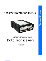
The HN-250 and HN-250X are NEMA 4X weatherproof versions of the
HopNet product line. The HN-254, which is an HN-250 with a 4 ft. cable, is
also available. The interface to the 250 and 250X allows the Host to
communicate with the Remote unit through an integrated 50 ft (15 meter)
cable. The HN-250 and 250X can act as either bases or remotes.
The HN-250 Remote has an internally mounted 6 dBi patch antenna. The
built-in antenna of the HN-250 case greatly eases outdoor installation since
no antenna feedline cable or adapters are needed. The 6 dBi antenna gain
increases the radiated EIRP to +30 dBm when the high power setting is
selected and the effective receiver sensitivity to –98 dBm. The HN-250X has
a TNC connector for attaching an external antenna and a mounting kit (part
no.: HN250X-MKIT) that accommodates both the HN-250X and any of the
following external antennas:
CORNER249
CORNER2414
OMNI249
OMNI2412
Operating Frequency
The HopNet family operates in the 2.4 GHz ISM band that allows for license-
free use and worldwide compliance.
HopNet Frequency Hopping Spread Spectrum Advantages
In the frequency domain, a multipath fade can be described as a frequency
selective notch that shifts in location and depth over time. Multipath fades
typically occupy five percent of the band. A conventional radio system
typically has a five percent chance of signal impairment at any given time due
to multipath fading.
Frequency Hopping Spread Spectrum reduces the vulnerability of a radio
system to interference from jammers and multipath fading by distributing or
spreading the signal over a larger region of the frequency band.
©2009-2015 by Murata Electronics N.A., Inc.
HN-210D/X, HN-214 D/X Rev. 2.0 01-16-15 Page 2 of 55 www.murata.com

The fade resistant, HopNet frequency-hopping technology employs up to 86
channels and switches channels over 100 times a second to achieve high
reliability throughput.
HopNet Data Integrity
An on-board 1 KB buffer and error correcting over-the-air protocol ensure
data integrity even in the presence of weak signals or jammers. The serial
interface handles both data and control of asynchronous data rates of up to
115 Kbps.
Flexible Power Management
The power can be set at 10mW, 100mW (default) or 250mW using the
included software. Reduced power can reduce the size of the coverage zone,
which may be desirable for multiple network indoor applications. You can also
place the transceiver module in a power-save mode, which enables smart
power management. Smart power management allows a remote unit to drop
into a lower current standby mode during transmission or receiving gaps.
This feature also allows Hopnet products to be used in various countries
where the output power requirements may vary due to regulation.
Advanced Features
HopNet modems have many advanced features:
• Employ frequency hopping technology with up to 86 channels in the
2401 to 2475 MHz frequency range
• Support digital addressing for up to 64 networks, with 62 remotes per
network.
• Use transparent ARQ protocol
• Use same hardware for all supported data rates
• Supports up to 115 Kbps asynchronous data rates
• Full Duplex operation
• Store setup configuration in nonvolatile memory (FLASH)
• Fast acquisition – less than 2 seconds is the typical time to acquire
hopping pattern
• Smart power management features
External Antenna
HN-250X Base/Remote Unit
Built-In Antenna
HN-250 Base/Remote Unit
©2009-2015 by Murata Electronics N.A., Inc.
HN-210D/X, HN-214 D/X Rev. 2.0 01-16-15 Page 3 of 55 www.murata.com


Getting Started
A pair of HN-250s is set up by performing the following steps:
• Install the HopNet Wizard configuration program on a PC
• Connect the HN-250 to the PC
• Set one HN-250 as a base radio
• Run a communications test
These steps are described in detail below. Other steps you may want to
perform include:
• Change the baud rate
• Change the radio network number
• Change how fast the radios change frequencies
Refer to the Configuring the Network section of this manual for details on
these steps.
Install the HopNet Configuration Wizard on a PC.
The HopNet Configuration Wizard is located on the software and
documentation CD included in the HN-250 package. Install the program by
inserting the CD in the PC and following the installation wizard. If Autorun has
been turned off, double-click on setup.exe on the CD to start the wizard.
Connect the HN-250 to the PC.
Connect the serial adapter box to a serial port on the PC using the serial
cable provided.
©2009-2015 by Murata Electronics N.A., Inc.
HN-210D/X, HN-214 D/X Rev. 2.0 01-16-15 Page 5 of 55 www.murata.com

Connect the end of the cable from the HN-250 (RJ45 connector) to the small
serial adapter box.
Connect power to the HN-250 by plugging one end of the wall-mount power
supply into the serial adapter box and the other end into a wall outlet. A green
LED on the serial adapter box will turn on indicating power is present.
Set one HN-250 to act as the base.
When using HN-250s, one unit, and only one, must be set as the base. All
other HN-250s must be set as remotes. With an HN-250 connected to the PC,
start the HopNet Configuration Wizard program by double-clicking on the icon
on the desktop. The HopNet Configuration Wizard will automatically detect
which serial port the HN-250 is connected to and the baud rate of the HN-
250. When the radio has been detected, the Continue button will appear.
Click on the Continue button to bring up the next screen.
©2009-2015 by Murata Electronics N.A., Inc.
HN-210D/X, HN-214 D/X Rev. 2.0 01-16-15 Page 6 of 55 www.murata.com

The program will read and display the current settings of the HN-250. The
HN-250 is shipped from the factory as a remote. The Remote button on the
Wizard screen will appear depressed indicating the HN-250 is a remote.
NOTE: The S/N displayed in the bottom left corner is the serial number
of the radio inside the unit and is different from the serial number of the
HopNet unit. Both the HopNet unit serial number and the radio serial
number are on the radio unit of the HopNet product.
To set the HopNet radio as a base, click on the Base button. The Base button
will depress and the Remote button will pop up. The screen heading will
change from “Remote Parameters” to “Base Parameters.”
©2009-2015 by Murata Electronics N.A., Inc.
HN-210D/X, HN-214 D/X Rev. 2.0 01-16-15 Page 7 of 55 www.murata.com

The Apply Settings button will appear at the bottom of the HopNet
Configuration Wizard screen. Click on the Apply Settings button to set the
HopNet radio as the base.
Run a communications test.
To run a communications test, connect one HopNet radio set as a base to
one PC running the Wizard and another HopNet radio set as a remote to
another PC running the Wizard. Verify that the Carrier Detect LED (CD) on
the radio is on (red), the fifth parameter box on the lower left of the window
will have DCD (as shown above right). Click on the Send Data button on the
HopNet Configuration Wizard screen on both PCs. The HopNet radio set up
as the base will send the message “This is a test message from the Base
radio.” to the remote HopNet radio. This message will be displayed in the
message window of the Wizard running on the remote PC. The remote
HopNet radio will send the message “This is a test message from the Remote
radio.” to the base HopNet radio. This message will be displayed in the
message window of the Wizard running on the base PC. The test will run
continuously until the Stop button is clicked.
NOTE: If your computer has two serial ports, both the base and the
remote HopNet radios can be connected to the same PC and the
communications test run by opening a second window running the
Wizard. Open the second window by simply double-clicking on the
Wizard icon on your desktop.
©2009-2015 by Murata Electronics N.A., Inc.
HN-210D/X, HN-214 D/X Rev. 2.0 01-16-15 Page 8 of 55 www.murata.com

The Serial Adapter Box
The HN-250 and HN-250X remotes interface with the user’s hardware
through a serial adapter box. The interface adapter supplies power and
signal to the remote unit. The interface to the remote unit is a standard RS-
232 DB-9 serial interface. To have all functions of the HN-250 available,
including configuration and hardware flow control, the eight signal lines must
be connected. The HN-250 serial connector is set up as a DCE device. This
allows communication with a PC using the straight through serial cable
provided with the HN-250. To connect the HN-250 to another DCE device, a
cross-over cable must be used. The connector pin-out is detailed in the figure
and table below.
©2009-2015 by Murata Electronics N.A., Inc.
HN-210D/X, HN-214 D/X Rev. 2.0 01-16-15 Page 9 of 55 www.murata.com

3 Wire Operation
If configuration and hardware flow control is not necessary, the HN-250 can
be used in 3-wire mode. In this mode, only Ground, Receive Data and
Transmit data are connected
Remote Pin-Out, RS-232
Pin
Number
Signal
Type
Description
1 DCD Output Data Carrier Detect. For remotes, DCD
indicates that the remote has successfully
acquired the hopping pattern.
2 RXD Output Output for received serial data.
3
TXD
Input
Input Serial Data to be transmitted
4 DTR Input Data Terminal Ready. Sleep/ wakes radio
transceiver.
5 GND - Signal and Chassis Ground
6 DSR Output Data Set Ready. Response to DTR.
7 RTS Input Request to Send. Gates the flow of receive
data from the radio to the user on or off. In
normal operation signal should be asserted.
8 CTS Output Clear to Send. Used to control transmit flow
from the user to the user to the radio. The
WIT 2410 radio module supports hardware
flow control only and does not support
software flow control (e.g. Xon-Xoff).
9 Not Used - Not Used
Note: When the HN-250 and HN-250X are used as three wire serial devices, DTR
and RTS do not have to be used.
RS-232 Interface
9 Not Used
8 Clear to Send (CTS)
7 Request to Send (RTS)
6 Data Set Ready (DSR)
5 Ground
4 Data Terminal Ready (DTR)
3 Transmit Data (TX)
2 Receive Data (RX)
1 Data Carrier Detect (DCD)
©2009-2015 by Murata Electronics N.A., Inc.
HN-210D/X, HN-214 D/X Rev. 2.0 01-16-15 Page 10 of 55 www.murata.com

Guidelines for Installation
When installing your system, always consider the following points:
Directional antennas are best for remote unit sites. They may increase the
cost, but they confine the transmission path to a narrow lobe and minimize
the interference from nearby stations.
For systems with constant interference present, you may need to change the
polarity of the antenna system and reduce data streams. Groups of short data
streams are more reliable and have a better chance of success in the
presence of interference than do long data streams.
Systems installed in rural areas are least likely to encounter urban
interference.
Multiple HopNet systems can operate in close proximity to each other but
require a unique network address.
Poor quality coaxial cables will seriously degrade system performance. Use
low- loss cable that is suitable for 2.4 GHz operation.
Short cable runs minimize signal loss.
Aiming the Antenna and Placing the Remote
Use the following guidelines for aiming the antenna and placing the Remote.
Do not place anything immediately in front of the antenna that could obstruct
its radiation pattern. Because the antenna in the HopNet Remote is inside the
unit, the antenna must have a clear line of sight.
Use the sticker on the HN-250 Remote unit to help you locate and aim the
antenna. The sticker indicates which direction the antenna is pointing.
Be sure the antenna end of the HN-250 Remote faces the Base or Repeater
that it is communicating with. Our tests have found that antenna placement is
not critical as long as the patch antenna is facing in the general direction of
the other end of the link.
If possible, place the Remote unit at a higher elevation than the structures
surrounding it to increase range and link reliability. Since the Remote will
operate with up to 100 feet of interconnect cable between it and the Host, you
can mount the unit on top of a building or other structure that will provide
higher elevation.
Interconnect Cable
The HN-250 and HN-250X come with 50’ (15 meters) of high quality
interconnect cable. The cable may be lengthened by adding an additional 50’
cable (part no.: CBLEXT50). The maximum cable length that the HN-250 and
HN-250x will support is 100’ (30 meters).
©2009-2015 by Murata Electronics N.A., Inc.
HN-210D/X, HN-214 D/X Rev. 2.0 01-16-15 Page 11 of 55 www.murata.com

Configuring the Network
You can configure the HopNet network using a PC and the HopNet
Configuration Wizard software provided by Murata, Inc. The Wizard runs
under Windows 95/98/NT/2000/XP. This chapter provides the information you
need to configure your network.
HopNet Configuration Wizard (5.0 or later)
If you haven’t already installed the Wizard program, refer to the Getting
Started section of this manual for instructions. Open the Wizard by double-
clicking on the icon on the desktop. When the Wizard boots up, it will
automatically detect the serial port to which the HopNet radio is connected
and its baud rate. This process takes a few seconds to complete. During this
process, the “Please wait” screen is displayed. Once the radio has been
found and the Baudrate determined, the “Finished” screen is displayed. Click
on the Continue button to enter the Wizard.
NOTE: The HopNet configuration Wizard is used with a variety of Murata
radios. Not all radios support all the functions and features of every
Murata radio. Thus, some selections in the Wizard will be grayed out if
they are not applicable to the radio in use.
After detecting the serial port and baud rate of the HopNet radio, the Wizard
reads the settings of the HopNet radio that is connected to the PC and will
display them in the various parameter windows. In the bottom left corner of
the Wizard window, the Base/Remote status, the serial number and the
communication port are always displayed.
©2009-2015 by Murata Electronics N.A., Inc.
HN-210D/X, HN-214 D/X Rev. 2.0 01-16-15 Page 12 of 55 www.murata.com

NOTE: The S/N displayed in the bottom left corner is the serial number
of the radio inside the unit and is different from the serial number of the
HopNet unit. Both the HopNet unit serial number and the radio serial
number are on the radio unit of the HopNet product. The Wizard will also
prompt to save the configuration settings to a file.
When a parameter value is changed from the value currently in the HopNet
radio, the parameter label and value will turn red and the Apply Settings
button will appear. When the value is changed back to the value that is
currently in the attached HopNet radio, the label and parameter value will
return back to black. When new values are applied to the HopNet radio, the
red values will turn black indicating the updated values in the radio.
NOTE:The changes are not sent to the HopNet radio until the Apply
Settings button is clicked.
Context sensitive help is available through the F1 key or Help menu.
©2009-2015 by Murata Electronics N.A., Inc.
HN-210D/X, HN-214 D/X Rev. 2.0 01-16-15 Page 13 of 55 www.murata.com

Parameters Tab
The Wizard program opens the main screen with the Parameters Tab
displayed. The parameters screen of the Wizard allows the following variables
to be set;
1. Base or Remote
2. Point-to-Point or Multipoint
3. Baud rate
4. Network number
5. Lockout Key
6. Roaming Mode
7. Protocol Mode
Depending on whether HopNet radio is configured as a Remote or Base
when first connected, the heading on the Parameters page will display either
“Remote Parameters” or “Base Parameters.” If the radio has a Modbus
adapter, Transparent, Modbus and DNP3 selections will appear above the
Point-Point-Multipoint selection as shown below.
©2009-2015 by Murata Electronics N.A., Inc.
HN-210D/X, HN-214 D/X Rev. 2.0 01-16-15 Page 14 of 55 www.murata.com

Network Number
This parameter is also known as Set Hopping and is the same command as
wn.(Refer to “Configuration Commands” section for additional information on
commands.) By using different network numbers or “hopping patterns”,
nearby or co-located networks can avoid interfering with each other’s
transmissions.
BaudRate
Also known as Set Data Rate Divisor (command sd) this parameter sets the
serial bit rate between the modem and the host.
Lockout Key
This parameter is the same as wl and allows further network segregation
beyond the network number. This feature allows multiple co-located networks
in which global roaming is enabled. By using different lockout keys, the bases
to which remotes link can be limited or segregated.
Roaming Mode
This parameter is the same as wg and allows remote radios to Roam or only
link to specific base stations.
©2009-2015 by Murata Electronics N.A., Inc.
HN-210D/X, HN-214 D/X Rev. 2.0 01-16-15 Page 15 of 55 www.murata.com
/