Page is loading ...


PMA AMPLIFIER SERIES
2
CONTENTS
IMPORTANT SAFETY INSTRUCTIONS 4
WELCOME 5
MODEL NUMBERS 5
POWER APPLICATIONS 5
RACK MOUNTING 6
HARDWARE FEATURES: 7
FRONT PANEL 7
1 - LCD DISPLAY 7
2 - POWER LED 9
REAR PANEL 10
1 - POWER AND STATUS AREA 11
2 - PROGRAMMING AND CONTORL AREA 12
3 - INPUT/OUTPUT AREA 13
SOFTWARE FEATURES 15
PMA MANAGER MAIN SCREEN 16
1 - TITLE BAR 16
2 - MAIN MENU 17
3 - INFORMATION PANE 18
4 - DSP CONTROL PANEL 19
5 - UPDATE AMPLIFIER MEMORY BUTTON 22
6 - STATUS BAR 22
COMPENSATION FILTERS 23
SCREEN COMPENSATION 23
CLOTH COMPENSATION 24
ROOM BOUNDARY COMPENSATION 24
HIGH AND LOW PASS FILTERS 26
AMPLIFIER HOOKUP EXAMPLES 27
TWO-WAY BI-AMP “CENTER CHANNEL” HOOKUP EXAMPLE 27
THREE-WAY TRI-AMP “CENTER CHANNEL” HOOKUP EXAMPLE 28
DUAL SUB / BI-AMP CENTER CHANNEL HOOKUP EXAMPLE 28

PMA AMPLIFIER SERIES
3
AMPLIFIER PROGRAMMING 29
PROGRAMMING OVERVIEW 29
CONCEPTS TO KNOW 30
PROGRAMMING STEPS 32
STEP 1 : MAKE A PLAN 32
STEP 2 : CONNECT AMPLIFIER TO COMPUTER 32
STEP 3 : POWER ON AMPLIFIER 32
STEP 4 : RUN PMA MANAGER SOFTWARE 33
STEP 5 : SET DSP PARAMETERS FOR EACH AMPLIFER CHANNEL 34
STEP 6 : STORE DSP PARAMETERS IN AMPLIFIER MEMORY 36
TROUBLESHOOTING 37
SPECIFICATIONS 40
WARRANTY 41
Professional Home Cinema, LLC 3-Year Limited Warranty 41
CONTACTING PROFESSIONAL HOME CINEMA, LLC 41

PMA AMPLIFIER SERIES
4
IMPORTANT SAFETY INSTRUCTIONS
1. Read all instructions.
2. Keep these instructions.
3. Heed all warnings.
4. Follow all instructions.
5. Do not use this apparatus near water.
6. To prevent re or shock, do not expose this equipment to moisture or water.
7. Clean only with a dry cloth.
8. Do not block any ventilation openings. Install in accordance with manufacturer’s instructions.
9. Do not install near any heat sources such as radiators, heat registers, stoves or other apparatus (including other rack
equipment) that produce heat.
10. Do not defeat the safety purpose of the grounding -type plug. A grounding plug has two blades and a grounding
prong. The wide blade and third prong are provided for your safety. If the provided plug does not t your outlet, con-
sult an electrician for the replacement of the obsolete outlet.
11. Protect power cord from being walked on or pinched, particularly at plugs, convenience receptacles, and point where
they exit the apparatus.
12. Use only attachements/accessories specied by Professional Home Cinema, LLC.
13. Use only with hardware, brackets, stands, and components sold with the apparatus or supplied by Professional Home
Cinema, LLC
14. Unplug the apparatus during lightning storms or when unused for long periods of time.
15. Refer all servicing to qualied service personel. Servicing is required when the apparatus is damaged in any way, such
as power supply cord or plug is damaged, liquid has been spilled or objects have fallen into the apparatus, the appara-
tus has been exposed to rain or moisture, does not operate normally or has been dropped.
16. To completely disconnect this apparatus from the AC Mains, disconnect the power supply cord from the AC receptacle.
17. The mains plug of the power supply cord shall remain readily operable.
!
The lightning ash with arrowhead symbol with equilateral triangle
is intended to alert the user to the presence of uninsulated “danger-
ous voltage” within the product’s enclosure that may be of sucient
magnitude to constitute a risk of electric shock to persons.
The exclamation point within an equilateral triangle is intended to
alert the user to the presence of important operating and mainte-
nance (servicing) instructions in the literature accompanying the
product.
CAUTION: TO REDUCE THE RISK ELECTRIC SHOCK, DO NOT REMOVE
THE COVER, NO USER-SERVICEABLE PARTS INSIDE. REFER SERVIC-
ING TO QUALIFIED PERSONEL.
WARNING: TO PREVENT FIRE OR ELECTIC SHOCK, DO NOT EXPOSE
EQUIPMENT TO RAIN OR MOISTURE.
© COPTYRIGHT 2011, PROFESSIONAL HOME CINEMA., LLC

PMA AMPLIFIER SERIES
5
WELCOME
The PMA series ampliers represent the second generation ampliers from Pro Audio Technology
and were developed with a single primary goal: to make installing, conguring and optimizing your
PRO audio system straight forward and as painless as possible.
MODEL NUMBERS
The model number of your PMA amplier designates the installed amplier power. The numeral
in the rst (left-most) position indicate the power in Channel 1, the second numeral indicates the
power installed in Channel 2, and so on.
Model numerals:
'2' = 200W
'4' = 450W
'9' = 1000W
'0' = No power installed
Model number sux:
'T' = Indicates optional input transformers are installed
Example: PMA-9942T has 1000W installed in Channels 1 and 2, 450W installed in Channel 3 and
200W installed in Channel 4 and has optional input isolation transformers installed.
POWER APPLICATIONS
As a general rule, each of the three power levels is intended to drive certain loudspeaker drivers or
systems within the home cinema or distributed audio application.
Bi or Tri-Amplied Large Format Full Range Systems (i.e. SCR-2215sm):
LF Driver : 450W or 1000W
MF Driver : 450W
HF Driver : 450W
Bi-Amplied Medium Format Full Range Systems (i.e. SCR-12sm):
LF Driver(s) : 450W
HF Driver : 200W
Passive or Bi-Amp Small Format and Architectural Full Range Systems (i.e. iw models):
Bi-amp LF Driver : 200W
Bi-amp HF Driver : 200W
Passive Mode : 200W
Subwoofers:
Small Format Architectural Subwoofers : 200W
Medium Format Subwoofers : 450W
Large Format Subwoofers : 1000W

PMA AMPLIFIER SERIES
6
RACK MOUNTING
The PMA series ampliers ship from the factory with rack mount ears installed and are ready to be
placed into any industry-standard 19” equipment rack. The PMA chassis is 2U high.
To keep the equipment and listening rooms as quiet as possible, the PMA ampliers do not have
cooling fans and therefore rely on convection to remove waste heat from the chassis. The good
news is, however, that the PMA ampliers are extremely ecient (> 80% eciency). Still, with EIGHT
HUNDRED to FOUR THOUSAND WATTS per chassis, even with 80% eciency they do generate a
modest amount of heat, especially at idle. (Refer to the SPECIFICATIONS section for more informa-
tion).
For this reason, it is recommended that you place a 1U spacer between the PMA amplier chassis
and any neighboring equipment, including other PMA ampliers, to insure adequate ventilation.
During normal operation, the front panels of the PMA ampliers will become warm to the touch, but
will not become hot.
To further minimize heat generated at idle, it is recommended that you take advantage of the
STANDBY feature of the amplier, and place the amps into STANDBY whenever not in use. This will
keep power consumption and therefore waste heat to a minimum.
PMA AMPLIFIERS WITH 1U RACK SPACER
RACK MOUNTING
PLACE A 1U SPACER BETWEEN AMPLIFIERS AND
OTHER COMPONENTS IN THE RACK

PMA AMPLIFIER SERIES
7
FRONT PANEL
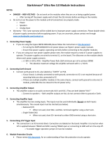
1 - LCD DISPLAY
The display will illuminate and text will appear when the amplier main power is turned on. At start
up, the display will temporarily display the amp model and serial number along with rmware ver-
sion currently installed in the amplier. Once the amplier has completed its initialization process,
the display will show details about the amplier conguration and programming.
The text on each row of the display corresponds to an amplier channel. The top row, Row 1, corre-
sponds to Channel 1 of the amplier. All data shown on this row applies only to Channel 1. Rows 2
through 4 correspond to Channels 2 through 4, respectively.
Each column of the LCD display indicates an important parameter of the amplier status and/or am-
plier programming. Column headings have intentionally been omitted from the chassis front panel
to preserve a clean appearance. Please review the descriptions below to learn what information is
shown in each column. After reviewing the information, deciphering the displayed text will be easy
and intuitive.
When the amp is placed into STANDBY mode, the display backlight will dim but the text will still be
visible.
HARDWARE FEATURES:
HARDWARE FEATURES - FRONT PANEL
PMA FRONT PANEL
1 - LCD DISPLAY
2 - POWER LED

PMA AMPLIFIER SERIES
8
1.1 - INSTALLED POWER
The rst display column indicates the installed amplier power in Watts into 4-ohms. Most PRO
LF drivers are 4-ohm nominal impedance, so this number is an accurate description of power
available. If no power module is installed, this column will read “NONE”.
1.2 - CHANNEL MODIFIED INDICATORS
When a DSP setting has been modifed on a amplier channel but the changes have not yet been
saved to amplier memory, an aesterisk will appear on each side of the Signal Routing column.
Once the current settings have been saved to amplifer memory, the asterisks will disappear. No
asterisks on the front panel display indicates that settings in amp memory are “in-sync” with the
running DSP programming.
1.3 - SIGNAL ROUTING
The second display column indicates the source currently routed to the amplier channel (as set
up in PMA Manager control software, see “Amplier Programming”). The source may be any one
of the four balanced audio input jacks on the amplier back panel, or the channel may be routed
to the internal pink noise generator. If the channel is routed to the internal pink noise generator,
this column will read “NOISE”.
If the channel is currently muted via software control, this column will show “MUTE”. From the
factory, each channel is by default routed to its corresponding balanced audio input jack. That is,
Channel 1 of the amplier is “listening” to Channel 1 balanced audio input. Channel 2 is routed to
the Channel 2 balanced audio input, and so on. Signal routing can easily be changed as required
by the system design via PMA Manger control software.
HARDWARE FEATURES - FRONT PANEL
LCD DISPLAY
1.1 - INSTALLED POWER
1.3 - SIGNAL ROUTING
1.4 - SPEAKER PROGRAM
1.5 - COMPENSATION
FILTER
CHANNEL 1
CHANNEL 2
CHANNEL 3
CHANNEL 4
1.2 - CHANNEL MODIFIED
INDICATORS 1.6 - CHANNEL GAIN

PMA AMPLIFIER SERIES
9
1.4 - SPEAKER PROGRAM
Column three of the display indicates the speaker program that is installed (as set up in PMA
Manager control software, see “Amplier Programming”) for the channel. From the factory, the
amplier is pre-programmed with no speaker program and this column will display “NONE”.
1.5 - COMPENSATION FILTER
The forth column indicates any acoustic compesation lter installed (as set up in PMA Manager
control software, see “Amplier Programming”) for the channel. These customized lters are used
to correct for the acoustic eect of perforated video screens, nearby room boundaries or to apply
high or low pass ltering. From the factory, the amplier is pre-programmed with no compensa-
tion lter installed and this column will read “NONE”.
1.6 - CHANNEL GAIN ADJUSTMENT
The fth column indicates the channel gain setting (as set up in PMA Manager control software,
see “Amplier Programming”). Channel gain should only be used in certain circumstances such
as adjusting mulitple subwoofer levels when the preamp processor in the system has only a
single LFE output. From the factory, all channel gains are set to 0.0dB
CAUTION:
All PRO loudspeaker programs have precisely optimized output level that precisely match
the outputs of the drivers within a multi-way speaker system. NEVER ADJUST THE LEVELS
OF INDIVIDUAL DRIVERS WITHIN A MULTI-WAY LOUDSPEAKER SYSTEM RELATIVE TO ONE
ANOTHER.
.
2 - POWER LED
This LED will illuminate when the amplier main power is ON and the amp is not in Standby Mode.
When the amp is OFF, in STANDBY MODE or PROTECT MODE, this LED will be o.
HARDWARE FEATURES - FRONT PANEL

PMA AMPLIFIER SERIES
POWER
STANDBY/PROTECT
ON
WARNING: SHOCK HAZARD . DO NOT OPEN. NO USER-SERVICEABLE PARTS INSIDED ESIGNED AND ASSEMBLED IN HUNTINGT ON BEA CH, CA BY PRO AUDIO TECHNOLOGY
DSP ACTIVITY
PROGRAM
TRIGGER
USB
ALL INSTALLED CHANNELS MUST BE
PROGRAMMED WITH CORRE CT
LOUDSPEAKER PROGRAM BEFORE
OPERATION. FAILURE TO DO SO WILL
RESULT IN LOUDSPEAKER DAMAGE.
PRO AUDIO TECHNOLOGY “PMA
MANAGER” SOFTWARE REQUIED.
-+
INPUT LOOP
-+
SHORT OR 0V:
OPEN OR +12 V:
STANDBY
OPERATE
!
CHANNEL 1
LOOPINPUT OUTPU T
+
-
CHANNEL 2
+
-
SIGNAL
CLIP
PROGRAM
LOOPINPUT OUTPU T
CHANNEL 3
LOOPINPUT OUTPU T
+
-
CHANNEL 4
+
-
LOOPINPUT OUTPU T
ON
DISPLAY BACKLIGHT
SIGNAL
CLIP
PROGRAM
SIGNAL
CLIP
PROGRAM
SIGNAL
CLIP
PROGRAM
WARNING:
10
PMA REAR PANEL
HARDWARE FEATURES - REAR PANEL
1 - POWER AND STATUS INDICATORS 3 - INPUTS AND OUTPUTS
2 - PROGRAMMING AND CONTROL
REAR PANEL
With the expception of the Power LED and LCD display, all other features of the PMA amplers can be
found on the amp rear panel. The layout of the connectors and controls have been carefully designed
to make connecting to and operating the amplier as easy as possible.
In addition to the usual input and output connectors, you will nd a host of LED’s that indicate amp
operation and programming status which oer useful feedback during system setup and debugging.
There are also labels indicating installed power and speaker program for each channel.
To make installation and setup as easy as possible, all information that is available on the front panel
(and in PMA Manager conrtol software), can also be found here.
The panel is divided into three main areas: POWER AND AMP STATUS, PROGRAMMING AND CONTROL
and INPUTS AND OUTPUTS.
We’ll now take a look at the features within each area individually.

PMA AMPLIFIER SERIES
POWER
STANDBY/PROTECT
ON
WARNING: SHOCK HAZARD . DO NOT OPEN. NO USER-SERVICEABLE
DSP ACTIVITY
PROGRAM
TRIGGER
USB
ALL INSTALLED CHANNELS MUST BE
PROGRAMMED WITH CORRECT
LOUDSPEAKER PROGRAM BEFORE
OPERATION. FAILURE TO DO SO WILL
RESULT IN LOUDSPEAKER DAMAGE.
PRO AUDIO TECHNOLOGY “PMA
MANAGER” SOFTWARE REQUIED.
-+
INPUT LOOP
-+
SHORT OR 0V:
OPEN OR +12V:
STANDBY
OPERATE
!
CHANNEL
LOOPINPUT
CHANNEL
SIGNAL
CLIP
PROGRAM
LOOPINPUT
ON
DISPLAY BACKLIGHT
SIGNAL
CLIP
PROGRAM
WARNING:
11
HARDWARE FEATURES - REAR PANEL
POWER AND STATUS AREA
1 - POWER AND STATUS AREA
1.1 - MAIN POWER SWITCH
Press the top of the rocker switch to engage the amplifer main electrical power. Press the bottom
of the rocker switch to disengage the power and turn the amplier o. If using 12VDC or relay
trigger to control amp operation, this switch should be left in the ON position.
1.2 - AMPLIFIER STATUS INDICATORS
DSP ACTIVITY - This LED will illuminate, solid or blinking, when communicating with the ampli-
er via USB software control.
STANDBY/PROTECT - This LED will illuminate when the amp has been put into standby condi-
tion, or when the amp has entered protection mode due to an operational fault.
POWER - This LED will illuminate when the amplier main power is on.
1.3 - FRONT PANEL DISPLAY BACKLIGHT DEFEAT
Use this switch to defeat (turn-o) the amplier front panel LCD display backlight. It is recom-
mended that once installation is complete, the front panel backlight be turned o with this
switch to conserve power and preserve backlight life. This will defeat the backlight itself, but not
the text displayed. STANDBY and PROTECT modes will still be indicated on the front panel via the
power LED.
1.4 - AC INLET
Main AC power inlet. Connect the mains power cable here.
CAUTION: CONNECT ONLY LINE VOLTAGE INDICATED ON SERIAL NUMBER LABEL. CON-
NECTING THE AMPLIFIER TO ANY OTHER AC VOLTAGE WILL RESULT IN AMPLIFIER DAMAGE.
WARNING: THIS AMPLIFIER MUST BE CONNECTED TO AN AC OUTLET WITH PROTECTIVE
EARTHING CONNECTION
1.1- MAIN POWER
SWITCH 1.3 - DISPLAY BACKLIGHT
DEFEAT
1.2 - STATUS INDICATORS
1.5 - SERIAL NUMBER LABEL
1.4 - AC INLET

PMA AMPLIFIER SERIES
12
HARDWARE FEATURES - REAR PANEL
1.5 - AMPLIFIER SERIAL NUMBER LABEL
This label indicates amplier model, serial number and operating voltage.
POWER
STANDBY/PROTECT
ON
WARNING: SHOCK HAZARD . DO NOT OPEN. NO USER-SERVICEABLE PARTS INSIDED
DSP ACTIVITY
PROGRAM
TRIGGER
USB
ALL INSTALLED CHANNELS MUST BE
PROGRAMMED WITH CORRECT
LOUDSPEAKER PROGRAM BEFORE
OPERATION. FAILURE TO DO SO WILL
RESULT IN LOUDSPEAKER DAMAGE.
PRO AUDIO TECHNOLOGY “PMA
MANAGER” SOFTWARE REQUIED.
-+
INPUT LOOP
-+
SHORT OR 0V:
OPEN OR +12V:
STANDBY
OPERATE
!
CHANNEL 1
LOOPINPUT OUTPU T
+
-
CHANNEL 2
+
-
SIGNAL
CLIP
PROGRAM
LOOPINPUT OUTPU T
ON
DISPLAY BACKLIGHT
SIGNAL
CLIP
PROGRAM
WARNING:
PROGRAMMING AND CONTROL AREA
2.1 - USB PORT
2.3 - TRIGGER LOOP OUTPUT
2.2 - TRIGGER INPUT
2 - PROGRAMMING AND CONTORL AREA
2.1 - USB PORT
Connect the PMA amplier to your computer at this port using a mini USB cable. Microsoft Win-
dows XP or Windows 7 will discover the PMA unit and install the required drivers. When doing
this for the rst time, this process may take a few minutes. On subsequent connections, Windows
will install the driver more quickly. Refer to “Amplifer Programming” section of this manual for
more information. Operating systems other than Windows XP and Windows 7 are not supported.
2.2 - 12V/CONTACT CLOSURE TRIGGER INPUT
Connect a 12VDC trigger output, or contact closure relay to this port using the supplied Phoenix
two-position male connector. The STANDBY/OPERATE TRIGGER will operate with applied DC volt-
age or with an open/short ciruit.
When connecting to a control system relay/contact closure output, program the relay to close
(short) the terminals to engage STANDBY; open the terminals for OPERATE. When connecting to
a DC trigger output, make sure to observe correct voltage polarity. Failure to do so could result in
damage to the PMA input or your component trigger output. 0VDC will engage STANDBY mode;
5VDC up to 12VDC will cause the amp come to out of STANDBY MODE and OPERATE.
3 - 12V/CONTACT CLOSURE LOOPING OUTPUT
Use this port to “loop” the Trigger input signal to another PMA chassis using the supplied Phoe-
nix two-position male connector. When using a DC trigger input, make sure to observe correct
polarity, or component damage may occur.

PMA AMPLIFIER SERIES
POWER
STANDBY/PROTECT
WARNING: SHOCK HAZARD . DO NOT OPEN. NO USER-SERVICEABLE PARTS INSIDED ESIGNED AND ASSEMBLED IN HUNTINGT
DSP ACTIVITY
PROGRAM
TRIGGER
USB
ALL INSTALLED CHANNELS MUST BE
PROGRAMMED WITH CORRECT
LOUDSPEAKER PROGRAM BEFORE
OPERATION. FAILURE TO DO SO WILL
RESULT IN LOUDSPEAKER DAMAGE.
PRO AUDIO TECHNOLOGY “PMA
MANAGER” SOFTWARE REQUIED.
-+
INPUT LOOP
-+
SHORT OR 0V:
OPEN OR +12V:
STANDBY
OPERATE
!
CHANNEL 1
LOOPINPUT OUTPU T
+
-
CHANNEL 2
+
-
SIGNAL
CLIP
PROGRAM
LOOPINPUT OUTPU T
CHANNEL
LOOPINPUT
CHANNEL
LOOPINPUT
ON
DISPLAY BACKLIGHT
SIGNAL
CLIP
PROGRAM
SIGNAL
CLIP
PROGRA
SIGNAL
CLIP
PROGRA
WARNING:
13
HARDWARE FEATURES - REAR PANEL
INPUT/OUTPUT AREA
3.1 - BALANCED ANALOG
AUDIO INPUT
3.3 - CHANNEL STATUS INDICATORS
3.6 - SPEAKER OUTPUTS
3.4 - CHANNEL POWER LABEL
3.2 - LOOPING OUTPUT
3.5 - PROGRAM LABEL LOCATION
3 - INPUT/OUTPUT AREA
3.1 - BALANCED ANALOG AUDIO XLR INPUT
Connect this balanced analog audio input to the post-processed analog audio output from your
surround sound processor. Pin 1 is ground; Pin 2 is signal +; Pin 3 is signal -. To minimize the risk
of unwanted ground plane noise, use of a balanced preamplifer is highly recommended.
When connecting to unbalanced (single-ended) audio outputs, connect pins 1 (GND) and 3(-) to-
gether and then to audio GROUND inside the male XLR jack at the amplier-end of the intercon-
nect cable. Make sure the preamp/processor is grounded. That is, make sure that it has a three-
prong grounding AC power cord. If it does not, you will need to connect the preamp chassis to
ground manually. Failure to connect to a properly grounded single-ended processor will likely result
in unwanted ground noise that will enter the system and be heard from the loudspeakers.
3.2 - BALANCED ANALOG AUDIO LOOPING OUTPUT
Use this XLR output to “loop” the analog audio input signal to another PMA chassis. This is useful,
for instance, when there are more than 4 subwoofers within a system and it’s necessary to route
the LFE signal to more than one PMA amplier.
NOTE: Signal input into one of the XLR balanced audio inputs may be routed to any amplier
channel within the same PMA amp via PMA Manager software (refer to “Amplifer Programming”
section of this manual for more information).

PMA AMPLIFIER SERIES
14
!
3.3 CHANNEL STATUS INDICATORS
PROGRAM (RED)
This LED will illuminate when a valid PRO loudspeaker program has been installed into the
PMA DSP for this channel. If this LED is not illuminated, that means no program is installed
and audio will not pass on this channel.
By default, the PMA amplifer is shipped from the factory with no program installed to prevent
“accidents” during system setup that may cause damage to the loudspeakers in the system.
Every channel of the amplifer must be correctly programmed via PMA MANAGER SOFTWARE
prior to amplier use.
CLIP (YELLOW)
This LED will illuminate when the amplier output maximum has been reached and the built-
in clip limiter is engaged. The limiter will prevent clipping from occuring.
SIGNAL (GREEN)
This LED will illuminate when a moderate input signal is detected at the input and will there-
fore “blink” in accordance with the strength of the audio content. Under high level signals,
the LED may illuminate constant.
3.4 - CHANNEL POWER LABEL
This label indicates the installed power on this channel and is placed at the factory.
3.5 - CHANNEL PROGRAM LABEL LOCATION
This outlined rectangular area will accept the blank labels provided with the PMA amplifer and
allow you to mark on the amp what program is installed in the channel. Use a perment maker
(i.e. Sharpie) to write the program on the label and ax it at this location. Alternately, use a label
maker to create your own program labels and ax them here.
3.6 - LOUDSPEAKER OUTPUTS
Connect a PRO passive loudspeaker system or bi or tri-amp speaker driver to these binding posts
making sure to observe correct polarity. The posts will accept bare wire or dual banana plugs.
High quality banana plugs are recommended for ease of installation and system maintenance.
CAUTION: THE AMPLIFIER MODULES INSIDE THE PMA AMPLIFIER OPERATE IN BRIDGED
(“BRIDGED TIED LOAD”, OR “BTL”) MODE. AS SUCH, BOTH LOUDPSPEAKER OUTPUT POSTS
ARE CONNECTED TO HOT SIGNALS. DO NOT CONNECT ANY SPEAKER OUTPUT POST TO
GROUND, OR AMPLIFIER DAMAGE WILL RESULT.
All connectors and indicators for each of channels 2 thru 4 follow the same layout.
HARDWARE FEATURES - REAR PANEL


PMA AMPLIFIER SERIES
16
PMA MANAGER MAIN SCREEN
SOFTWARE FEATURES
PMA MANAGER TITLE BAR
1 - TITLE BAR
In the top-most section of the user interface, known as the “Title Bar”, PMA Manager will display
information about the software and the connection to the amplier hardware.
1.1 PMA MANAGER SOFTWARE VERSION NUMBER
PMA Manager will display the running version of the softare showing the version, revision and
build code. Information about the software can also be found by selecting HELP -> ABOUT from
the main menu.
1.2 CONNECTION STATUS
If a valid connection to a PMA amplier exists, PMA Manager will show “[Connected]” immediate-
ly after the software version; if PMA Manager could not establish communication with an ampli-
er, it will display “[Disconnected]” here. If you’re having trouble establishing a connection, refer
to the TROUBLESHOOTING section of this manual.
PMA MANAGER MAIN MENU
1.1 - PMA SOFTWARE VERSION NUMBER
1.2 - CONNECTION STATUS

PMA AMPLIFIER SERIES
17
SOFTWARE FEATURES
2 - MAIN MENU
2.1 - FILE
The le menu contains menu commands related to amplier connections and le manage-
ment.
2.1.1 Connect
Select this menu item to connect to a new PMA amplier while the software is running
but is not connected to an amplier. A list of available ampliers will appear.
2.1.2 Disconnect
Select this menu item to disconnect from a PMA amplier, for example, when pro-
gramming a rack full of amps in order to move to the next unprogrammed amp.
2.1.3 Backup
Select Backup to store an archive of all current amp settings to a le on your local hard
disk that can later be recalled. This is useful when you use the same conguration on
many ampliers - you don’t need to manually enter all programs and settings, you can
simply restore the amp “image” from the backup le. This is also useful as a way to
keep record of settings should an amplier need to be replaced in the future.
2.1.4 Restore
Choose Restore to load all amplier settings from a previously made Backup le locat-
ed on your hard disk. This command will display all control settings in PMA Manager,
load them into the DSP, and store them in amplier memory.
2.1.5 Exit
Select Exit to disconnect from the PMA amplier and close PMA Manager Sotware.
2.2 - SETTINGS
The Settings menu contains commands related to software features and layout of the GUI.
2.2.1 - Enable Advanced Controls
Select Enable Advanced Controls to gain access to advanced DSP controls such as
channel level adjustment and low frequency paramtric EQ lters.
2.2.2 - View Command Window
Selecting this option will expand the software GUI to display a scrolling list of recent
commands executed by the software. PRO technical support engineers use this fea-
ture to decipher the operation of the software should a problem be encountered. It is
not needed during normal use.

PMA AMPLIFIER SERIES
18
3 - INFORMATION PANE
The Information Pane displays information about the currently-connected PMA Amplier hardware.
3.1 - PMA Amplier Model
3.2 - PMA Amplier Serial Number
3.3 - PMA Amplier Firware Version
3.4 - PMA Amplier Firmware Date
PMA MANAGER INFORMATION PANE
SOFTWARE FEATURES
2.3 - HELP
The Help menu contains commands related to user help and information.
2.3.1 User Manual
Selecting this option will load and display this manual in PDF format on your computer
screen for reference while running the software.
2.3.2 Technical Support
Brings up a form with information about how contact PRO Technical Support engineers.
2.3.3 About
Will display information about PMA Manager software.
3.1 - PMA AMPLIFIER MODEL
3.2 - PMA AMPLIFIER SERIAL NUMBER
3.3 - AMPLIFIER FIRMWARE VERSION
3.4 - AMPLIFIER FIRMWARE DATE

PMA AMPLIFIER SERIES
19
4 - DSP CONTROL PANEL
The DSP Control Panel is where you will interface with the software to load speaker programs, make
adjustments and route signals during setup and debugging. There is a row of software controls for
each channel. Think of the audio signal as owing from left to right along each row; you will be ad-
justing the processing parameters using the controls found along this path.
4.1 - Channel Designator
Indicates amp channel number, which corresponds to the inputs/output channel numbers on
the back of the amp.
4.2 - Installed Amplifer Power
Indicates the power in watts installed for each channel.
4.3 - Pink Noise On/O Button
Turns the internal pink noise generator on and o. Left-click button once to turn noise on; click
again to turn noise o. When on, the button will appear depressed and the text will turn blue.
When o, button text is white.
PMA MANAGER DSP CONTROL PANEL
SOFTWARE FEATURES
4.5 - ROUTING DROP DOWN LIST CONTROL
4.6 - SPEAKER PROGRAM DROP
DOWN LIST CONTROL
4.4 - MUTE ON/OFF BUTTONS
4.3 - PINK NOISE
ON/OFF BUTTON
4.1 - CHANNEL DESIGNATOR
4.2 - INSTALLED POWER 4.7 - COMPENSATION FILTER DROP
DOWN LIST CONTROL

PMA AMPLIFIER SERIES
20
4.4 - Mute On/O Buttons
Mutes the selected channel. Left-click the button once to engage mute; left-click again to un-
mute. When muted, the button will appear depressed and the text will turn blue. When un-mut-
ed, button text is white.
4.5 - Channel Routing Drop Down List Controls
This drop-down list control allows amp channels to be routed to any one of ve possible “sourc-
es”: Channels 1-4 analog audio XLR inputs (on amplier rear panel), or to the inernal pink noise
generator.
To select a source, left-click on the down arrow at the right edge of the control and a list of these
sources will appear. To select a souce from the list, left-click on the source name. The input
signal for that channel will then be routed to the source selected and the name of the source will
appear in the drop-down control.
4.6 - Channel Loudspeaker Program Drop Down List Controls
This drop down list control allows you to install the loudspeaker-specic DSP programs required
to operate all Pro Audio Technology loudspeaker systems. This includes both multi-amp (bi and
tri-amp) as well as passive crossover models.
To load a loudspeaker program, left-click on the down arrow at the right edge of the control and
a list of all available programs will appear. To select a program from the list, left-click on the pro-
gram name, which will include the loudspeaker model number and inidicate if the program is for
the woofer (“LF”), midrange (“MF”), tweeter (“HF”) or for a passive model (“-P”). The loudspeaker
program will then be loaded into the DSP chip for that channel and the name of the program will
appear in the drop-down control. Subwoofer programs will simply show the subwoofer name.
4.7 - Channel Compensation Filter Drop Down List Controls
This drop down list control allows you to install specially-designed lters to compensate for the
acoustic eect of listening room materials and loudspeaker positons. There are also high and
low pass lters for combining subwoofers and satellite speakers in distributed audio applications.
Please refer to “COMPENSATION FILTERS” section of this manual for more information.
To load a compensation lter, left-click on the down arrow at the right edge of the control and
a list of all available lters will appear. To select a lter from the list, left-click on the lter name,
which will be a description of the lters function (i.e. “80Hz High Pass”), describe a speaker posi-
tion (i.e. “2-surfaces”) or will be the model of a commercially available perforated video screen
or acoustic cloth (i.e. “Stuart Microperf”). The lter will then be loaded into the DSP chip for that
channel and the name of the lter will appear in the drop-down control.
SOFTWARE FEATURES
/