Page is loading ...

Ceramic Infrared Heaters
The following information should be considered when installing
ceramic infrared heaters.
Installation must be carried out by a competent person in
accordance with the current edition of the IEE Wiring Regulations
(BS 7671: Requirements for Electrical Installations) and any
applicable statutory regulations.
The heater should be preceded by a double pole isolating switch
preferably with an indicator light.
• The heaters should always be installed using the mounting
brackets provided to ensure adequate clearance from the
wall.
• Do not touch the heater while it is operating, the surfaces are
hot!
• Do not cover the heater, point it a flammable objects, or place
items closer than the stated safety distance as this result in a
risk of fire
• Heaters should not be installed in areas where hazardous
vapours may be present as defined in BS5345
• It is recommended the heaters are operated with the element
guard in place. The safety guards are only intended to
prevent large objects from directly hitting the ceramic emitters.
Some applications will necessitate additional precautionary
measures.
• A build up of moisture in the emitter can cause earth leakage
currents to flow, causing RCD’s to trip. Operating the heater
for a few minutes with the RCD removed will expel the
moisture and cure the problem. Where heaters with ceramic
emitter are installed in damp or wet areas they should be
used regularly to stop moisture building up in the emitters.
• Where RCD protection is used the heaters should be installed
over several circuits, each with its own protective device.
• The heater should only be installed in an indoor or weather
protected environment.

W. Tombling Ltd
Ceramic Infrared
Wall Mounted Heater
W. Tombling Ltd
Wembley House
Dozens Bank
West Pinchbeck
Spalding
Lincolnshire
PE11 3ND
Tel +44 (0) 1775 640049
Fax +44 (0) 1775 640050
www.tombling.com
mail@tombling.com
THESE INSTRUCTIONS SHOULD BE READ BEFORE
INSTALLATION AND RETAINED BY THE USER FOR
LATER REFERENCE

Before installing this heater, please read all the enclosed instructions carefully and
follow any recommendations regarding installation and use.
Electrical installation
The HC range comprises 1, 2 and 3 ceramic element models:
• One and two ceramic single phase 230V heaters are factory fitted with high
temperature silicon rubber flexible cable conforming to BS 6500 having a
temperature rating of 180°C continuous (H05SS-F).
• Three ceramic heater models are supplied without cables, and configured for
single phase 230V operation. They can be converted to 3 phase and neutral 400V
by removing the two red wires under the right hand cover. For connection use only
silicon rubber flexible cable conforming to BS 6500 having a temperature rating of
180°C (H05SS-F).
• The heaters must be earthed.
• To prevent nuisance tripping use type C MCBs. In multi-heater installations spread
the heaters over several circuits.
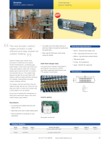
The heater is supplied with a wall mounting bracket ready for attachment to the
heater. Place the heater face down and attach one 'U' bracket to back. Make sure
cable gland is towards the bottom of the heater
movement
Location
• Heaters should be angled at 30° to 45° from the vertical, and never straight down.
• There must always be a minimum clearance of 450mm between the top of the
heater and the ceiling.
Wall mounting
• Decide whether vertical movement only (Diagram A) or vertical/horizontal
movement (Diagram B) is required for correct positioning of heaters and assemble
as shown.
• Avoid mounting heaters on structures liable to vibrate.
• Recommended mounting heights and safety distances should always be
observed.

Commissioning
• Perform Insulation and Earth Continuity Tests.
• Switch on the heater(s) and confirm that the ceramic elements are operating.
• Ensure each heater aims its warmth into the target area by adjusting the heater
angle(s) as necessary, then tighten the bracket bolts when satisfactory coverage is
achieved.
• The user/customer should be made aware of all aspects of operation and safety
and is strongly advised to retain these instructions for future reference.
• In unoccupied premises it is recommended the heating system is switched off and
isolated from the electrical supply.
Maintenance
Ceramic heaters contain no moving parts and therefore require little maintenance.
Depending on the environmental conditions heaters should be regularly inspected,
(at least every six months), for a build up of dust and dirt on the ceramic emitters and
reflectors which can cause overheating and premature emitter failure.
Before any maintenance work Is carried out
• Allow the heater case and element to cool to avoid injury.
• Isolate the heater(s) from the electrical power supply.
Spares
Spare ceramic elements and reflectors are available from your supplier.
Model Wall mounting height (m) Safety distance from
heater (m)
Minimum Recommended Maximum Minimum
HC1500 2.2 2.5 3.5 1.5
HC3000 2.8 3.5 4.5 1.5
HC4500 3.0 4.0 5.5 2.0
Recommended mounting heights
/


