
REV. C
03-216
MACRO ES
Macro ES Homogenizer
USER MANUAL

2
WARRANTY INFORMATION
This manual is a guide for the use of the Macro ES Homogenizer and
accessories.
Data herein has been veried and validated. It is believed adequate for
the intended use of the instrument. If the instrument or procedures
are used for purposes over and above the capabilities specied herein,
conrmation of the validity and suitability should be obtained, other-
wise Omni International does not guarantee results and assumes no
obligation or liability. This publication is not a license to operate under,
or a recommendation to infringe upon, any process patents.
Notes, cautions, and warnings within the text of this manual are used
to emphasize important and critical instructions.
This Omni International product is warranted to be free from defects in
material and workmanship for a period of THREE YEARS from the date
of delivery. Omni International will repair or replace and return free
of charge any part which is returned to its factory within said period,
transportation prepaid by user, and which is found upon inspection
to have been defective in materials or workmanship. For the rst 90
days, both parts and service are without charge. For the balance of the
period, parts will be provided but service will be charged at estab-
lished labor rates. This warranty does not include normal wear from
use; it does not apply to any instrument or parts which have been
altered by anyone other than an employee of Omni International nor
to any instrument which has been damaged through accident, neg-
ligence, failure to follow operating instructions, the use of electric
currents or circuits other than those specied on the plate axed to
the instrument, misuse, or abuse. Omni International reserves the right
to change, alter, modify, or improve any of its instruments without any
obligation whatever to make corresponding changes to any instru-
ment previously sold or shipped.
THE FORGOING OBLIGATION IS IN LIEU OF ALL OBLIGATIONS AND LIABILITIES IN-
CLUDING NEGLIGENCE AND ALL WARRANTIES OF MERCHANTABILITY OR OTHERWISE,
EXPRESSED OR IMPLIED IN FACT OR BY LAW, AND STATE OUR ENTIRE AND EXCLUSIVE
LIABILITY AND BUYERS EXCLUSIVE REMEDY FOR ANY CLAIM OF DAMAGES IN CONNEC-
TION WITH THE SALE OR FURNISHING OF GOODS OR PARTS, THEIR DESIGN, SUITABILI-
TY FOR USE, INSTALLATION, OR OPERATION. OMNI INTERNATIONAL WILL IN NO EVENT
BE LIABLE FOR ANY SPECIAL OR CONSEQUENTIAL DAMAGES WHATSOEVER, AND THEIR
LIABILITY UNDER NO CIRCUMSTANCES WILL EXCEED THE CONTRACT PRICE FOR THE
GOODS FOR WHICH LIABILITY IS CLAIMED.

3
IMPORTANT SAFEGUARDS
- READ ALL INSTRUCTIONS BEFORE USING.
- SAVE THIS OWNER’S MANUAL.
The Macro ES has been engineered for economical functionality as well
as safety; however, basic safety precautions and common sense must
always be demonstrated when using any electrical product.
DO NOT attempt to modify any part of the Macro ES. If you experience
problems with or have questions about your Macro ES, contact your
authorized dealer or call Omni International at 800-776-4431 or 770-
421-0058.
- DO NOT allow the machine to be submerged in any liquid.
- DO NOT use in any setting other than an indoor laboratory.
- DO NOT plug power cord into an incorrect outlet.
To reduce the risk of burns, electrocution, re, or injury:
- Use this product only for its intended purpose as described in this
booklet. DO NOT use attachments not recommended by the
manufacturer.
- DO NOT operate the product if it is damaged in any way.
- Keep this product away from heated surfaces.
DANGER
WARNING

4
TABLE OF CONTENTS
Warranty Information ..................................................................................................... 2
Section 1 — Macro ES Homogenizer
1.1 Specications ...................................................................................................... 5
1.2 Parts ........................................................................................................................ 6
1.3 Assembly ............................................................................................................... 7
1.4 Motor Support Stand ........................................................................................ 9
1.5 Quick Connect Coupling Assembly ........................................................... 11
1.6 Optional Automated Motor Support Stand ...........................................11
1.7 Theory of Operation—Homogenization Controls ...............................12
1.8 Variable Speed and Variable Time Operation ........................................12
1.9 Programmability ...............................................................................................13
1.10 Circuit Breaker .................................................................................................17
1.11 External Speed Verication ........................................................................17
Section 2 — Motor Unit Maintenance
2.1 Rotor-Stator Generator Probes ....................................................................18
2.2 Installing Generator Probes ..........................................................................18
2.3 Operation ............................................................................................................19
2.4 Vessel Restraint Disk ........................................................................................ 19
Section 3 — Sealed Chamber Assemblies
3.1 Sealed Chamber Assemblies ........................................................................ 20
3.2 Using Sealed Blade Chamber Assemblies ............................................... 20
3.3 Sealed Generator Probe Chamber Assemblies .....................................22
3.4 Installing Sealed Chamber Assemblies ....................................................22
Section 4 — Dispersating and Impeller Accessories
4.1 Dispersating Probe Accessories ..................................................................23
4.2 Dispersion Impeller Accessories .................................................................23
Section 5 — Motor Unit Maintenance
5.1 Motor Drive Unit ............................................................................................... 24
5.2 Removal of Quick Connect Coupling ........................................................ 24
5.3 Motor Brush Maintenance ............................................................................24
5.4 Bearings and Lubrication ..............................................................................24
5.5 Grounding Instructions ..................................................................................25
Section 6 — Troubleshooting ....................................................................................26
Section 7 — Service
7.1 Assistance ...........................................................................................................27
7.2 Decontamination .............................................................................................27

5
SECTION 1 — MACRO ES HOMOGENIZER
The Macro ES Homogenizer is a variable speed, post-mounted
homogenizer. The Macro ES is powered by a 1,800 watt, 20,000 rpm
motor. It includes a built-in high eciency speed control, a digital
speed display, a built-in timer and a broad choice of sealed chamber
assemblies, high shear knife assemblies, and a choice of nine dierent
diameter autoclavable rotor-stator generator probes. The motor drive
unit housing has been specically designed to reduce motor noise to
less than 68db at top speed. The versatility of this unit is unparalleled
and makes them ideal general purpose laboratory and small batch
homogenizers. The accuracy ensures repeatable and scalable results
for critical experimentation and pre-process development work. They
are ideally suited for laboratory automation, short run pilot scale
production, and production scale up development.
1.1 SPECIFICATIONS
Variable Motor Speed: 1,000-20,000 rpm
Speed Control Accuracy: 0.5%
Height (with stand): 34.5 in.
Weight (with stand): 32 lbs. (14.5kg.)
Electrical Requirements:
115V, 60Hz or 220V, 50Hz
Standards Approval/Compliance:
220V: CE Certied

6
SECTION 1 — MACRO ES HOMOGENIZER
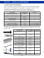
1.2 PARTS AND ACCESSORIES
Prior to operation, please remove all parts from the shipping container
and inspect for damaged or missing parts. If any parts are found to be
damaged or missing, please contact Omni International at
1-800-776-4431. The basic Macro ES consists of the following:
Description Part Number Quantity
Motor Drive Unit (115V) 1800DS-1 1
OR
Motor Drive Unit (220V) 1800DS-1 1
Instruction Manual 03-216 1
Stand Assembly LT500 1
Quick Connect Coupling Assembly 17210 1
Quick Connect Adapter 17204 1 (3 w/ MES Package)
Generator Probe Adapter 15001 1 (4 w/ MES Package)
The following components are supplied as part of the Macro ES Tool Kit
(P/N 17104):
Description Part Number Quantity
Gen Probe Multi Tool 00-402 2
20, 30, 45, 55mm Knife
Tool
15100K 1
1/16” Allen Wrench 00-416 1
5/64” Allen Wrench 60027 1
3/32” Allen Wrench 60128 1
1/8” Allen Wrench 60241 1
5/32” Allen Wrench 737 1
5/16” x 5/8” Combo
Wrench
60033 1
5mm Lower Bearing
Press
59105 1
7mm Lower Bearing
Press
59107 1
Lubricant 61971 1

7
SECTION 1 — MACRO ES HOMOGENIZER
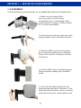
1.3 ASSEMBLY
Use the following instructions to assemble the Omni and Stand Unit.
1. Make sure you have all the
necessary parts: a) MES motor
assembly, b) post, c) threaded knob,
d) base plate assembly, e) Allen wrench,
& f) 3 screws (provided).
2. Attach the base plate to the post with
the provided screws and Allen wrench.
3. Place the MES motor unit onto the
post. Align the dowel pins on the MES
motor unit with the small pair of holes
in the post.
4. Seat the MES motor unit fully against
the post before adding the Threaded
Knob.
5. Insert the Threaded Knob into the
hole through the back of the post. Turn
the knob until the motor unit is securely
attached to the post. Hand tighten only.

8
SECTION 1 — MACRO ES HOMOGENIZER
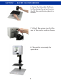
6. Raise the Movable Platform
to the desired level and secure
it with the positioning knob as
shown.
7. Attach the power cord to the
rear of the motor unit as shown.
8. The unit is now ready for
operation.

9
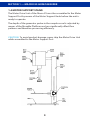
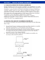
1.4 MOTOR SUPPORT STAND
The Motor Drive Unit of the Macro ES must be assembled to the Motor
Support Post by means of the Motor Support Knob before the unit is
ready to operate.
The depth of the generator probe in the sample vessel is adjusted by
means of the Movable Platform and can signicantly aect ow
patterns and therefore processing eciency.
CAUTION: To avoid product damage, never ship the Motor Drive Unit
while assembled to the Motor Support Post.
SECTION 1 — MACRO ES HOMOGENIZER

10
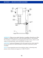
WARNING: When using sealed chamber assemblies, the bottom of the
chamber assembly must rest on the movable platform. This prevents
the chamber assembly from disengaging from the motor, which could
expose rotating blades, and could lead to a broken seal.
CAUTION: To prevent damage to the drive mechanism, never operate
the motor without a sealed chamber assembly or generator probe
installed.
NOTE: If you experience excessive vibration, heat, or bearing wear,
please contact technical support at 1-800-776-4431
SECTION 1 — MACRO ES HOMOGENIZER

11
SECTION 1 — MACRO ES HOMOGENIZER
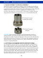
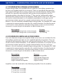
1.5 QUICK CONNECT COUPLING ASSEMBLY
The Quick Connect Coupling Assembly comes standard on the Macro
ES. To use, attach a Quick Connect Adapter to your chamber assembly
or generator probe (See Section 2 for more information). Next, slide the
Adapter into the Quick Connect Coupling and a retaining ring
positions into place for a secure hold. To disconnect, simply slide the
ring upward and the processing accessory is conveniently released.
CAUTION: Never operate the motor with the generator probe or
sealed chamber assembly partially attached to the Quick Connect
Coupling Assembly. To prevent damage to the motor and attachments,
follow the instructions in Section 2.2 to assure the generator probe or
sealed chamber assembly, Section 3.4 is fully connected to the Quick
Connect Coupling Adapter.
1.6 OPTIONAL AUTOMATED MOTOR SUPPORT STAND
An automated stand (PN 82010) can be substituted or retrotted in
place of the standard motor stand assembly (PN LT-500). This is a fac-
tory installed option, since the motor drive unit must be modied to
accommodate the automated stand controls. Upward and downward
motion is controlled by the control switch located on the lower right
side of the face plate. The speed of travel of the automated stand can
be adjusted by means of a screw driver adjustment potentiometer
located at the back of the motor drive unit.
17204 Quick Connect
Adapter
17210 Quick Connect
Coupling Assembly

12
SECTION 1 — MACRO ES HOMOGENIZER
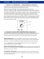
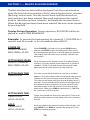
1.7 THEORY OF OPERATION—HOMOGENIZER CONTROLS
The Macro ES is controlled and programmed by means of an encoder input
(called control knob) working in conjunction with an
alpha-numeric LCD display screen. The control knob serves two
functions, selecting screens, and selecting parameters within each screen. In
the screen selection mode, turning the control knob moves the operator from
the SPEED to the TIME screens. When a desired screen is displayed, depressing
the control knob allows the operator to change to the screen parameter
selection mode. In this mode, turning the control knob clockwise increases
the screen parameter value (such as TIME or SPEED), while turning the control
knob counter-clockwise decreases the value. Once screen parameters have
been selected, pressing the control knob again changes its function back to
the screen selection mode.
1.8 VARIABLE SPEED AND VARIABLE TIME OPERATION
Speed and the operating time may be pre-selected and regulated to achieve
optimum results when working with dierent materials, and will remain
programmed for future operation, until reprogrammed by the operator.
Speed Selection: Turn on POWER to display the last selected speed.
Push and release the control knob. To increase speed, turn the control knob
clockwise, or reduce speed by turning the control knob counter-clockwise.
HOLD (Unlimited) Time Selection: Once speed has been selected, the
Macro ES can be operated for an indenite period of time by pressing RUN. To
terminate a run, press STOP.
Timed Run Operation: Select speed, then select run time by pushing
and releasing the control knob, then rotating the control knob to display the
time selection window.
NOTE: Sample viscosity and generator probe size may reduce top
speed attained for a given sample.

13
SECTION 1 — MACRO ES HOMOGENIZER
The last selected run time will be displayed. Push the control knob to
enter the time selection window 0:00:00, which displays hours, minutes
(ashing), and seconds. Turn the control knob until the desired run
time (minutes) has been entered, then push and release the control
knob to select the run time (seconds), and nally the run time (hours).
When the desired run times have been entered, the unit can be started
by pressing RUN.
Display During Operation: During operation, RUN SPEED will be dis-
played, as well as TIME REMAINING.
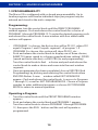
Example: To operate the homogenizer at a speed of 12,500 RPM for 2
minutes and 30 seconds, or for an indenite time (HOLD):
POWER ON
SPEED=1,000RPM
MAX SPEED=20,000
SETTING RUN SPEED
SPEED=12,500RPM
MAX SPEED=20,000
SETTING RUN TIME
TIME=0:02:30
SETTING RUN TIME
TIME=0:00:00
HOLD=00:00:00
HOLD
TIMER=HOLD
HOLD=00:00:00
When POWER is turned on, the green RUN button
and the red STOP button will alternately ash while
the homogenizer performs a brief diagnostic program.
The display will show the most recently selected run
parameters.
Follow the procedure above for setting Run Time until
all three time segments have been set to 0 as shown to
the left.
Push and release the control knob and the display will
read HOLD. Push RUN to operate the program. Push
STOP to end the program.
Push and release the control knob. The speed display
will ash, Turn the control knob clockwise to increase
speed to 12,500. Push and release the control knob
again and the display speed will stop ashing.
Turn the control knob clockwise until timer window
appears. Push and release the control knob, the minute
segment of the hour:minute:second display will ash.
Turn the control knob until the minute display reads 2
minutes. Push and release the control knob again and
the seconds display will ash. Turn the control knob
until the display reads 30 seconds. Push the control
knob twice, then press RUN to operate at 12,500 RPM
for 2 minutes and 30 seconds.

14
1.9 PROGRAMMABILITY
The Macro ES is congured with on board programmability. Up to
twelve programs with twelve individual steps per program may be
entered and stored in the units computer.
Programming:
To program, turn the control knob until the PRESET PROGRAMS
window appears. Push and release the control knob for a choice of
PROGRAM 1 through PROGRAM 12. To enter the desired program, push
and release the control knob. A new window with four addressable
sections will appear:
• If PROGRAM 1 is chosen, the rst section will be P01/01, where P01
equals Program 1 and 01 equals segment 1 of program 1. If
PROGRAM 2 is chosen, this section will show P02/01, etc. . .
• Push and release the control knob to display one of three choices,
RAMP TO (ramps speed to a chosen speed and time setting), SPEED
(speed and time selection), or END PRG (to end programming).
Turn the control knob to nd a choice and push and release the
control knob to make a choice and move into the next window
segment.
• Once programming has been completed, choose END PRG (End
Programming) by pushing and releasing the control knob when
END PRG ashes. A new window called EXIT VIEW MODE
appears. Push and release the control knob to access to Programs
1 through 12, as well as EXIT PROGRAM MODE. Choose a Program
number to enter additional programs or choose EXIT PROGRAM
MODE to return to manual operation.
Operating a Program:
• Turn the control knob until the PRESET PROGRAMS window
appears.
• Push and release the control knob and PROGRAM 1 appears.
Turn the control knob to choose PROGRAM 1 through PROGRAM
12, then press the RUN button and the unit will operate as
programmed.
SECTION 1 — MACRO ES HOMOGENIZER

15
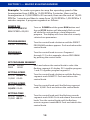
Example: To create a program to ramp the operating speed of the
homogenizer from 0 RPM to 10,000 RPM in 2 minutes, then run the
homogenizer at 10,000 RPM for 30 seconds, then run the unit at 15,000
RPM for 1 minute and then to ramp from 15,000 RPM to 1,000 RPM in 2
minutes requires 5 program segments as follows:
POWER ON
SPEED=1,000RPM
MAX SPEED=20,000
PROGRAMMING
PRESET PROGRAMS
PROGRAM 1
PROGRAM 1
SET PROGRAM SEGMENT
P01/01 SPEED
0000 00:00
SETTING SPEED
P01/01 RAMP TO
10,000 00:00
SETTING SPEED
P01/01 RAMP TO
10,000 00:00
SETTING TIME
P01/01 RAMP TO
10,000 02:00
Turn on POWER and the green RUN button and
the red STOP button will alternately ash on and
o while the unit performs a brief diagnostic
program. The display will show the most recently
selected run parameters.
Turn the control knob clockwise until the PRESET
PROGRAMS window appears. Push and release the
control knob.
Turn the control knob to access Programs I
through 12. For this example, choose PROGRAM I
by pushing the control knob.
Turn the control knob until the ashing segment
reads 10,000. Push and release the control knob.
Turn the control knob until the ashing seconds
segment reads 00:00. Push and release the control
knob. Turn the control knob until the ashing
minute segment reads 02:00. Push and release the
control knob.
Push and release the control knob to select the
ashing segment 01 display. P01 signies program
1 and /01 signies program segment 1.
Turn the control knob clockwise until the ashing
segment reads RAMP TO. Push and release the
control knob.
SECTION 1 — MACRO ES HOMOGENIZER

16
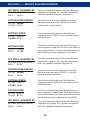
SET PROG. SEGMENT 02
P01/02 END PROGRAM
0000 00:00
SETTING SPEED MODE
P01/02 SPEED
10,000 00:00
SETTING SPEED
P01/01 SPEED
10,000 00:00
SETTING TIME
P01/01 SPEED
0000 00:30
SET PROG. SEGMENT 03
P01/03 END PROGRAM
0000 00:00
SETTING SPEED MODE
P01/03 SPEED
0000 00:00
SETTING SPEED
P01/03 SPEED
15,000 00:00
SETTING TIME
P01/03 SPEED
15,000 01:00
SET PROG. SEGMENT 04
P01/04 END PROGRAM
0000 00:00
Turn the control knob to select the ashing
segment 02 display. P01 signies program 1
and /02 signies program segment 2.
Turn the control knob clockwise until the
ashing segment reads SPEED. Push and
release the control knob.
Turn the control knob until the ashing
segment reads 10,000. Push and release the
control knob.
Turn the control knob to select the ashing
segment 03 display. P01 signies program 1
and /03 signies program segment 3.
Turn the control knob clockwise until the
ashing segment reads SPEED. Push and
release the control knob.
Turn the control knob until the ashing
segment reads 15000. Push and release the
control knob.
Turn the control knob to select the ashing
segment 04 display. P01 signies program 1
and /04 signies program segment 4.
Turn the control knob until the ashing sec-
onds segment reads 00:00. Push and release
the control knob. Turn the control knob until
the ashing minute segment reads 01:00.
Turn the control knob until the ashing sec-
onds segment reads 00:30. Push and release
the control knob. Turn the control knob until
the ashing minute segment reads 00:30.
SECTION 1 — MACRO ES HOMOGENIZER

17
SETTING RAMP MODE
P01/04 RAMP TO
0000 00:00
SETTING SPEED
P01/02 SPEED
500 00:00
SETTING TIME
P01/04 SPEED
500 02:00
SET PROG. SEGMENT 05
P01/05 END PROGRAM
0000 00:00
END PROGRAM MODE
P01/05 END PROGRAM
0000 00:00
EXIT PROGRAM MODE
EXIT VIEW MODE
OPERATING PROGRAM 1
PROGRAM 1
Turn the control knob clockwise until the
ashing segment reads RAMP TO. Push and
release the control knob.
Turn the control knob until the ashing
segment reads 500. Push and release the
control knob.
Turn the control knob until the ashing sec-
onds segment reads 00:00. Push and release
the control knob. Turn the control knob until
the ashing minute segment reads 02:00.
Turn the control knob clockwise until the
ashing segment reads END PROGRAM. Push
and release the control knob.
The display now reads EXIT VIEW MODE. Push
and release the control knob.
The display now reads PROGRAM 1. To operate
the program, push RUN. To select other preset
programs, turn the control knob.
Turn the control knob to select the ashing
segment 05 display. P01 signies program 1
and 05 signies program segment 5.
1.10 CIRCUIT BREAKER
In the event that the motor is overloaded during operation, the circuit
breaker, located at the rear of the motor drive unit may trip, and can be
easily reset.
1.11 EXTERNAL SPEED VERIFICATION
For independent speed verication of the speed display, remove the
black plug from the top of the motor drive housing, and verify speed
by means of a photo tachometer, reading directly from the top of the
motor drive shaft.
SECTION 1 — MACRO ES HOMOGENIZER

18
2.1 ROTOR-STATOR GENERATOR PROBES
Generator probes are available for use with the Macro ES but are not supplied
with the instrument. These probes can be used in a sealed chamber, or for
added convenience, in an open vessel environment when aerosols or sample
contamination are not a concern.
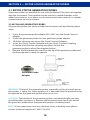
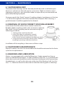
2.2 INSTALLING GENERATOR PROBES
All generator probes are easily installed to the motor unit by following these
steps:
1. Screw the generator probe adapter PN 15001 into the Quick Connect
adapter.
2. Screw the generator probe into the generator probe adapter.
3. Slide the retaining ring up on the Quick Connect Adapter.
4. Insert the Quick Connect Adapter into the Quick Connect Coupling
Assembly and slide the retaining ring down to lock the
generator probe in place (See diagram below).
5. Remove the blue protective cap from the tip of the generator probe and
the homogenizer is ready to operate.
WARNING: The tip of the generator probe, especially on the saw tooth gener-
ator probes, is sharp. For safety purposes it is advisable that the protective cap
be replaced on the generator probe when not in use.
CAUTION: The bottom of the generator probe is extremely fragile and care
should be taken to protect it. Replace the blue protective cap on the end of
the generator probe when the generator probe is not being used.
NOTE: If you experience excessive vibration, heat, or bearing wear, please
contact technical support at 1-800-776-4431
SECTION 2 — ROTOR-STATOR GENERATOR PROBES
Generator Probe
Adapter

19
2.3 OPERATION
Generator probes can be used in open containers or in sealed chamber
assemblies. Sample processing eciency is eected by:
• Amount of material processed vs. size and speed of the generator probe.
• Container geometry and size (round vessels encourage swirling, while
uted or cornered vessels disrupt ow patterns for more eective
mixing/processing.
• Processing speed optimal speed.
• Size and type of material and ow characteristics (material particles
must be small enough to be carried into the generator head for optimal
processing)
To operate the generator probe simply remove the blue protective cap from
the end of the generator probe. Keep the blue protective cap on the tip of the
generator probe when the generator probe is not being used.
CAUTION: When using Teon lower bearings, immerse the bottom of the
generator probe in liquid or in the sample to avoid premature failure of the
lower bearing.
WARNING: DO NOT process pathogenic material in an open container, since
aerosols created during normal processing could be inhaled by the operator.
NOTE: Liquid circulates through the two holes in the generator probe. DO
NOT block the upper hole, although the lower hole may be completely
submerged during processing.
NOTE: For optimal sample recovery during processing, completely remove
the generator probe from the sample prior to turning o the motor drive unit.
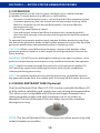
2.4 VESSEL RESTRAINT DISK (Optional)
The Vessel Restraint Disk (Part # LT-750) can be used with the Macro ES
to help reduce splashing and contain aerosols during homogenization.
This accessory is compatible with 20mm and larger diameter rotor-
stator generator probes and with containers up to six inches in
diameter. The Vessel Restraint Disk also helps secure the container
during processing.
NOTE: The Vessel Restraint Disk is not necessary when processing with
sealed chamber assemblies.
SECTION 2 — ROTOR-STATOR GENERATOR PROBES

20
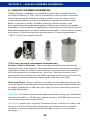
3.1 SEALED CHAMBER ASSEMBLIES
Sealed chamber assemblies are available as separately ordered items for
use with the Macro ES. They consist of chambers, many of which are uted
to facilitate mixing by inhibiting swirling, gasket screw on cover seals to
inhibit aerosol release, a shaft assembly, and a sharpened stainless steel
blade, or generator probe. Chamber materials include stainless steel,
glass, polycarbonate, and polypropylene. A full range of titanium chamber
assemblies is also available for applications requiring protection from leached
elemental components, or where additional strength is a factor. Please contact
your nearest Omni International representative, or Omni International at
1-800-776-4431 for complete details.
3.2 USING BLADE CHAMBER ASSEMBLIES
Stainless Steel or Titanium - These chamber assemblies are intended for
liquid and semi-solid materials. Homogenization and mixing will normally be
completed within 30 seconds to one minute. For processing solid materials,
rst reduce particle size diameter to 1cm or less. Load the material to be
processed in the chamber. Do not ll the chamber to full capacity. Processing
of too much volume could force liquid up through the rotor shaft.
Glass and Plastic - These chamber assemblies are intended primarily for low-
viscosity liquids or for light duty homogenization at speeds below 5,000 rpm.
At speeds greater than 5,000 rpm, place glass jar into a secondary container
for added protection.
WARNING: The maximum recommended speed when using any of the blade
chamber assemblies is 10,000 rpm. Speeds in excess of 10,000 rpm can cause
excessive bearing wear or part failure.
WARNING: Inspect glass or plastic chambers for any scratches or cracks, and
do not use if any are found. Eye protection and utilization of a secondary
container is recommended to prevent damage or injury in case of glass
breakage.
SECTION 3 — SEALED CHAMBER ASSEMBLIES
Page is loading ...
Page is loading ...
Page is loading ...
Page is loading ...
Page is loading ...
Page is loading ...
Page is loading ...
Page is loading ...
-
 1
1
-
 2
2
-
 3
3
-
 4
4
-
 5
5
-
 6
6
-
 7
7
-
 8
8
-
 9
9
-
 10
10
-
 11
11
-
 12
12
-
 13
13
-
 14
14
-
 15
15
-
 16
16
-
 17
17
-
 18
18
-
 19
19
-
 20
20
-
 21
21
-
 22
22
-
 23
23
-
 24
24
-
 25
25
-
 26
26
-
 27
27
-
 28
28


Ask a question and I''ll find the answer in the document
Finding information in a document is now easier with AI
Related papers
Other documents
-
 Omni International OMNI THq User manual
-
Omega HMG-11, 12, and HMG-13 Series Owner's manual
-
Benchmark Scientific D1000 Owner's manual
-
 Thermo Fisher Scientific PrioGENIZER Homogenation User guide
-
YSI 5300 Biological Oxygen Monitor Owner's manual
-
 Teledyne 6600 User manual
-
 Qiagen PowerLyzer 24 User manual
-
-
Ohaus HOHTDG Owner's manual
-
Kam KF Karl Fischer Moisture Analyzer User manual


