Page is loading ...

Crystal Vision Ltd., Lion Technology Park, Station Road East, Whittlesford, Cambridge, CB22 4WL, England.
E-mail: [email protected] Website: www.crystalvision.tv Tel: +44(0) 1223 497049 Fax: +44(0) 1223 497059
MON204
SDI to composite or Y/C monitoring
encoder

INTRODUCTION
The MON204 is an 8bit Serial Digital to Analogue Composite converter with selectable composite or
Y/C analogue outputs. The MON204 has two channels (channel Aand channel B). It is very compact
with 6modules fitting in a1U frame allowing monitoring of 12 SDI channels or 12 modules fitting in a2U
frame allowing monitoring of 24 SDI channels ,and therefore offers remarkable value for money. It will
accept either 625 or 525 line input on either channel, with automatic detection. Default outputs for either
channel are two analogue PAL/NTSC -two composite or one each of separate Y/C. The unit will plug
into the front of the rack frame, and the universal connection system will allow amixture of Crystal Vision
modules, in both 1U and 2U frames.
The hinged front panel of the case reveals user control of the card, and also LED indication of status. There
is an 8way piano switch that allows selection of some user options. Further configuration is possibleusing
movable links.
MON204 dual PAL/NTSC Encoder
USERS MANUAL
MON204m.dtp
mam issue 1.3
SPECIFICATION
Mechanical
100mm x266mm module with DIN 41612 connector. User adjustments and indication at end of board
to allow access from hinged front panel.
Weight: 150g
Number of channels 2-Channel Aand Channel B
Input: 270Mb/s serial digital to EBU Tech 3267-E &SMPTE 259M
Cable equalisation >200m Belden 8281 or equivalent
Auto or manual 525/625 selection on either channel Aor B.
Analogue Outputs: 2outputs per channel: Either composite(2) or separate Y/C.
Composite or Yplus syncs 1V into 75 Ohms, C300mV into 75 Ohms.
Frame OutputsNormally two composite for each channel .
or Separate Y/C for each channel
or one channel set to composite and the other set to separate Y/C
Composite or Y/C outputs are selected using movable links.
DIL switch selection of test pattern and vertical blanking for each channel
DIL switch selection of chroma bandwidth and 7.5 IRE setup is common for
both channels.
Analogue Performance:
Frequency Response:
Luminance +/- 0.2dB 0to 3.5Mhz +/- 0.3dB to 5MHz
Noise <-54dB weighted luminance or chrominance
Blanking To PAL/NTSC specification horizontally and vertically, with
selectable VBI blanking on or off. PAL lines 7to 22, and 320
to 335 and NTSC lines 10 to 20 and 273 to 282.
MON204 User Manual 19/5/00 page 1 of 8

OPTIONS AVAILABLE FROM FRONT PANEL
DIL SWITCH
1&6 Test Up outputs incoming data. Down sets the composite (or Y/C) output
to the inbuilt (modulated ramp) test pattern
2&7 PAL Up for 625 line and Down for 525 line if manual standard selected
on jumper J5/6.
3&8 VB Down leaves lines 7to 22, and 319 to 336 in PAL,
and lines 7to 20 and 270 to 278 in NTSC unblanked.
4SETUPDown selects setup. Only has any effect in 525 line operation and applies to
both channels. Adds 7.5 IRE of setup to Y, and reduces the Ygain as
required.
5CHRBW Up sets the chroma bandwidth to 1.3MHz, Down sets it to 650kHz. Setting
applies to both channels
GAIN CH-A There is an overall gain adjustment(composite and Y/C) for channal A. This
is set in the factory and should not need changing.
GAIN CH-B There is an overall gain adjustment(composite and Y/C) for channel B. This
is set in the factory and should not need changing.
FRONT PANEL LEDS (from left)
Green(upper) +5V Supply Voltage present
Yellow(lower) 525 input detected. Only valid if input present- channel A
Red(upper) Error Serial Digital Errors detected.- channel A
Green(lower) Input Present Valid Serial Digital input detected-channel A
Green(upper) -5V Supply Voltage present
Yellow(lower) 525 input detected. Only valid if input present- channel B
Red(upper) Error Serial Digital Errors detected. -channel B
Green(lower) Input Present Valid Serial Digital input detected-channel B
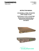
JUMPER SETTINGS
Jumper links are used to select several options. The position of the jumper links on the board is shown
below. The handle is on the left hand side of the board in the drawing. References to "upper" and "lower"
are with respect to this orientation.
J3
J4
J5
J6
J1
J2
Channel A
Channel B
MON204 User Manual 19/5/00 page 2 of 8

The position of the link on J5 for channel Aand J6 for channel Bselects either automatic or manual
choice of 525 or 625 line operation.
With the link on J5/6 in the upper position
the board will automatically adjust to the
video standard (525/625 line) of the in-
coming data. This may slightly extend the
time required to synchronise with anew
signal.
With the link on J5/6 in the lower
position the video standard used will
be set by the front panel DIL
switch.
J5 J5
Channel Ahas two analogue outputs which can be either both composite or Y/C.
Selection is made by moving both jumpers J1 and J3 in the same direction.
With J1 and J3 moved to the left position the outputs are composite.
With J1 and J3 moved to the rightt position the outputs are Yand C.
Channel Bhas two analogue outputs which can be either both composite or Y/C.
Selection is made by moving both jumpers J2 and J34 in the same direction.
With J2 and J4 moved to the left position the outputs are composite.
With J2 and J4 moved to the rightt position the outputs are Yand C.
MON204 User Manual 19/5/00 page 3 of 8

INSTALLATION INFORMATION
The MON204 plugs into the front of asuitable Crystal Vision frame. The standard 1U version is the
FR1-6 and the 2U FR2-12. These take 6and 12 modules respectively. The modules can be plugged into
and removed from the frame while it is powered without damage.
FixedConnection Frames
The connections on asix BNC per slot frame (FR1-6 &FR2-12) are:-
SDI/1 Channel ASerial Digital Input
SD2 Channel AComposite or Coutput
Y/G/OPA Channel AComposite or Youtput
U/B/OPB Channel BComposite or Youtput
V/R/OPC Channel BComposite or Coutput
SYNC/OPD Channel BSerial Digital Input
The connections on aten BNC per slot frame (FR2-8) are:
SDI/1 Channel ASerial Digital Input
SD2 Channel AComposite or Coutput
Y/G/OPA(1) Channel AComposite or Youtput
Y/G/OPA(2) Not Used
U/B/OPB(1) Channel BComposite or Youtput
U/B/OPB(2) Not Used
V/R/OPC(1) Channel BComposite or Coutput
V/R/OPC(2) Not Used
SYNC/OPD(1) Channel BSerial Digital Input
SYNC/OPD(2) Not Used
Configurable connection frames
Using REM01 rear module (6 BNCs occupying 1slot)
SDI(B) IN Channel BSerial Digital Input
PAL/Y(B) Channel BComposite or Youtput
PAL/Y(A) Channel AComposite or Youtput
PAL/C(A) Channel AComposite or Coutput
SDI(A) IN Channel ASerial Digital Input
PAL/C(B) Channel BComposite or Coutput
Rear Connectors
MON204 User Manual 19/5/00 page 4 of 8

Remote Connections
Inputs.
GPI inputs are normally puuled up to +5V relative to frame ground through ahigh (10K Ohm) resistance.
They will tolerate up to +35V relative to frame ground without damage.
Remote 0-connection 'a'
Relates to Channel A
Only active if manual standard selected on J5
OPEN -625 line mode
CONNECT TO GROUND -525 line mode
This is functionally similar to piano switch 2
Remote 1-connection 'b'
Relates to Channel A
OPEN -PAL lines 7-22 and 320-335 or NTSC lines 7-20 and 273-282 blanked
CONNECT TO GROUND -leaves these lines unblanked
This is functionally similar to piano switch 3
Remote 2-connection 'c'
Relates to Channel B
Only active if manual standard selected on J5
OPEN -625 line mode
CONNECT TO GROUND -525 line mode
This is functionally similar to piano switch 2
Remote 3-connection 'd'
Relates to Channel B
OPEN -PAL lines 7-22 and 320-335 or NTSC lines 7-20 and 273-282 blanked
CONNECT TO GROUND -leaves these lines unblanked
This is functionally similar to piano switch 3
Outputs
GPI outputs are 5V CMOS outputs via a330 Ohm resistor.
Remote 4- connection 'e'
Input Acarrier detected. Active low.
Remote 4- connection 'f'
Input Bcarrier detected. Active low.
MON204 User Manual 19/5/00 page 5 of 8

1U frame Remote 1
26 way high density D-type socket
This connector is used for remote control
Frame ground is pin 2
Slot Number
1
2
3
4
5
6
'a' pin number
8
7
5
4
3
10
'b' pin number
9
16
6
14
12
11
'c' pin number
18
17
15
13
22
19
'd' pin number
26
25
24
23
21
20
1U frame Remote 2
26 way high density D-type plug
This connector is used for remote indications of status
Frame ground is pin 6
Slot Number
1
2
3
4
5
6
'e' pin number
19
10
1
3
12
21
'f' pin number
20
11
2
4
13
22
MON204 User Manual 19/5/00 page 6 of 8

FR2-12 frame and FR2AV Remote 1(1) and Remote 3(3)
26 way high density D-type sockets
These connectors are used for remote control
Frame ground is pin 2in each case
Slot Number
1
2
3
4
5
6
7
8
9
10
11
12
'a' pin number
8(1)
7(1)
8(3)
7(3)
5(1)
4(1)
5(3)
4(3)
3(1)
10 (1)
3(3)
10 (3)
'b' pin number
9(1)
16 (1)
9(3)
16 (3)
6(1)
14 (1)
6(3)
14 (3)
12 (1)
11 (1)
12 (3)
11 (3)
'c' pin number
18 (1)
17 (1)
18 (3)
17 (3)
15 (1)
13 (1)
15 (3)
13 (3)
22 (1)
19 (1)
22 (3)
19 (3)
'd' pin number
26 (1)
25 (1)
19 (3)
25 (3)
24 (1)
23 (1)
24 (3)
23 (3)
21 (1)
20 (1)
21 (3)
20 (3)
FR2-12 frame and FR2AV Remote 2(2) and Remote 4(4)
26 way high density D-type plugs
These connectors are used for remote indication of input status
Frame ground is pin 6in each case
Slot number
1
2
3
4
5
6
7
8
9
10
11
12
'e' pin number
19 (2)
10 (2)
19 (4)
10 (4)
1(2)
3(2)
1(4)
3(4)
12 (2)
21 (2)
12 (4)
21 (4)
'f' pin number
20 (2)
11 (2)
20 (4)
11 (4)
2(2)
4(2)
2(4)
4(4)
13 (2)
22 (2)
13 (4)
22 (4)
MON204 User Manual 19/5/00 page 7 of 8

FR2-8 frame Remote Connections
Remote 1and Remote 2:26 way high density D-type sockets
Frame ground is pin 1in each case.
PSU relay connection on pin 10.
The table shows pin number (remote number)
Slot No 'a' pin no. 'b' pin no. 'c' pin no. 'd' pin no. 'e' pin no. 'f' pin no.
18(1) 9(1) 17(1) 18(1) 25(1) 26(1)
26(1) 7(1) 15(1) 16(1) 23(1) 24(1)
38(2) 9(2) 17(2) 18(1) 25(2) 26(2)
46(2) 7(2) 15(2) 16(2) 23(2) 24(2)
54(1) 5(1) 13(1) 14(1) 21(1) 22(1)
62(1) 3(1) 11(1) 12(1) 19(1) 20(1)
74(2) 5(2) 13(2) 14(2) 21(2) 22(2)
82(2) 3(2) 11(2) 12(2) 19(2) 20(2)
MON204 User Manual 19/5/00 page 8 of 8
/