
AMG Systems Ltd. reserves the right to make changes to this
document without notice. The information herein is
believed to
be accurate. No responsibility is assumed by AMG for its use.
Page
1
of
8
AMG5722
Instruction
Sheet
D17059
-
01.doc
AMG5722
Instruction Manual
Dual System with 2x Independent Channels each of :
[Single Channel Video Receive Unit for a Singlemode Fibre
Link]
The
AMG5722
is a
DUAL
standalone system which provides two independent channels, each
designed t
o receive one video signal over one Singlemode optical fibre. i.e. a total of two optical fibres.
The
AMG5722
is designed to be powered using an
AMG2001
standalone power supply.
The
AMG5722
is designed to operate with two
AMG5711
single channel video tra
nsmit units in a point
to point configuration.

AMG Systems Ltd. reserves th
e right to make changes to this
document without notice. The information herein is believed to
be accurate. No responsibility is assumed by AMG for its use.
Page
2
of
8
AMG5722
Instruction
Sheet
D17059
-
01.doc
Contents
Introduction
3
Unit Functional Schematic
................................
................................
................................
..................
3
Optical Connection
................................
................................
................................
.............................
3
Connections
4
Video Output Connections
................................
................................
................................
..................
4
Optical Connections
................................
................................
................................
...........................
4
Power Connection
................................
................................
................................
..............................
4
Front Panel Indicators
4
Power LED
................................
................................
................................
................................
..........
4
Physical Information
5
Dimensions
................................
................................
................................
................................
.........
5
Mounting Details
................................
................................
................................
................................
.
5
Removal / replacement from / to the Case
................................
................................
.........................
5
Safety
5
Maintenance and Repair
5

AMG Systems Ltd. reserves the right to make changes to this
document without notice. The information herein is believed to
be accurate. No responsibility is assumed by AMG for its use.
Page
3
of
8
A
MG5722
Instruction
Sheet
D17059
-
01.doc
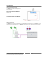
Introduction
Unit Functional Schematic
The
AMG5722
provides two independent,
receive channels.
Each channel receives one video signal
from up to two independent
AMG5711
transmi
t units.
The
schematic diagram shows one of the
two available channels of the
AMG5722
Optical Connection
The
AMG5722
connections are illustrated in the following example which shows two
AMG5711
single
channel transmit units together with an
AMG572
2
configured as a dual channel point to point system.

AMG Systems Ltd. reserves the right to make changes to this
document without notice. The information herein is believed to
be
accurate. No responsibility is assumed by AMG for its use.
Page
4
of
8
AMG5722
Instruction
Sheet
D17059
-
01.doc
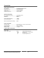
Connections
Video Output Connections
No. of channels
................................
....
2 independent video channels
Connectors
................................
..........
75 ohm BNC Socket.
Output Impedance
...............................
75 ohm terminated.
Output Level
................................
........
1 Volt p
-
p nominal
Frequency Respo
nse
...........................
10Hz to 7MHz.
Optical Connections
No. of Optical Connections
..................
1 per video channel
Optical Fibre
................................
........
Singlemode
Connector
................................
............
SC/PC
Primary Optical Sensitivity
...................
-
30dBm
Receive Wavelength
............................
1310nm
Minimum Optical Dynamic Range
.......
20dB.
Power Connection
Connect
or Type
................................
...
Removable 2
-
pin, 3.81mm, Screw Terminal
Connector Partno.
................................
Phoenix 1803578
Supply Voltage
................................
.....
+12 to +15 Volts DC
Maximum Power
................................
..
1.5 Watts
Front Panel Indicators
Power LED
Power / Video / Opto
............................
Green
-
Video present & opto sync.
R/G
-
Opto sync. but n
o video present.
Red
-
No opto sync.
Off
-
No power applied to unit.

AMG Systems Ltd. reserves the right to make cha
nges to this
document without notice. The information herein is believed to
be accurate. No responsibility is assumed by AMG for its use.
Page
5
of
8
AMG5722
Instruction
Sheet
D17059
-
01.doc
Physical Information
Dimensions
Height
................................
..................
112mm
Width
................................
...................
170mm (excluding connectors)
Depth
................................
...................
35mm
Weight
................................
.................
600grams
Mounting Details
The AMG unit is supplied with a clip
-
on mounting bracket
which should be attached to a panel or wall
using 2 off 4.0mm screws, see diagram on page 1 for dimensions. The unit is clipped into the
mounting bracket, and is then held firmly in position.
Removal / replacement from / to the Case
Note:
-
The AMG unit
PCB is static sensitive. Handle with proper care and use normal electrostatic
discharge (ESD) procedures. Use properly grounded protection (for example, wrist straps) when
handling the PCB out of the case.
To remove the PCB from the case for example to a
ccess a Low Speed Data mode switch, remove the
2 fixing screws on the rear panel and slide the PCB sufficiently out of the case to enable access to the
switch.
To replace the PCB into the case, slide the PCB gently into the case, if necessary aligning th
e board
with the appropriate slots.
Safety
AMG Optical Fibre Products use Class 1 laser systems in accordance with EN 60825
-
2:2000.
It is always advisable to follow good practice when working with optical fibre systems. This includes:
Do not stare wit
h unprotected eyes or with any unapproved collimating device at fibre
ends or connector faces, or point them at other people.
Use only approved filtered or attenuating viewing aids
For other safety issues and advice on good practice associated with optica
l fibre systems, please see
EN 60825
-
2:2000 or your local safety officer.
Maintenance and Repair
There are no user serviceable parts within AMG products. See unit data sheet for full specification.
In case of problem or failure, please call your local
support centre or contact:
AMG Systems Ltd.
at
3 The Omega Centre, Stratton Business Park, Biggleswade, Beds., SG18 8QB, UK.
Phone
+44 (0) 1767 600 777
Technical Support
+44 (0) 1767 604 491
Email
techsupport@amgsystems.com

AMG Systems Ltd. reserves the right to make changes to this
document without notice. The information herein is believed to
be accurate. No responsibility is assumed by AMG for its use.
Page
6
of
8
AMG5722
Instruction
Sheet
D17059
-
01.doc
This
page is intentionally blank.

AMG Systems Ltd. reserves the right to make changes to this
document without notice. The information herein is believed to
be accurate. No respon
sibility is assumed by AMG for its use.
Page
7
of
8
AMG5722
Instruction
Sheet
D17059
-
01.doc
This page is intentionally blank.

AMG Systems Ltd. reserves the right to make changes to this
docume
nt without notice. The information herein is believed to
be accurate. No responsibility is assumed by AMG for its use.
Page
8
of
8
AMG5722
Instruction
Sheet
D17059
-
01.doc
This page is intentionally blank.
-
 1
1
-
 2
2
-
 3
3
-
 4
4
-
 5
5
-
 6
6
-
 7
7
-
 8
8


Ask a question and I''ll find the answer in the document
Finding information in a document is now easier with AI
Related papers
-
AMG AMG5712-7hp Instruction Sheet
-
-
-
-
-
-
-
-
-