
KNX Product Documentation Seite: 1 von 31
Hardware description
KNX Switch Act. 16A FM w.2 Inputs Actuator
Product name: Switch Actuator 16A FM, with 2 Inputs
Design: FM (flush-mounted type)
Article-no.: MTN6003-0001
ETS search
path: 4.1 Switch Actuator, 1-gang / 4.1.01 Flush-mounted UP
Issue: 20.09.2010
Functional description:
The switching actuator receives telegrams from sensors via the Instabus and switches an electrical load with its
relay-output.
The device is equipped with two extension inputs which - depending on parameterization - can act directly on the
switching output (local control / only input 1, input 2 without function) or alternatively as binary inputs on the
Instabus KNX / EIB. The connected potential-free switch or push-button contacts are sensed against a common
reference potential at the switching actuator. As a binary input, the device can transmit telegrams for switching or
dimming, for shutter/blind control or for value transmitter applications (dimming value transmitter, light-scene
extension). Connecting 230 V signals or other external voltages to the extension inputs is not permitted.
The switching actuator is supplied from the Instabus and needs therefore no additional external power supply.
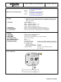
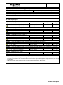
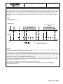
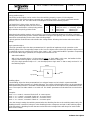
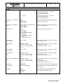
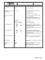
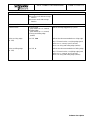
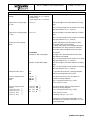
Illustration: Dimensions: Controls:
Prog.
EIB+ / RD
EIB- / BK
1 / GN
com / WH
2 / YE
com / BN
µ
BN
BN
LL'
A
B
C
Ø: 53 mm
Height (H): 28 mm
Opening for ceiling rose:
Ø: 7 mm
A Low-voltage connecting wires
red (RD): bus (+)
black (BK): bus (-)
green (GN): extension input 1
white (WH): reference potential (com)
yellow (YE): extension input 2
brown (BN): reference potential (com)
B Load connection wires
2 x brown (BN): L and L' (switching output)
C: Programming button / LED (red)
Technical data
Medium: TP1
Commissioning mode: S-mode
Type of protection: IP 20
Safety class: III
Mark of approval: KNX / EIB
Ambient temperature: -5 °C ...+45 °C
Storage / transport temperature: -25 °C ...+70 °C (storage above +45 °C results in shorter lifetime)
Mounting position: any
Minimum spacings: none
Type of fastening: e.g. placing into deep flush-mounting box (∅ 60 mm x 60 mm)
Instabus EIB supply
Cable type: YY 6 x 0.6 mm; red: bus (+) / black: bus (-)
Voltage: 21 – 32 V DC SELV
Power consumption: typically 150 mW
Connection: approx. 33 cm ready-made; connecting terminal (0.6 – 0.8 mm)
External supply ---

KNX Product Documentation Seite: 2 von 31
Hardware description
Response to voltage failure: Output: depending on parameterization
(cf. "parameter description")
Inputs: no reaction
Response to bus voltage return: Output: depending on parameterization
(cf. "parameter description")
Inputs: depending on parameterization
(cf. "parameter description")
Input:
Number: 2 (depending on parameterization either as extension inputs for push
button local control of the actuator or as independent binary inputs
acting on the bus)
Cable type: YY 6 x 0.6 mm
green: extension input 1
white: reference potential (com)
yellow: extension input 2
brown: reference potential (com)
Cable length: approx. 33 cm ready-made, extendible to 5 m max.
Scanning voltage: approx. – 19 V DC referred to "com"; continuous signal
Loop resistance: max. 2 kOhm for safe "1" signal detection (rising edge)
Output:
Number: 1
Cable type: 2 x H05 V-K 2.5 mm² with ferrules
Cable length: approx. 20 cm ready-made
Switch type: make-contact, potential-free (µ-contact), bistable
Switching voltage: 230 V AC; 50 / 60 Hz
Max. switching current: 16 A
Max. inrush current: 400 A, 20 ms
Switching capacity: Incandescent lamps: 2.500 W (at 100,000 switching operations)
HV halogen lamps: 2.200 W (at 100,000 switching operations)
LV halogen lamps
inductive transformers: 1.000 VA
electronic transformers: 1.000 W
capacitive loads: 230 V AC, 10A switching current,
max. 105 µF
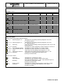
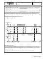
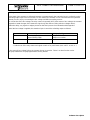
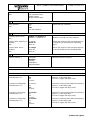
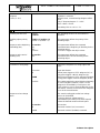
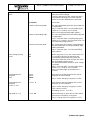
Connecting diagram: Terminals:
Load connection:
L1
L2
L3
N
Prog.
EIB+ / RD
EIB- / BK
1 / GN
com / WH
2 / YE
com / BN
µ
BN
BN
LL'

KNX Product Documentation Seite: 3 von 31
Hardware description
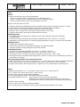
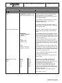
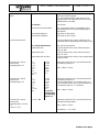
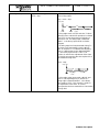
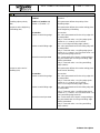
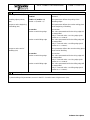
Connecting diagram: Terminals:
Bus connection and connection of extensions:
COM
COM
1
2
U = approx. -19 V
com
UCOM
UCOM
+ red
- black
green
white
yellow
brown
EIB / KNX
input 1
input 2
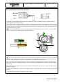
A spacing of 4 mm minimum between extra low-voltage lines (bus and extension inputs) and the load lines
(230 V) must be ensured (see fig. A).
It is recommended to install the switching actuator in two interconnected flush-mounting boxes (see fig. B). One
of the boxes (A) can accomodate besides the bus and extension connections also a series switch (C), whereas
the other box (B) accomodates the switching actuator and the 230 V terminals. The 6-wire connecting cable (D)
is led through the box junction.
The 'COM' potential must not be connected together with potentials from other sources - not even other
'COM' connections from additional flush-mounted actuators!
230 V
Bus/Com/1,2
min. 4 mm
Fig A
A
230 V
B
C
D
µ
µ
GYPKBK
L1 2
Fig B
Hardware information
• Never connect the mains voltage (230 V) or other external voltages to the extension inputs. Connecting an
external voltage endangers the electrical safety of the entire KNX/EIB system (SELV / no electrical insulation).
Persons may be put at risk and devices and installations may suffer irreparable damage.
• Make sure during the installation that there is always sufficient insulation between the mains voltage and the
bus or the extensions. A minimum spacing of 4 mm must be ensured between the bus/extension wires and the
mains wires.
• Non-used wires of the 6-wire connecting cable must be insulated with respect to one another and with respect
to external voltages.
• To avoid EMC disturbances, the lines to the inputs should not be laid parallel to lines and cables carrying mains
voltage.
• Connection of different phase conductors is not possible!

KNX Product Documentation Seite: 4 von 31
Software description
Software description
ETS search path:
4.1 Switch Actuator, 1-gang / 4.1.01 Flush-mounted UP
ETS symbol:
1
PEI Type 00 Hex 0 Dez No adapter used
Applications:
No. Short description: Name: Version:
1 1-channel switching with time functions, feedback and
additional functions. Two additional extension inputs. Switching FM 207201 0.1

KNX Product Documentation Seite: 5 von 31
Software description
Application: 1. Switching FM 20720
1.2
Executable from mask version:
Number of addresses (max): 26 dynamic table handling Yes : No
Number of assignments (max): 27 maximum length of table 53
9
Communication objects:
Objects for the binary inputs (extension inputs), if acting on the bus:
Function: no function (for all 2 inputs 2)
No further input objects
Function: "Switching" (for all 2 inputs 2)
Object Function Name Type Flag
C, W, T, (R) 1
2 – 3 Switching object X.1 (X = 1 to 2) Input 1 – Input 2 1 bit C, W, T, (R) 1
10 - 11 Switching object X.2 (X = 1 to 2) Input 1 – Input 2 1 bit
Function: "Dimming" (for all 2 inputs 2)
Object Function Name Type Flag
C, W, T, (R) 1
2 – 3 Switching Input 1 – Input 2 1 bit C, T, (R) 1
10 - 11 Dimming Input 1 – Input 2 4 bit
Function: "Shutter/blind" (for all 2 inputs 2)
Object Function Name Type Flag
C, T, (R) 1
2 – 3 Short operation (STEP) Input 1 – Input 2 1 bit C, T, (R) 1
10 - 11 Long operation (MOVE) Input 1 – Input 2 1 bit
Function: "Value transmitter" (Function: Dimming value transmitter for all 2 inputs 2)
Object Function Name Type Flag
C, T, (R) 1
2 – 3 Value Input 1 – Input 2 1 byte
Function: "Value transmitter" (Function: Light-scene extension with / without storage function for all 2 inputs 2)
Object Function Name Type Flag
C, T, (R) 1
2 – 3 Light-scene extension Input 1 – Input 2 1 byte
Function: Disable (for all 2 inputs 3)
Object Function Name Type Flag
C, W, (R) 1
18 - 19 Disabling Input 1 – Input 2 1 bit
1: Objects marked (R) permit read-out of the object status (set R flag).
2: The "No function", "Switching", "Dimming", "Shutter/blind" and "Value transmitter" functions can be selected
per input. The names of the communication objects and the object table (dynamic object structure) will change
accordingly.
3: A disable function is not available if the inputs are parameterized for "No function"

KNX Product Documentation Seite: 6 von 31
Software description
Objects for the output:
Function: Output
Object Function Name Typ Type Flag
C, W, (R) 1
0 Switching Output 1 - 2 1 bit 1.001
Function: Additional function for the output = "Logic-operation object"
Object Function Name Typ Type Flag
C, W, (R) 1
8 Logic function Output 1 - 2 1 bit 1.001
Function: Additional function for the output = "Disabling object"
Object Function Name Typ Type Flag
C, W, (R) 1
8 Disabling Output 1 - 2 1 bit 1.003
Function: Additional function for the output = "Priority-position object"
Object Function Name Typ Type Flag
C, W, (R) 1
8 Priority operation Output 1 - 2 2 bit 2.001
Function: Feedback for the output
Object Function Name Typ Type Flag
C, T, (R) 1
16 Feedback Output 1 - 2 1 bit 1.001
1: Objects marked (R) permit read-out of the object status (set R flag).
Object description
Objects for the binary inputs (extension inputs):
2 – 3 Switching object X.1: 1-bit object for transmitting switching telegrams (ON, OFF)
(1st switching object)
10 – 11 Switching object X.2: 1-bit object for transmitting switching telegrams (ON, OFF)
(2nd switching object)
2 – 3 Switching: 1- bit object for transmitting switching telegrams (ON, OFF) for the
dimming function
10 – 11 Dimming: 4-bit object for relative brightness variation between 0 and 100 %
2 – 3 Short operation (STEP): 1-bit object for STEP operation of a shutter or blind
10 – 11 Long operation (MOVE): 1-bit object for MOVE operation of a shutter or blind
2 – 3 Value: 1-byte object for transmitting value telegrams (0 - 255)
2 – 3 Light-scene extension 1-byte object for recalling and storing light-scenes (1 - 64)
18 – 19 Disabling: 1-bit object for disabling individual binary inputs
(polarity parameterizable)
Objects for the output:
0 Switching: 1-bit object for controlling the output
8 Logic operation: 1-bit object for logic-operation control of the output
(ON: Logic-operation input "1" / OFF: Logic-operation input "0")
8 Disabling: 1-bit object for disabling the output
(polarity parameterizable)
8 Priority control: 2-bit object for prioritary priority-position control of the output
16 Feedback: 1-bit object for switching status feedback of the output
(feedback invertible)

KNX Product Documentation Seite: 7 von 31
Software description
Scope of functions
Inputs:
General
• Mode of functioning of the inputs parametrizable:
- function as extension inputs acting directly on the switching output
(input 1 Æ output / input 2 Æ without function) (state-of-delivery setting)
- function as general binary inputs acting separately on the bus
Function as binary inputs to the bus:
• Switching, dimming, shutter/blind and value transmitter functions freely assignable to the max. 2 inputs
• Disable object for disabling of individual inputs (polarity of disable object presettable)
• Delay on return of bus voltage and debouncing time centrally adjustable
• Response to bus voltage return separately parameterizable for each input
• Telegram rate limitation generally parameterizable for all inputs
Switching function
• Two independent switching objects available for each input (switching commands individually
parameterizable)
• Command for rising and falling edge individually adjustable (ON, OFF, TOGGLE, no reaction).
• Independent cyclical transmission of switching objects depending on edge or on object value selectable.
Dimming function
• Single-sided and double-sided actuation
• Time between dimming and switching and dimming step width presettable
• Telegram repetition and stop telegram transmission possible
Shutter/blind function
• Command for rising edge adjustable (no function, UP, DOWN, TOGGLE)
• Operation concept parameterizable ("step - move – step" resp. "move – step")
• Time between STEP and MOVE operation presettable (only with "step - move - step")
• Slat adjustment time presettable (time during which a "MOVE" command can be terminated by releasing a
push-button on the input)
Value transmitter and light-scene extension functions
• Edge (push-button as n.o. contact, push-button as n.c. contact, switch) and value for edge parameterizable
• Value change in push-button mode possible with long press on the button for value transmitter
• In light-scene extension with storage function, a light-scene can be stored withous preceding recall
Output:
• Output parameterizable as n.o. contact (ON: contact closes / OFF: contact opens) or
as n.c. contact (ON: contact opens / OFF: contact closes)
• Preferred state on return of bus voltage presettable
• For the output additional feedback and additional function possible:
Presettable additional functions: - logic-operation function with 3 logic parameters
- disabling function with presettable disabling behaviour of the relays
- priority-position function to fix the priority of arriving switching telegrams
• Feedback object invertible
• Delay on return of bus voltage centrally presettable
• Turn-on delay and/or turn-off delay or timer function separately presettable for each output

KNX Product Documentation Seite: 8 von 31
Software description
Functional description of the inputs
Mode of functioning of the inputs
The switching actuator is equipped with two extension inputs which - depending on parameterization - can act
directly on the switching output (local control) or alternatively as binary inputs on the Instabus EIB/KNX.
In the state as delivered (unprogrammed actuator), the extension inputs act directly on the switching output. This
means that the actuator can be commissioned and operated already 'on site' simply by connecting the bus
voltage and without further sensors.
• Inputs acting on the switching output
The extension inputs act like an external sensor only internally directly on the switching output. Input 1 controls
the output. Input 2 has no function. In this case the parameter "Signal control" defines the signal evaluation, so
that making-contacts or breaking-contacts can be attached to the first input.
In acc. with the parameter "Mode" (n.o. or n.c. switching output), the relay output react as follows:
Signal (edge) control Contact at input Mode Relay switching state
Push button closed (rising edge) n.o. / n.c. Contact toggles *
(rising: TOGGLE / falling: ---) opened (falling edge) n.o. / n.c. No reaction
Switch closed (rising edge) n.o. Contact closes
(rising: ON / falling: OFF) opened (falling edge) n.o. Contact opens
closed (rising edge) n.c. Contact opens
opened (falling edge) n.c. Contact closes
Switch closed (rising edge) n.o. / n.c. Contact toggles *
(rising: TOGGLE / falling: TOGGLE) opened (falling edge) n.o. / n.c. Contact toggles *
*: The object value of the switching object (object nummer "0") is toggled. A normally-opened contact (n.o.) is
closed at "1" and opened at "0". A normally-closed contact (n.c.) is closed at "0" and opened at "1".
For direct action, the extension inputs do not have parameters of their own so that the parameter cards for the
inputs are not available.
After return of bus voltage, the actuator responds to changes of the extension signal state only after the time
parameterized for the "Delay on return of bus voltage" has elapsed.
During the delay, pulse edges or signals present at the inputs are not evaluted and disregarded. The time of
delay is generally parameterized for all inputs and also for the output.
It is possible to parameterize a general telegram rate limitation. In this case, no switching-feedback telegram is
transmitted within the first 17 s after bus voltage return when the output are controlled by the extension inputs
during this time.
• Inputs acting separately on bus
The inputs of the switching actuator act independently of the switching output and separately on the Instabus
KNX/EIB. Depending on parameterization, the functions "Switching", "Dimming", "Shutter/blind" or "Value
transmitter" can be selected for each input (cf. "Parameter description"). When "No function" is selected, the
corresponding input is deactivated.
When the "Switching" setting is selected, the extension objects can be combined via group addresses with the
object of the switching output. The actuator can thus be controlled via its own inputs even if the extension
signals are set for acting on the bus (e.g. group control of several actuators).
The functional description of the inputs on the following pages is valid only if the extensions are set for acting on
the bus!

KNX Product Documentation Seite: 9 von 31
Software description
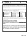
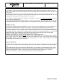
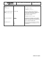
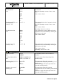
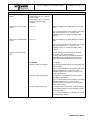
Dimming value transmitter: change by means of long key press
In the event of dimming value transmitter parameterization, the value to be transmitted can be changed by means
of a long key-press (> 5 s) if the the value is to be transmitted on the rising or the falling edge. In this case, the
programmed value is increased by the parameterized step width and transmitted. After releasing of the input
contact, the value last transmitted remains stored. On the next long key-press, the direction of value change is
reversed.
Example:
Value (0...255) 17
Step width (1...10) 5
time
edge at input
value change
value variation direction
change
5 s
time
value = 17 17
17 2 0 0
2 7 12
17
time between
two telegrams
> 5 s
< 5 s
bus
telegram
0
12 7
value change
no further change
minimum value reached
Important:
- During value variation there is no overrun and no underrun. When the maximum (255) resp. the minimum (0)
value is reached, no more telegrams are transmitted.
- To ensure that the concerned lighting switches off or on with the max. value during value variation, the limit
values (values "0" resp. "255") are always transmitted when the limits of the variation range are reached. This is
also the case when the parameterized step width does not directly account for these values (cf. example above:
step width = 5; value "2" is transmitted, thereafter value "0").
To ensure that the original starting value can be set again during a new change (change of variation direction),
the first value jump will not correspond to the preset step width (cf. example above: step width = 5; value "0" is
transmitted, thereafter values "2", "7" etc.).
- When values are changed, the newly set values are stored in the RAM.
After a bus voltage failure or a bus reset, the changed values will be replaced by the values originally
parameterized in the ETS.

KNX Product Documentation Seite: 10 von 31
Software description
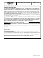
Light-scene extension with / without storage function
In a parameterization as light-scene extension without storage function it is possible to recall a light-scene. In
case of a rising edge, a falling edge or a rising and a falling edge, the parameterized light-scene number is
transmitted immediately.
In a parameterization as light-scene extension with storage function it is possible to generate a storage telegram
depending on the light-scene to be transmitted. A long actuation of the n.o. contact (rising edge) or of the n.c.
contact (falling edge) causes the corresponding storage telegram to be transmitted. In this case, the time for a
long press is parameterizable (however not below 5 s). After a short press < 1 s, the parameterized light-scene
number (without storage telegram) is transmitted. If the actuation is longer than 1 s, but shorter than 5 s, no
telegram will be transmitted at all. In addition, it is possible to transmit only a storage telegram without preceding
light-scene recall. In this case, the "Storage function only" parameter must be set to "YES".
Examples for light-scene extension with storage function:
1.) storage function only = NO
2.) storage function only = YES
tim
e
tim
e
bus
telegram
light-scene
storage
storage
< 1 s 1 s to 3 s
5 s
edge at input
undefined input
no telegram
light-scene
recall
tim
e
Bus-
telegramm
light-scene
storage
light-scene
storage light-scene
storage light-scene
storage
1.)
2.)
light-scene
recall
storage function only = NO:
If a rising or a falling edge is detected at the input (depending on parameterization), the timer is started. If the key
is released within the first second, the corresponding light-scene is recalled immediately. If the key is pressed
longer, the storage telegram is transmitted after 5 s.
storage function only = YES:
The storage telegram is transmitted immediately after detection of the corresponding edge.

KNX Product Documentation Seite: 11 von 31
Software description
Response to return of bus voltage
It is possible to define separately for each input whether a reaction or what kind of reaction is to take place on
return of bus voltage so that a defined telegram can be transmitted to the bus depending on the input signal or by
forced control.
The defined reaction takes place only after the parameterized "Delay on return of bus voltage" has elapsed.
While the delay is active, any edges or signals present at the inputs are not evaluated and disregarded. The delay
is generally parameterized for all inputs and also for the output.
It is possible to parameterize a general telegram rate limitation. In this case, no telegram is transmitted within the
first 17 s after bus voltage return.
It should be noted that the parameterized "Delay on return of bus voltage" is active also during this time and that
the parameterized reaction on bus voltage return is not executed if the delay elapses within the first 17 seconds.
Disabling function
Each input can be independently configured for a certain reaction at the beginning or at the end of disabling. It is
also possible to parameterize the input for "No reaction". Only in this case will dimming or shutter control
procedures or value changes in progress before activation of the disable function continue to be executed until
the end when disable is active. In all other cases, the parameterized command will be transmitted immediately at
the beginning of disable. During an active disable, edges or signals at the corresponding inputs are not evaluated.
Updates on disable objects (disable or enable) will always lead to the transmission of the corresponding
command parameterized for "the beginning resp. the end of disabling".
During an active disable, no cyclical transmission takes place via the disable input.
If cyclical transmission did take place before activation of the disable function, no cyclical transmission will take
place anymore at the end of disable when "No reaction" is parameterized. In this case, the object value will again
be transmitted cyclically only after an update on the switching object. In all other cases, the object value will again
be transmitted cyclically after the end of disable.
Cyclical transmission
The object value transmitted is always the object value internally or externally followed up in the switching objects.
For this reason, the object value is transmitted cyclically even if "No reaction" is assigned to a rising or a falling
edge.
Cyclical transmission takes place also directly after the return of bus voltage, if the parameterized value of the
telegram after bus voltage return corresponds to the object value parameterization for cyclical transmission. If
telegram rate limitation is enabled, cyclical transmission will take place at the earliest after 17 seconds.
During an active disable, no cyclical transmission takes place via the disabled input.

KNX Product Documentation Seite: 12 von 31
Software description
Functional description for the output
Response to return of bus voltage
The response to bus voltage failure can be defined. In this case, the contact can open or close (setting: "Close
contact" or "Open contact"). The "Mode" parameter (normally open or normally closed) is irrelevant in this case.
In the "None" setting, the relay-status is not effected by the bus voltage failure
Additionally the preferred state of the switching output on return of bus voltage can be defined. In this way, the
switching output closes or opens (setting: "Close contact" or "Open contact"). The "Mode" parameter (normally
open or normally closed) is irrelevant in this case, too.
The switching state that was active before bus voltage failure (setting: "Value before bus voltage failure") can
moreover be followed up. Timer or other activated logic-operation functions which may have been started before
bus voltage failure will not be accounted for.
The switching state set after return of bus voltage will be followed up in the feedback object and in the switching
object.
The defined response to bus voltage return will be triggered only after the parameterized "Delay on bus voltage
return" has elapsed. Within the delay period, the output shows no reaction. Updates of the switching object via
the bus during the delay period will be stored and executed only after the end of the delay.
It is possible to parameterize a general telegram rate limitation. In this case, no telegram will be transmitted via
the feedback object within the first 17 s after bus voltage return.
The switching output can nevertheless be actuated via the switching object as soon as the "Delay on bus voltage
return" has elapsed.
A Disabling function or a priority position activated before bus voltage failure is always deactivated after return of
bus voltage.
Feedback object
When the switching state of the output changes, the current switching state is transmitted to the bus via the
corresponding feedback object.
The feedback object value is updated also after return of bus voltage when the parameterized delay period has
elapsed and is actively transmitted to the bus. With telegram rate limitation being enabled, no telegram will be
transmitted via the feedback object within the first 17 s. The feedback signal is stored and then executed after the
17 s delay has elapsed.
It may be possible to read out the object status by means of a display software (set R flag!).

KNX Product Documentation Seite: 13 von 31
Software description
Additional functions
Priority-position object:
The priority-position object can be used to force the switching output by means of 2-bit telegrams
independently of the switching object separately into a switching position. The "Mode" parameter remains
effective in this case, too. The value of the 2-bit telegram must have the following sysntax:
The first bit (bit 0) of the priority-position object Bit 1 Bit 0 Function
determines the switching state to be forced on the 0 x Priority not active, Ö ´switching´ object
output. The second bit (bit 1) of the priority-position 0 x Priority not active, Ö ´switching´ object
object enables the priority-position mode. 1 0 Priority active switching off
1 1 Priority active switching on
When the priority-position mode is active (priority), any incoming switching telegrams will still be evaluated
internally. When the priority-position mode is thereafter no longer active (priority), the current internal switching
state will be set depending on the value of the switching object.
A priority-position mode that was active before bus voltage failure will always be inactive after return of bus
voltage.
Logic-operation object:
If the logic-operation object has been parameterized, it is possible to implement a logic operation on the
switching object of the corresponding output. In this case, the object values of the logic-operation object and of
the switching object are combined by means of the "AND" / "OR" / "AND with feedback" operations. Depending
on the result of these logic operations, the output will be activated or not.
AND with feedback:
With a logic-operation object = "0" the output is always "0" (logic AND). In this case, the feedback of the
output to the switching object, resets the switching object when it is being set.
Only if the logic-operation object = "1", can the output pass to logic state "1" after a newly received "1" on
the switching object.
&
Feedback
Switching
Logic-operation
Output
Disabling object:
If the disabling object has been parameterized, an assigned output can be locked in a parameterizable
switching position after reception of a disable telegram. The polarity of the disabling object can be preselected.
When the disabling function is activated or deactivated, the response of the output can be predefined for both
cases. The output can either switch on or switch off. The "Mode" parameter must be taken into account in this
case.
Examples:
Mode = "n.o. contact", command "Switch off" Æ contact opens,
Mode = " n.o. contact", command "Switch on" Æ contact closes,
Mode = "n.c. contact", command "Switch off" Æ contact closes,
Mode = "n.c. contact", command "Switch on" Æ contact opens.
In the "No change" setting, the switching status before the disabling function or the switching status set by the
disabling function is retained. During an active disabling function, telegrams received via the switching object
will be discarded. A disabling function that was active before bus voltage failure will always be inactive after
return of bus voltage.

KNX Product Documentation Seite: 14 von 31
Software description
Delivery state
In the state of the actuator as delivered (actuator not programmed), the extension input 1 act directly on the
switching output. Input 2 has no function. For this reason, the actuator can be commissioned and operated
already 'on site' only by connecting the bus voltage and without needing sensors.
On connection of the bus voltage, the relay contact ist opened (OFF). After return of bus voltage, the actuator
responds to state changes of the extension signal only after 390 ms (delay after bus voltage return).
Within the delay, any signals or edges present on the first input are not evaluated and disregarded.
When the bus voltage is applied, the extension input 1 control the switching output as follows:
Input Contact at input Relay switching state
1 Closed (rising edge) Output: TOGGLE *
Opened (falling edge) Output: no reaction
2 No function!
*: Switch-over of the relay-status and signal control as for push button (ON Æ OFF Æ ON Æ ...)
In the event of bus voltage failure, the actuator shows no reaction. There is no time function active.
No group addresses are preprogrammed at factory default.

KNX Product Documentation Seite: 15 von 31
Software description
Parameters
Description Values: Comment:
General
Mode of functioning of
inputs
inputs acting on switching
output (E1 -> A1 / E2 -> ---)
inputs acting separately on bus
Defines whether the extension inputs of the
actuator act directly on the switching output
(local operation) or, as an alternative,
separately from each other as binary inputs on
the Instabus KNX/EIB.
Only if "Mode of functioning of inputs = inputs
acting separately on bus " are the input
parameter cards active.
The setting " Mode of functioning of inputs =
inputs acting on switching output" corresponds
to the delivery state.
Signal control of the inputs
Push button
(rising = TOGGLE;
falling = ---)
Switch
(rising = ON;
falling = OFF)
Switch
(rising = TOGGLE;
falling = TOGGLE)
Defines the signal evaluation of the extension
input 1 when directly acting on the switching
output.
A push button ist attached. The object value of
the switching-object will be toggled by a rising
edge. A normally-open contact closes at "1" and
opens at "0". A normally-closed contact closes
at "0" and opens at "1".
A switch is attached. Normally-open contacs
close and normally-close contacs open at "1" by
a rising edge. Normally-open contacs open and
normally-close contacs close at "0" by a falling
edge.
A switch is attached. The object values of the
switching-object will be toggled by a rising and a
falling edge. A normally-open contact closes at
"1" and opens at "0". A normally-closed contact
closes at "0" and opens at "1".
Only if " Mode of functioning of inputs = inputs
acting on switching output"!
The setting " Push button" corresponds to the
delivery state.
Delay on return of bus
voltage
Base
130 ms
260 ms
520 ms
1 s
2.1 s
4.2 s
8.4 s
17 s
34 s
1.1 min
2.2 min
4.5 min
9 min
18 min
35 min
1.2 h
After return of bus voltage, the application
program of the switching actuator can be
disabled for a defined period of time before the
corresponding reactions take place.
During this time, no signals present on the
inputs will be evaluated and the switching
output will not change the status either. Even a
checkback signal will arrive at the earliest after
the end of the delay.
Defines the time base of the delay period.
Time = Base y Factor

KNX Product Documentation Seite: 16 von 31
Software description
Delay on return of bus
voltage
Factor (3...127)
3 bis 127, 17
Defines the time factor of the delay period.
Time = Base y Factor
Presettíng: 1 s y·17 = 17 s
Debouncing time for binary
inputs
Factor (10...255) * 0.5 ms
0 to 255, 60
Defines the software debouncing time in
common for all binary inputs. A signal edge at
the input will be evaluated with a delay
corresponding to the time defined.
Time = 0.5 ms y Factor
Presetting: 0.5 ms y 20 = 10 ms
Telegram rate limitation
enabled
disabled The telegram rate limitation can be enabled or
disabled. When the telegram rate limitation is
enabled, no telegrams will be transmitted in the
first 17 s after bus voltage return.
Telegrams per 17 s 30
60
100
127
When the telegram rate limitation is enabled,
the maximum number of telegrams in 17 s can
be preset here.

KNX Product Documentation Seite: 17 von 31
Software description
Output 1
Mode
n.o. contact
n.c. contact
Defines the mode of operation.
The output works as an n.o. contact:
ON Æ contact closed
OFFÆ contact opened
The output works as an n.c. contact:
ON Æ contact closed
OFF Æ contact opened
Defines the reaction of the switching output
after bus voltage failure.
Response to bus voltage
failure none
close contact
open contact
Defines the reaction of the switching output
after bus voltage return.
Response to bus voltage
return value before bus voltage failure
close contact
open contact
Selects the desired timer function.
Time function none
turn-on delay
turn-off delay
turn-on and turn-off delay
timer function
(without turn-on delay)
timer function
(with turn-on delay)
Turn-on delay
Factor (0..127)
0 to 127, 10
Defines the time factor for the turn-on delay.
Time = Base y Factor
Turn-on delay
Base 130; 260; 520 ms
1.0; 2.1; 4.2; 8.4; 17; 34 s
1.1; 2.2; 4.5; 9; 18; 36 min
1.2 h
Defines the time base for the turn-on delay.
Time = Base y Factor
Presetting: 10 y 130 ms = 1.3 s
Turn-off delay
Factor (0..127) 0 to 127, 10 Defines the time factor for the turn-off delay.
Time = Base y Factor
Turn-off delay
Base 130; 260; 520 ms
1.0; 2.1; 4.2; 8.4; 17; 34 s
1.1; 2.2; 4.5; 9; 18; 36 min
1.2 h
Defines the time base for the turn-off delay.
Time = Base y Factor
Presetting: 10 y 130 ms = 1.3 s
Turn-on and turn-off delay
Base 130; 260; 520 ms
1.0; 2.1; 4.2; 8.4; 17; 34 s
1.1; 2.2; 4.5; 9; 18; 36 min
1.2 h
Defines the time base for the turn-on and the
turn-off delay.
Time = Base y Factor
Presetting: 10 y 130 ms = 1.,3 s
Reaction to
OFF telegram switch off
ignore OFF telegram Defines the reaction of the switching actuator
on reception of an OFF telegram with active
timer function.
Feedback none
non-inverted
inverted
Defines whether and how feedbacking is
effected via the feedback object.

KNX Product Documentation Seite: 18 von 31
Software description
Additional function
(HA)
none
logic-operation object
disabling object
priority-position object
Defines whether additional function is on or off.
Output 1, Logic operation (only with "Additional function = Logic-operation object") (HA)
Logic operation
(HA)
none
OR
AND
AND with feedback
Defines the logic operation.
Output 1, Disabling (only with "Additional function = Disabling object") (HA)
Disabling object polarity
(HA)
enabled = 0, disabled = 1
enabled = 1, disabled = 0
Defines whether disabling is effected on
reception of an ON or an OFF telegram.
Defines the reaction of the switching output at
the beginning of disabling via the disabling
object.
Function at the beginning of
disabling
(HA)
no change
switch off
switch on
Defines the reaction of the switching output at
the end of disabling via the disabling object.
Function at the end of
disabling
(HA)
no change
switch off
switch on
Input 1 (only if " Mode of functioning of inputs = inputs acting separately on bus")
Function channel 1
no function
switching
dimming
shutter/blind
value transmitter
Defines the function of input 1.
Function of input 1 = "No function"
No further parameters
Function of input 1 = "Switching"
Command on rising edge
Switching object 1.1
no reaction
ON
OFF
TOGGLE
Defines the command transmitted via switching
object 1.1 on the rising edge.
"TOGGLE" toggles the object value.
Command on falling edge
Switching object 1.1 no reaction
ON
OFF
TOGGLE
Defines the command transmitted via switching
object 1.1 on the falling edge.
"TOGGLE" toggles the object value.
Command on rising edge
Switching object 1.2 no reaction
ON
OFF
TOGGLE
Defines the command transmitted via switching
object 1.2 on the rising edge.
"TOGGLE" toggles the object value.
Command on falling edge
Switching object 1.2 no reaction
ON
OFF
TOGGLE
Defines the command transmitted via switching
object 1.2 on the falling edge.
"TOGGLE" toggles the object value.

KNX Product Documentation Seite: 19 von 31
Software description
Response to bus voltage
return
no reaction
transmit current input status
transmit ON telegram
transmit OFF telegram
Permits defining the reaction that is to take place
after return of bus voltage.
The parameterized delay after return of bus
voltage must have elapsed before the reaction
defined will be executed.
No reaction.
The current input state corresponding to the
parameterization for rising and falling edge is
transmitted.
Transmits an ON signal.
Transmits an OFF signal.
Cyclical transmission?
no cyclical transmission
repeat when ON
repeat when OFF
repeat when ON and OFF
Cyclical transmission can be realized via the
switching objects depending on the object value.
No cyclical transmission.
Cyclical transmission active when the object
value is "ON".
Cyclical transmission active when the object
value is "OFF".
Cyclical transmission always active independent
of object value.
Time base for cyclical
transmission
Switching object 1.1
1 s
2.1 s
4.2 s
8.4 s
17 s
34 s
1.1 min
34 s
1.1 min
2.2 min
4.5 min
9 min
18 min
35 min
1.2 h
Defines the time base for cyclical transmission
via switching object 1.1.
Time = Base • Factor
Time base for cyclical
transmission
Switching object 1.2
1 s
2.1 s
4.2 s
8.4 s
17 s
34 s
1.1 min
34 s
1.1 min
2.2 min
4.5 min
9 min
18 min
35 min
1.2 h
no cyclical
transmission
via switching
object X.2
Defines the time base for cyclical transmission
via switching object 1.2.
Cyclical transmission via switching object 1.2
can be disabled when "No cyclical transmission
via switching object X.2" is selected.
Time = Base • Factor
Time base for cyclical
transmission
Switching object 1.1 and
1.2
Factor (3...127)
3 to 127, 60 Defines the time base for cyclical transmission
via both switching objects.
Time = Base • Factor
Presetting: 1 s ⋅ 60 = 60 s

KNX Product Documentation Seite: 20 von 31
Software description
Input 1, Disabling (HA)
Disabling function (HA)
enabled
disabled
The Disabling function can be enabled or
disabled.
This parameter defines the polarity of the
disabling object.
Disabling object polarity
(HA) disable = 1 (enable = 0)
disable = 0 (enable = 1)
Response at the beginning
of disabling
Switching objects 1.1 and
1.2 (HA)
no reaction
ON
OFF
TOGGLE
When disabling is active, both switching objects
are disabled.
This parameter defines the command
transmitted at the beginning of disabling via both
switching objects.
"TOGGLE" toggles the object values.
Response at the end of
disabling
Switching objects 1.1 and
1.2 (HA)
no reaction
ON
OFF
transmit current input status
When disabling is active, both switching object
are disabled.
This parameter defines the command
transmitted at the end of disabling via both
switching objects.
When the value is "Transmit current input
status", the current input status will be
transmitted corresponding to the
parameterization for the rising and the falling
edge.
Function of input 1 = "Dimming"
Operation
single-button operation:
brighter / darker (TOGGLE)
double-button operation:
brighter (ON)
double-button operation:
darker (OFF)
double-button operation:
brighter (TOGGLE)
double-button operation:
darker (TOGGLE)
Defines the response to a rising edge on the
input.
After a brief press of the button at the input, the
object value of the switching object is toggled
and a corresponding telegram transmitted. A
long press triggers a dimming telegram (brighter
/ darker). The dimming direction is stored only
internally and toggled for successive dimming
cycles.
A short press of the button on the input sends an
ON telegram, whereas a long press triggers a
dimming telegram (brighter).
A short press of the button on the input sends an
OFF telegram, whereas a long press triggers a
dimming telegram (brighter).
A short press of the button on the input toggles
the object value of the switching object and
sends a corresponding telegram, whereas a
long press triggers a dimming telegram
(brighter).
A short press of the button on the input toggles
the object value of the switching object and
sends a corresponding telegram, whereas a
long press triggers a dimming telegram (darker).
Page is loading ...
Page is loading ...
Page is loading ...
Page is loading ...
Page is loading ...
Page is loading ...
Page is loading ...
Page is loading ...
Page is loading ...
Page is loading ...
Page is loading ...
-
 1
1
-
 2
2
-
 3
3
-
 4
4
-
 5
5
-
 6
6
-
 7
7
-
 8
8
-
 9
9
-
 10
10
-
 11
11
-
 12
12
-
 13
13
-
 14
14
-
 15
15
-
 16
16
-
 17
17
-
 18
18
-
 19
19
-
 20
20
-
 21
21
-
 22
22
-
 23
23
-
 24
24
-
 25
25
-
 26
26
-
 27
27
-
 28
28
-
 29
29
-
 30
30
-
 31
31


Schneider Electric KNX - Switch actuator 2-gang 6 A FM Installation guide
- Type
- Installation guide
- This manual is also suitable for
Ask a question and I''ll find the answer in the document
Finding information in a document is now easier with AI
Related papers
Other documents
-
Hager TX216 Product Documentation
-
JUNG 2072 TSM User manual
-
iGuzzini MI04 Installation guide
-
-
ABB i-bus KNX User manual
-
 K-BUS CHTF-05 User manual
-
ABB i-bus SA/S 12.6.1.1 User manual
-
Mean Well KAA-4R4V-10 User manual
-
-
