Flymo Flymo EasiLife 500 Quick start guide

Type
Quick start guide
Robotic Lawn mower
EasiLife 200
EasiLife 350
EasiLife 500
QUICK GUIDE
Easier by Design
www.flymo.com/uk
QG_P01_Flymo_1141897-26.indd 1QG_P01_Flymo_1141897-26.indd 1 2019-11-18 16:24:592019-11-18 16:24:59
1. STOP button
2. LED for function check of the charging station,
boundary and guide wires
3. Charging station
4. Display
5. Keypad
6. ON/OFF button
7. Start button
1. To install the charging station
1. Attach the charging tower to the baseplate.
2. Place the charging station on a flat level surface where there is open space.
NOTE: To place the charging station in a limited space, under a veranda or in a
corner. Please read the Operator’s manual.
3. Connect the low voltage cable to the charging station and the power supply.
4. If outdoor, put the power supply at a minimum height of 30 cm / 12 in from the
ground.
5. Connect the power supply to a 100-240 V wall socket.
6. Place the robotic lawn mower in the charging station.
7. Push the ON/OFF button for 3 seconds to switch on the robotic lawn mower to
charge the battery while the boundary wire is laid.
NOTE: Do not continue with any product settings before the installation is complete.
2. To install the boundary wire
1. Lay the boundary wire so that it forms a loop around the
whole work area using stakes supplied or bury the wire.
NOTE: Do not lay the boundary wire in sharp bends.
2. Adapt the distance between the boundary wire and different
objects.
A: Lay the boundary wire around all work area in a loop.
B: High obstacles > 5 cm / 2 in e.g. wall or fence.
C: Low obstacles 1-5 cm / 0.4-2 in. or a dropped edge e.g. flower bed.
D: Objects level with the lawn 0-1 cm / 0.4 in e.g. path, paving stones.
E: Make an island to isolate areas.
3. Make an eyelet at the point on the boundary wire where the
guide wire is later connected (F).
4. To handle slopes, passages and secondary areas, refer to
the Operator’s manual.
For more information and instructions, please read the complete supplied Operator‘s manual or visit the Flymo website www.flymo.com/uk.
Installation support videos can be found on the www.flymo.com/uk website.
4
A
B
C
F
E
D
135º
135º
90º
30 cm / 12”
10 cm / 4
0 cm / 0
10 cm / 4
35 cm / 14”
5
3
5
4
1
3
2
6
7
2
1
3
2
QG_P01_Flymo_1141897-26.indd 2QG_P01_Flymo_1141897-26.indd 2 2019-11-18 16:25:002019-11-18 16:25:00
1. STOP button
2. LED for function check of the charging station,
boundary and guide wires
3. Charging station
4. Display
5. Keypad
6. ON/OFF button
7. Start button
3. To connect the boundary wire
1. Open the connector and lay the boundary wire in the connector.
2. Press the connector and the wire together by using a pair of pliers.
3. Cut off the wire 1-2 cm / 0.4-0.8 in. after the connectors.
4. Press the boundary wire connectors onto the contact pins marked L (left) and R (right)
on the charging station.
NOTE: The right-hand wire must be connected to the right-hand contact pin on the
charging station, and the left-hand wire to the left-hand pin.
4. To install and connect the guide wire
Install a guide wire to lead the robotic lawn mower to remote parts of the lawn and
to help it to find the charging station.
1. Push the guide wire through the bottom of the charging station and fasten it into
place using the snap locks.
2. Fit the connector to the guide wire in the same way as for the boundary wire,
according to the instructions above.
3. Press the guide wire connector onto the contact pin marked GUIDE on the
charging station.
4. Pull the guide wire a minimum of 1 m / 3.3 ft. straight out from the front edge of
the charging station.
5. Lay the guide wire from the charging station to the point on the boundary wire
(eyelet) where the connection is made using stakes supplied or bury the wire.
NOTE: Do not lay the guide wire in sharp bends and it cannot cross the boundary
wire that for instance is laid out for an island.
6. Cut the boundary wire at the center of the eyelet that was made in step 2.3.
7. Connect the guide wire to the boundary wire by inserting the boundary wires
and guide wire in the coupler, and pressing the coupler together with a pair of
pliers.
NOTE: After the guide wire is installed, attach the charging station to the ground
with the supplied screws and allen key.
NOTE: For optimal performance through narrow passages please ensure the gui-
de wire is laid correctly through it. Please read the Operator‘s manual for further
instructions.
Power supply
(the appearance of the power supply
may differ depending on market)
Low voltage cable
Boundary wire and
couplers
Stakes/Pegs Connectors
Measurement
gauge
5cm
0cm
20cm
30cm
3
1
2
4
7
1
4
min 1 m / 3.3 ft
QG_P01_Flymo_1141897-26.indd 3QG_P01_Flymo_1141897-26.indd 3 2019-11-18 16:25:022019-11-18 16:25:02
5. To start and stop the robotic lawn mower
When starting the robotic lawn mower for the first time a start-up sequence begins where you
choose your language, country, date, time and personal PIN code. There is also a guide calib-
ration, where the robotic lawn mower automatically follow the guide wire. Read the Operator’s
manual for more information.
To start the robotic lawn mower
1. Open the hatch to the keypad.
2. Push the ON/OFF button for 3 seconds. The display is lit up.
3. Enter the PIN code by using the up/down arrow buttons, and push the OK button.
To stop the robotic lawn mower
1. Push the STOP button.
Test run the robotic lawn mower through narrow passages
Narrow passages in the garden can make it difficult for the mower to find the charging station. Use the
Test
function to test that the robotic lawn mower can travel through the narrow passage.
1. Place the robotic lawn mower in the charging station.
2. Select
Test
in the menu (
Settings > Lawn coverage > More > Test
) and push OK.
Then push the Start button and close the hatch.
3. Check that the robotic lawn mower follows the guide wire through the passage.
a. If the robotic lawn mower runs through the passage, the test is complete.
b. If the robotic lawn mower does not get through the passage: Check that the guide wire has been laid
according to the instructions in the Operator’s manual.
Easier by Design
www.flymo.com/uk
Preston Road,
Aycliffe Business Park,
Newton Aycliffe,
County Durham,
DL5 6UP
Helpline Number: 0344 844 4558
Copyright@ 2019 Flymo S.A. All rights reserved Flymo and other product and feature names are registered
trademarks of Flymo S.A. The Husqvarna UK policy of continuous improvement and updating means that
specifications can be altered without prior notice. All measurements quoted are approximate.
114 18 97-26
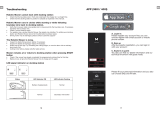
EasiLife App available for download on
AppStore and Google Play.
6. To change the settings
All settings for the robotic lawn mower are done via the menu functions. Please read the Opera-
tor’s manual and become familiar with the menus and settings.
1. The
Schedule
function is used to adjust the mowing time to suit your work area. If the robotic lawn
mower is allowed to mow too often, the grass may appear flattened. Use the scheduling wizard to
set a suitable schedule. Push the Menu button and select
Schedule > Wizard
and enter the size of
your work area. If you want to change the schedule settings for individual days use
Schedule >
Advanced
.
2. Use the Mode button to choose operating mode, for example
Main area
,
Secondary area
and
Park
.
3
1
2
21
QG_P01_Flymo_1141897-26.indd 4QG_P01_Flymo_1141897-26.indd 4 2019-11-18 16:25:032019-11-18 16:25:03
  • Page 1 1
  • Page 2 2
  • Page 3 3
  • Page 4 4

Flymo Flymo EasiLife 500 Quick start guide

Type
Quick start guide

Ask a question and I''ll find the answer in the document

Finding information in a document is now easier with AI