Page is loading ...

OWNER'S MANUAL
MODEL W1761/W1762
12" TABLE SAW WITH
RIVING KNIFE
Phone: (360) 734-3482 • Online Technical Support: tech-support@shopfox.biz
COPYRIGHT © SEPTEMBER, 2007 BY WOODSTOCK INTERNATIONAL, INC.
WARNING: NO PORTION OF THIS MANUAL MAY BE REPRODUCED IN ANY SHAPE OR FORM WITHOUT
THE WRITTEN APPROVAL OF WOODSTOCK INTERNATIONAL, INC.
Printed in Taiwan
#9077BL

Model W1761/W1762
12" Table Saw
Manual Update
(For Models Mfg. Before 1/10; Sold After 7/10)
Phone #: (360) 734-3482 • Online Tech Support: tech-support@shopfox.biz • Web: www.shopfox.biz
COPYRIGHT © AUGUST, 2008 BY WOODSTOCK INTERNATIONAL, INC.
WARNING: NO PORTION OF THIS MANUAL MAY BE REPRODUCED IN ANY SHAPE OR FORM WITHOUT
THE WRITTEN APPROVAL OF WOODSTOCK INTERNATIONAL, INC.
Printed in USA#13232BL
We made a few changes to this table saw since the manual was originally written. The saw you received
has a different blade guard with a clear shield, removable anti-kickback pawls, and a new mounting
block that makes blade guard and riving knife installation/removal and adjustments much easier. As
part of this change, the table saw is now equipped with a one-piece 1" arbor. This new arbor no longer
accepts blades with a
5
⁄8" arbor; thus, only blades with a 1" hole can be installed. (We apologize if this
change causes any inconvenience.) Aside from these items, all other content in the original manual
applies to your machine.
Before operating your new machine, you MUST read and understand this manual update AND the original
manual to reduce the risk of injury from improper use or setup. Since this update covers changes made
to the machine after the owner's manual was printed, you MUST keep this update with your owner's
manual for future reference.
If you have questions, contact our Technical Support at (360) 734-3482 or email
tech-support@shopfox.biz.
Inventory Differences
The inventory list shown in the original manual
will not exactly match what you receive with
your machine. Most notably, you will find a
different blade guard and you will not find the
5
⁄8" arbor insert.
Figure 1. Notable inventory differences you will
find when reviewing the inventory list in the
original manual.
Old
New
Important Changes to Assembly
The new guard spreader and riving knife have size
requirements for aftermarket blades that must be
met. These instructions are provided in following
pages in this update.
You can generally substitute the blade and blade
guard installation/adjustment instructions in this
update for those in the original manual.

-2-
Model W1761/W1762 (M-1/10, S7/10+)
The spreader/riving knife included with this machine
is 0.09" (2.3mm) thick and is designed for 12" diameter
blades only.
When choosing a standard blade, make sure the blade
size meets the requirements listed below. (This does not
apply to dado blades.) The thickness of the blade body
and teeth can be measured with calipers or any precision
measuring device.
Blade Size Requirements:
• Body Thickness: 0.074"–0.082"
(1.9mm–2.1mm)
• Kerf (Tooth) Thickness: 0.114"–0.122" (2.9mm–
3.1mm)
Blade Requirements
Figure 2. Loosening arbor nut.
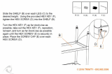
To install a new blade, do these steps:
1. DISCONNECT SAW FROM POWER!
2. Remove the table insert and blade guard/riving
knife, depending on what is installed.
3. Use the arbor wrenches to loosen and remove the
arbor nut, flange, and blade.
Note: The arbor nut has right hand threads; turn it
counterclockwise to loosen.
4. Slide the blade over the arbor with the teeth facing
the front of the saw, as shown in Figure 3.
5. Re-install the arbor flange and the arbor nut, then
tighten them against the blade with the wrenches
included with the saw, as shown in Figure
2. DO NOT
overtighten.
6. Re-install the blade guard/riving knife and the table
insert.
Blade Installation
Figure 3. Example of correct blade direc-
tion and blade components installation
order.

-3-
Model W1761/W1762 (M-1/10, S7/10+)
Blade Guard
This update provides all installation and adjustment infor-
mation relevant to the new blade guard. The term "blade
guard" refers to the assembly that consists of the clear
polycarbonate shield, the spreader, and the anti-kickback
pawls on each side of the spreader (see Figure 4).
Figure 4. Anatomy of the new blade guard
now supplied with the table saw.
Jgi\X[\i
:c\XiJ_`\c[
8ek`$B`ZbYXZbGXnc
Guard
The clear polycarbonate guard allows the operator to
see the blade cut the workpiece during operation. This
guard is designed to lift as the workpiece is pushed into
the blade and remain in contact with the workpiece
throughout the entire cut.
The guard reduces injury risk by providing a barrier
around the blade that helps prevent accidental contact
and contact from flying wood chips.
To ensure that the guard does its job effectively, it must
always be in the downward position against the table
during idle operation, and the hinge mechanism must be
maintained in good working condition so the guard can
freely pivot up and down to accommodate the height of
the workpiece and return to the table surface.
Spreader
The spreader is a metal plate that prevents the newly cut
kerf of the workpiece from pinching the backside of the
blade, causing kickback.
The spreader also acts as a barrier behind the blade to
shield hands from being pulled into the blade if kickback
occurs.

-4-
Model W1761/W1762 (M-1/10, S7/10+)
Installing Blade Guard & Spreader
1. DISCONNECT SAW FROM POWER!
2. Remove the table insert.
3. Insert the spreader into the bracket slot and tight-
en the lock knob shown in Figure 5 to secure the
spreader.
4. Tug the spreader up to verify it is locked.
5. Lift the blade guard cover just enough to slide the
table insert into the table slot over the blade, then
secure the insert with the screw at the front of the
insert.
The blade guard, when properly installed, should
look like Figure 6 and should pivot freely so it
touches the table surface in the down position. It
should also swing up high enough to accommodate
the workpiece.
6. Check to make sure the blade is 90° to the table.
Follow the instructions in the original manual for
setting the 90° stop bolt.
7. Swing one side of the blade guard up and out of the
way.
8. While lifting up on the right spreader pawl, place a
straightedge against the blade and the spreader.
When properly aligned, the spreader/riving knife
will be in the "Alignment Zone," (Figure 7) and will
be parallel with the blade.
Figure 5. Location to secure blade guard.
In order to work properly, the spreader or riving
knife cannot be bent or misaligned with the blade. If
either of these gets accidentally bent, DISCONNECT
SAW FROM POWER, and straighten or replace it.
Using a bent or misaligned spreader will increase
the risk of kickback! Refer to Page 8 to check/adjust
alignment if necessary.
Figure 7. Spreader/riving knife alignment
zone.
8c`^ed\ek
Qfe\
Jgi\X[\ifi
I`m`e^Be`]\
9cX[\
JkiX`^_k\[^\
Figure 6. Blade guard and insert installed.
Screw
Lock Knob

-5-
Model W1761/W1762 (M-1/10, S7/10+)
— If the spreader/riving knife is not inside the align-
ment zone and not parallel with the blade, then it
needs to be adjusted (refer to Page 8).
— If the spreader/riving knife is not parallel with
the blade, it may be bent. Proceed to "Checking
Alignment" on Page 8 to determine if the spread-
er/riving knife is bent.
Anti-Kickback Pawls
Anti-kickback pawls allow the workpiece to travel in only
one direction. If the workpiece moves backwards, such as
from kickback, the pawls will dig into the workpiece to
slow or stop it.
To work properly, the pawls must return to their bottom-
most position after pivoting, as shown in Figure 8.
Note: The right pawl is designed to tilt slightly away
from the blade guard assembly to prevent the pawl from
catching in the table insert.
If the pawls fail to return to the bottom position or parts
are binding, the pivot spring may have been dislodged or
broken and will need to be fixed/replaced.
Figure 8. Pawls in return position.
Pawl
Knob
We do not recommend removing the
pawls during normal operations unless
absolutely necessary. In most situa-
tions, removing the pawls will increase
your risk of serious personal injury in
the event of kickback.
Removing Pawls
You might remove the pawls if you are concerned
about them scratching a delicate workpiece, or if you
believe that they will obstruct a narrow workpiece and
cause feeding difficulty or loss of control. Use your
best judgment before removing the pawls, as they are
provided for your safety.
To remove the pawls, do these steps:
1. Loosen the knob on top of the spreader several
turns, then remove the blade guard assembly.
2. Press the button (Figure 9) on the block that holds
the pawls, then remove the pawls from the spreader.
3. Re-install the blade guard onto the spreader, making
sure the front and back pins on the blade guard slide
all the way into the spreader slots, then tighten the
top knob to secure the guard.
Figure 9. Button for removing pawls.
Pawl
Button

-6-
Model W1761/W1762 (M-1/10, S7/10+)
Re-installing Pawls
1. Loosen the knob on top of the spreader, then remove
the blade guard.
2. Slide the pin in the pawl block into the second
groove from the front of the spreader, as shown in
Figure 10.
3. Press the button on the pawl block shown in Figure
9, then pivot the pawls down until they lock into
place.
4. Re-install the blade guard onto the spreader and
secure with the top knob.
When to Use the Blade Guard
The blade guard assembly MUST always be installed on
the saw for all normal through cuts (those where the
blade cuts all the way through the thickness of the
workpiece).
When Not to Use the Blade Guard
The blade guard cannot be used for any non-through
cuts (those in which the blade does not cut all the way
through the thickness of the workpiece).
Sometimes the blade guard or its components can get in
the way when cutting very narrow workpieces or other
specialized cuts. Because the blade guard is provided to
decrease your risk of injury, it should not be used if it
gets in the way of making a safe cut. Use good judgment!
IMPORTANT: Whenever the blade guard cannot be used,
the riving knife must be installed.
Figure 10. Re-installing pawls.
Groove
Pin

-7-
Model W1761/W1762 (M-1/10, S7/10+)
Riving Knife
?\`^_k;`]]\i\eZ\
D`e`dld(dd
DXo`dld,dd
I`m`e^
Be`]\
Figure 11. Height difference between
riving knife and blade.
D`e`dld*dd
Kfg;`jkXeZ\
9fkkfd;`jkXeZ\
DXo`dld/dd
D`e`dld*dd
DXo`dld/dd
KXYc\
I`m`e^
Be`]\
Figure 12. Allowable top and bottom
distances between riving knife and blade.
The riving knife works in the same manner as the spreader
on the blade guard assembly. It is a metal plate that pre-
vents the newly cut workpiece from pinching the backside
of the blade and causing kickback.
The key difference between the spreader and the riving
knife is that the riving knife mounts below the blade's high-
est point of rotation, as shown in Figure 11.
The height difference between the riving knife and the
blade allows the workpiece to pass over the blade during
non-through cuts (those in which the blade does not cut all
the way through the thickness of the workpiece).
The riving knife acts as a barrier behind the blade to
reduce the risk of hands being pulled into the blade if
kickback occurs. The riving knife must be kept within the
range shown in Figure 12. For that reason, a 12" blade is
required for operations that use a riving knife.
When to Use the Riving Knife
Use the riving knife for all non-through cuts made with a
standard table saw blade (i.e., dadoes or rabbet cuts, and
when using a tenoning jig), or when using a 12" diameter
dado blade.
Also, use the riving knife for those special operations
where the blade guard or its components get in the way
of safe operation, such as with very narrow cuts.
When Not to Use the Riving Knife
Do not use the riving knife with a dado blade that has
a diameter smaller than 12" in diameter. Otherwise, the
riving knife height will exceed the blade height and the
workpiece will hit the riving knife during the cut, forcing
the operator into a dangerous situation of trying to turn
the saw off with the workpiece stuck halfway through the
cut.
In addition, although it is possible to use the riving knife
for through cutting operations, the blade guard assembly
offers far more injury protection and risk reduction than
the riving knife. Therefore, we strongly recommend that
you use the blade guard assembly instead of the riving
knife for through cuts.
Installing Riving Knife
The riving knife installs in a similar manner to the blade
guard and spreader. Refer to Blade Guard on Page 3 for
installation instructions.
To ensure that the riving knife works
safely, it MUST be aligned with and
correctly adjusted to the blade. Refer
to Page 8 to check or adjust the riving
knife alignment.

-8-
Model W1761/W1762 (M-1/10, S7/10+)
Figure 14. Spreader/riving knife alignment
zone.
8c`^ed\ek
Qfe\
Jgi\X[\ifi
I`m`e^Be`]\
9cX[\
JkiX`^_k\[^\
Spreader or Riving Knife
Alignment
Checking Alignment
The blade guard spreader and riving knife must be aligned
with the blade when installed. If the spreader/riving knife
is not aligned with the blade, then the workpiece will
before forced sideways during the cut, which will increase
the risk of kickback.
Tools Needed Qty
Straightedge .....................................................1
To check the spreader/riving knife alignment, do these
steps:
1. DISCONNECT SAW FROM POWER!
2. Raise the saw blade to the maximum height so you
have easy working access.
3. Check to make sure the blade is parallel with
the miter slot and is 90° to the table. Follow the
instructions in the original manual for checking miter
slot —blade parallelism, and for setting the 90° stop
bolt.
4. Place the straightedge against the top and bottom of
blade and spreader/riving knife, as shown in Figure
13. The spreader/riving knife should be parallel
with the blade along its length at both positions
and should be in the "Alignment Zone," as shown in
Figure 14.
— If the spreader/riving knife is not parallel with the
blade and inside the alignment zone, then it needs
to be adjusted. Proceed to Adjusting Alignment
instructions.
— If the spreader/riving knife is not parallel with the
blade at either the top or bottom, it may be bent.
Remove the spreader/riving knife and place it on
a flat surface and check to see if the spreader/
riving knife lays evenly along its length. If the
spreader/riving knife does not lay evenly, proceed
to Adjusting Bent Spreader/Riving Knife on Page
9.
Figure 13. Checking top and bottom riving
knife parallelism with blade.
Table
Riving
Knife
Top Alignment
Bottom Alignment

-9-
Model W1761/W1762 (M-1/10, S7/10+)
Figure 15. Set screws for adjusting
spreader/riving knife position.
Mounting Block
Kfg:fekifc
J`[\
:fekifc
J`[\
:fekifc
9fkkfd:fekifc
Adjusting Bent Spreader/Riving Knife
1. DISCONNECT SAW FROM POWER!
2. Bend the spreader or riving knife by hand while
installed, then follow Steps 1–4 in Checking
Alignment on Page 8 to determine if it is parallel
with the blade and inside the "Alignment Zone."
— If this does not work, remove it to straighten.
— If you cannot straighten it properly, replace it.
Figure 16. Lock knob location.
Lock Knob
Possible Tools Needed Qty
Hex Wrench 2.5mm .............................................1
Hex Wrench 3mm ...............................................1
To adjust the spreader/riving knife position, do these
steps:
1. DISCONNECT SAW FROM POWER!
2. Remove the table insert.
3. Loosen the two button head cap screws on the
mounting block, then adjust the set screws on the
block to move it in the necessary direction (see
"Mounting Block" inset in Figure 15).
4. Tighten the lock (see Figure 16), then re-install
the table insert.
5. Follow Checking Alignment, Steps 1–4, on Page 8.
— If the spreader/riving knife is in the alignment
zone, no additional steps are necessary.
— If the spreader/riving knife is still not in the align-
ment zone, continue adjusting the set screws on
the mounting block as necessary to correctly posi-
tion the spreader/riving knife.
6. Tighten the two button head cap screws on the
mounting block to secure the spreader/riving knife
adjustment.
Adjusting Alignment
The spreader/riving knife mounts to a block that can be
repositioned to correctly align the spreader/riving knife
to the blade. The mounting block adjusts by turning the
set screws in each corner of the block. Figure 15 shows
the set screws associated with controlling the mounting
block position. Before proceeding, verify blade-miter slot
parallelism, as specified in your original manual.

-10-
Model W1761/W1762 (M-1/10, S7/10+)
Zero clearance inserts reduce tearout and increase user
safety. These inserts can be customized to fit a specific
blade height or blade angle for the applicable cutting
operation.
Zero-clearance table inserts may be available for the
Model W1761/W1762 through your local Woodstock
International Inc. Dealer. If you do not have a dealer
in your area, a zero-clearance insert can be purchased
through an online dealer. Please call or e-mail Woodstock
International Inc. Customer Service to get a current listing
of dealers at:
1-800-840-8420 or at sales@woodstockint.com.
If you plan on using a dado blade with your saw, you need
to purchase an additional zero-clearance table insert for
the dado blade.
IM PO RTA N T: Zero-clearance inserts cut with a dado blade
should not be used later with a standard blade. Not only
will you lose the benefits of having zero clearance, the
large gaps around the blade could increase your risk of
injury. For this reason, we strongly recommend that you
have a dedicated table insert for each dado width.
D3697—Standard Zero-Clearance Insert
Optional Table Insert
NOTICE
Refer to the newest copy of the Woodstock
International, Inc. Catalog or http://www.shopfox.
biz for other safety accessories available for this
machine.

-11-
Model W1761/W1762 (M-1/10, S7/10+)
New Parts
(M)
*,0M)
**+/M)
*+/M)$(
+'0M)
*+/M)$*
*+/M)$+
*+/M)$,
*+/M)$-
*+/M)$.
*+/M)$/
*+/M)$0
*+/M)$('
*(
*)
*)
*)
**
**
**
*+
*,
*-
*-
*.
*/
*0
+'
+(
+)
+*
++
+,
+-
+.
+/
+0
,'
,(
,)
,*
,+
,,
,-
,.
,.
,/
REF PART # DESCRIPTION REF PART # DESCRIPTION
1V2 X1761001V2 BLADE GUARD ASSY UL987 V2.05.10 51 X1761051 SHAFT SPRING
31 X1761031 LEFT PLATE 52 XPEC07M E-CLIP 7MM
32 XPLN02M LOCK NUT M5-.8 53 X1761053 LEFT TORSION SPRING
33 XPFH01M FLAT HD SCR M5-.8 X 15 54 X1761054 RIGHT PAWL
34 X1761034 LEFT COVER 55 X1761055 PAWL SHAFT
35 X1761035 ROD CENTER PIN 56 X1761056 SPREADER
36 XPS19M PHLP HD SCR M5-.8 X 6 57 XPORP003 O-RING 2.8 X 1.9 P3
37 X1761037 KNOB BOLT 58 X1761058 AMPUTATION HAZARD LABEL
38 X1761038 MAIN BRACKET 348V2 X1761348V2 MOUNTING BRACKET ASSY V2.01.10
39 X1761039 LEFT BRACKET 348V2-1 X1761348V2-1 MOUNTING BRACKET BASE V2.01.10
40 X1761040 RIGHT BRACKET 348V2-2 XPCAP14M CAP SCREW M8-1.25 X 20
41 XPBHS24M BUTTON HD CAP SCR M4-.7 X 10 348V2-3 X1761348V2-3 COMPRESSION SPRING V2.01.10
42 X1761042 MOUNTING PIN 348V2-4 X1761348V2-4 LOCKING BOLT V2.01.10
43 X1761043 RIGHT COVER 348V2-5 X1761348V2-5 MOUNTING BRACKET PLATE V2.01.10
44 X1761044 RIGHT PLATE 348V2-6 XPBHS06M BUTTON HD CAP SCR M5-.8 X 12
45 X1761045 SNAP RING 5MM 348V2-7 XPLW01M LOCK WASHER 5MM
46 X1761046 LEFT PAWL 348V2-8 X1761348V2-8 HANDLE V2.01.10
47 X1761047 RIGHT TORSION SPRING 348V2-9 XPBHS16M BUTTON HD CAP SCR M5-.8 X 16
48 X1761048 PAWL MOUNTING BRACKET 348V2-10 X1761348V2-10 SET SCREW M3-.5 X 12
49 X1761049 MOUNTING BRACKET PIN 359V2 X1761359V2 1" ARBOR V2.01.10
50 X1761050 MOUNTING BRACKET SHAFT 409V2 X1761409V2 RIVING KNIFE V2.01.10

=^\]FjVa^inBVX]^cZhVcYIddah
LddYhidX`>ciZgcVi^dcVa!>cX#XVgg^Zhi]djhVcYhd[egdYjXihYZh^\cZY
idbZZii]ZcZZYhd[idYVnhlddYldg`ZghVcYbZiValdg`Zgh#
6h`ndjgYZVaZgVWdjii]ZhZ[^cZegdYjXih/


SET UPELECTRICAL
MAINTENANCE
SERVICE
PARTS
OPERATIONSSAFETYINTRODUCTION
USE THE QUICK GUIDE PAGE LABELS TO SEARCH OUT INFORMATION FAST!
INTRODUCTION .....................................2
Woodstock Technical Support .................. 2
W1761 Specifications ............................
3
W1762 Specifications ............................
4
Controls and Features ...........................
5
SAFETY ...............................................6
Standard Safety Instructions ...................
6
Additional Safety for Table Saws .............. 8
Preventing Kickback ............................. 9
Protecting Yourself from Kickback ...........
10
Common Terms ..................................
11
ELECTRICAL ....................................... 12
W1761 220V Single-Phase Operation ........
12
Extension Cords .................................
12
W1761 Electrical
Specifications ..............12
W1762 220V 3-Phase Operation ...............
13
W1762 440V 3-Phase Operation .............13
Phase Converter .................................
13
Electrical Spec
ifications .......................13
Rewiring to 440V ................................
13
SETUP .............................................. 14
Unpacking ........................................14
Items Needed for Set Up .......................
14
Inventory .........................................15
Cleaning Machine ................................17
Machine Placement .............................
17
Extension Table .................................
18
Saw Blade ........................................
21
Arbor ..............................................21
Table Insert ......................................
22
Blade Guard & Splitter .........................
22
Riving Knife ......................................
23
ON/OFF Switch ..................................
24
Miter Gauge ......................................
24
Fence Components ..............................
24
Dust Collection ..................................
25
Recommended Adjustments ...................
25
Test Run ..........................................
26
OPERATIONS ...................................... 27
General ...........................................27
Basic Controls ....................................
27
Disabling On/Off Switch .......................
28
Blade Selection ..................................
28
Workpiece Inspection ...........................
30
Non-Through & Through Cuts .................
30
Ripping ............................................31
Crosscutting ......................................32
Miter Cuts ........................................
33
Blade Tilt & Bevel Cuts ........................
33
Dado Cutting .....................................
34
Rabbet Cutting ..................................
36
Resawing ..........................................38
Table Saw Accessories ..........................41
MAINTENANCE .................................... 44
General ...........................................44
Cleaning ..........................................44
Lubrication .......................................44
SERVICE ............................................ 45
Troubleshooting .................................45
Replacing Flat Belt ..............................
47
Blade Tilt Stops ..................................
49
Digital Readout ..................................
50
Miter Slot to Blade Parallelism ...............
51
Blade Alignment .................................
52
Adjusting Fence .................................
53
Miter Gauge ......................................
54
W1761/W1762 Electrical Components .......55
W1761 Wiring Diagram .........................
56
W1762 Electrical Components ................57
W1762 Wiring Diagram 220V, 3-Phase .......
58
W1762 Wiring Diagram 440V, 3-Phase .......
59
PARTS .............................................. 60
Blade Guard Assembly ..........................60
Fence Assembly .................................61
Miter Gauge Assembly
.........................62
Main Table, Motor &
Cabinet ................63
Extension Table Assembly
....................66
Label Placement ................................
67
Contents

-2-
W1761/W1762 12" Table Saw with Riving Knife
INTRODUCTION
Woodstock Technical Support
This machine has been specially designed to provide many years of trouble-free service. Close attention
to detail, ruggedly built parts and a rigid quality control program assure safe and reliable operation.
Woodstock International, Inc. is committed to customer satisfaction. Our intent with this manual is to
include the basic information for safety, setup, operation, maintenance, and service of this product.
We stand behind our machines! In the event that questions arise about your machine, please contact
Woodstock International Technical Support at (360) 734-3482 or send e-mail to: tech-support@shopfox.
biz. Our knowledgeable staff will help you troubleshoot problems and process warranty claims.
INTRODUCTION
If you need the latest edition of this manual, you can download it from http://www.shopfox.biz.
If you have comments about this manual, please contact us at:
Woodstock International, Inc.
Attn: Technical Documentation Manager
P.O. Box 2309
Bellingham, WA 98227
Email: manuals@woodstockint.com

-3-
W1761/W1762 12" Table Saw with Riving Knife
INTRODUCTION

-4-
W1761/W1762 12" Table Saw with Riving Knife
INTRODUCTION

-5-
W1761/W1762 12" Table Saw with Riving Knife
INTRODUCTION
A
Controls and Features
A. ON/OFF Switch w/Emergency STOP Paddle
B. Front Rail
C. Miter Gauge
D. Blade Guard and Splitter
E. Fence Scale Indicator
F. Fence
G. Extension Table
H. Rear Rail
I. Fence Tube
J. Support Leg
K. Shelf End Plate
L. Lower Shelf
M. Arbor Wrenches
N. Blade Tilt Handwheel & Lock
O. Fence Lock Handle
P. Blade Angle Digital Readout
Q. Blade Tilt Scale
R. Blade Height Handwheel
S. Motor Cover
Figure 1. W1761/W1762 controls and features.
B
C
D
E
I
J
F
G
H
L
K
M
N
R
S
O
P
Q

-6-
W1761/W1762 12" Table Saw with Riving Knife
SAFETY
SAFETY
READ MANUAL BEFORE OPERATING MACHINE.
FAILURE TO FOLLOW INSTRUCTIONS BELOW WILL
RESULT IN PERSONAL INJURY.
Standard Safety Instructions
1. READ THROUGH THE ENTIRE MANUAL BEFORE STARTING MACHINERY. Machinery presents serious
injury hazards to untrained users.
2. MAKE SURE GUARDS ARE IN PLACE AND WORK CORRECTLY BEFORE USING MACHINERY.
3. ALWAYS USE ANSI APPROVED SAFETY GLASSES WHEN OPERATING MACHINERY. Everyday eye-
glasses only have impact resistant lenses—they are NOT safety glasses.
4. ALWAYS WEAR AN NIOSH APPROVED RESPIRATOR WHEN OPERATING MACHINERY THAT PRODUCES
DUST. Wood dust is a carcinogen and can cause cancer and severe respiratory illnesses.
5. ALWAYS USE HEARING PROTECTION WHEN OPERATING MACHINERY. Machinery noise can cause
permanent hearing damage.
6. WEAR PROPER APPAREL. DO NOT wear loose clothing, gloves, neckties, rings, or jewelry which may
get caught in moving parts. Wear protective hair covering to contain long hair and wear non-slip
footwear.
7. NEVER OPERATE MACHINERY WHEN TIRED, OR UNDER THE INFLUENCE OF DRUGS OR ALCOHOL.
Be mentally alert at all times when running machinery.
8. ONLY ALLOW TRAINED AND PROPERLY SUPERVISED PERSONNEL TO OPERATE MACHINERY. Make
sure operation instructions are safe and clearly understood.
9. KEEP CHILDREN AND VISITORS AWAY. Keep all children and visitors a safe distance from the work
area.
Indicates an imminently hazardous situation which, if not avoided, WILL
result in death or serious injury.
Indicates a potentially hazardous situation which, if not avoided, COULD
result in death or serious injury.
Indicates a potentially hazardous situation which, if not avoided, MAY
result in minor or moderate injury.
This symbol is used to alert the user to useful information about proper
operation of the equipment, and/or a situation that may cause damage
to the machinery.
NOTICE
/