Page is loading ...

MODEL T27709
500 lb. DUMP CART
INSTRUCTIONS
COPYRIGHT © MAY 2016 BY GRIZZLY INDUSTRIAL, INC.
WARNING: NO PORTION OF THIS MANUAL MAY BE REPRODUCED IN ANY SHAPE
OR FORM WITHOUT THE WRITTEN APPROVAL OF GRIZZLY INDUSTRIAL, INC.
(FOR MODELS MFD. SINCE 1/16) #JH18141 PRINTED IN CHINA
Specifications
Cart Size (L x W x H) ............ 59" x 30
1
⁄2" x 23
1
⁄2"
Overall Size (L x W x H) ........ 81" x 33
1
⁄2" x 38
1
⁄2"
Wheel Size (H x W) ................................. 16" x 5"
Total Load Capacity ................................ 500 lbs.
Net Weight ...............................................126 lbs.
SUFFOCATION HAZARD!
Immediately discard all plas-
tic bags and packing materi-
als to eliminate choking/suf-
focation hazards for children
and animals.
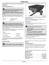
A. Right Panel ................................................. 1
B. Support Brace ............................................ 1
C. Wheels ....................................................... 2
D. Left Panel ................................................... 1
E. Corner Brackets ......................................... 2
F. Rear Panel.................................................. 1
G. Front Panel ................................................. 1
H. Axle ............................................................ 1
I. Rear Panel Assembly ................................. 1
J. Side Rails ................................................... 2
K. Bottom Panel .............................................. 1
L. Axle Supports ............................................. 2
M. Tongue ........................................................ 2
N. Hardware (Not shown)
—Phillips Head Screws M6-1 x 16 ............. 8
—Phillips Head Screws M8-1.25 x 16 ........ 8
—Cotter Pin 4 x 65mm ............................... 5
—Cotter Pin 11 x 128mm ........................... 8
—Lock Nut M6-1 ........................................ 8
—Lock Nut M8-1.25 ................................... 8
—Flat Washer 20mm ................................. 4
If any nonproprietary parts are missing (e.g. a
nut or a washer), we will gladly replace them; or
for the sake of expediency, replacements can be
obtained at your local hardware store. If you need
help with your new item, call our Tech Support at:
(570) 546-9663.
Figure 1. Inventory.
B
A
C
D
E
F
G
H
I
J
K
L
M
1) Never carry people or animals in cart.
2) Do not allow children to use unless
supervised by an adult.
3) Do not exceed 500 lb. load capacity.
4) Do not attempt to modify cart to increase
load capacity.
5) Do not over-inflate tires.
6) Do not allow cart to become top-heavy,
or it could fall over when pulling.
7) Do not park cart on an incline.
8) Do not use cart on roadways.
Inventory (Figure 1) Qty

-2-
T27709 500 Lb. Dump Cart (Mfd. 01/16)
Assembly
4. Attach wheels using (1) 20mm flat washer
on each side of wheel (see Figure 5), then
secure each wheel to axle with (1) cotter pin.
Turn cart upright.
To assemble cart:
1. Attach support brace to bottom panel using
(4) M6-1 x 16 Phillips head screws and (4)
M6-1 lock nuts, as shown in Figure 2.
Figure 2. Attaching support brace to bottom
panel.
2. Attach both axle supports to bottom panel
using (8) M8-1.25 x 16 Phillips head screws
and (8) M8-1.25 lock nuts, as shown in
Figure 3.
Note: Axle holes in axle supports should
align with one another above bottom panel.
Do not fully tighten axle support screws to
allow alignment of axle supports in next step.
Support
Brace
Bottom
Panel
3. Place tongue assembly onto both axle
supports and support brace, as shown in
Figure 4. Align axle support and tongue
assembly holes, and slide axle through. Fully
tighten screws from Step 2.
Figure 4. Attaching axle to tongue assembly and
axle supports.
Figure 5
. Connecting wheel to axle.
Tongue
Assembly
x 4
Axle
Support
Brace
Axle
Flat
Washer
x 2
Figure 3. Attaching axle supports to bottom
panel.
x 8
Axle
Support
(1 of 2)

T27709 500 Lb. Dump Cart (Mfd. 01/16)
-3-
5. Attach corner brackets to left and right side
panels using (4) M6-1 x 16 Phillips head
screws and (4) M6-1 lock nuts, as shown in
Figure 6.
6. Attach both left and right side panels to bot-
tom panel using three cotter pins per side
(see Figure 6).
Figure 6
. Corner brackets and side panels
installed on bed.
7. Connect front panel assembly using (4) cotter
pins, and use the front panel locks to connect
to each side panel, as shown in Figure 7.
8. Slide rear panel into corner brackets and
ensure rear panel pins go into holes in bottom
panel to secure rear panel (see Figure 8).
Figure 7
. Front panel installed.
Front
Panel
Lock
9. Insert front and side rails into rail brackets
(see Figure 9).
x 4
x 6
Side
Panel
Corner
Bracket
(1 of 2)
Figure 8. Connecting rear panel to side panels.
Rear
Panel
Corner
Bracket
Panel
Pins
Cotter
Pin
x 2
Figure 9. Inserting front and side rails.
Side
Rails
Front
Rail
Rail
Brackets

-4-
T27709 500 Lb. Dump Cart (Mfd. 01/16)
10. Insert cotter pin into plate behind release bar
on trailer tongue (see Figure 10).
Note: Pin prevents cart from pivoting up
and dumping its load. Remove pin to dump
contents.
Operation
The Model T27709 has a maximum capac-
ity of 500 lbs. and features a tilting dump bed
with removable rear panel for easy loading and
unloading.
The trailer attaches to a tow vehicle using a hitch
pin with cotter pin and is not rated for on-road
use.
Positioning roughly 60% of the trailer payload in
front (tongue end) of the axle will help maintain
better control and handling of the trailer while
moving. This also ensures payload will not cause
the trailer to pivot uncontrollably when the release
handle is pulled.
To tilt dump bed:
1. Position rear of trailer in correct location for
dumping contents.
2. Remove cotter pin from release plate, and
pull release bar with your hand (see Figure
11).
Note: Ensure trailer payload is properly posi-
tioned with majority of payload situated near
front (tongue end) of trailer.
Figure 10. Securing plate with cotter pin.
Release
Bar
Cotter
Pin
Plate
3. If needed, lift trailer bed to help dump payload.
4. Lower trailer bed back into horizontal posi-
tion, and re-insert cotter pin into release
plate.
Figure 11. Releasing dump bed.

T27709 500 Lb. Dump Cart (Mfd. 01/16)
-5-
Accessories
T21273—Golden Cowhide Gloves
T21272—Golden Pigskin Gloves
T20692—Deluxe Soft Goatskin Gloves
Grizzly offers a wide selection of synthetic and
leather gloves for all-day comfort in a variety of
working conditions.
Figure 12. Gloves.
T21272
T21273
T20692
H0605—All Steel Round Head Shovel
H0607—Wood Handle Square Head Shovel
The D-handle on the H0605 shovel makes trench-
ing or turning the garden soil an easy task. The
top edge of the shovel has a rolled edge to make
it easier to apply foot pressure for digging. The 14
gauge steel shovel head is swaged and welded
onto the steel handle, which is ribbed for strength.
Overall length is 38".
This 48
1
⁄2" long H0607 Wood Handle shovel pro-
vides extra reach and ergonomic advantage for
the taller user. The wooden handle is contoured
and is pinned to the head with a steel rivet to
avoid twisting. The 14 gauge steel shovel head
measures 9" wide by 11" deep with a rolled top
edge for a convenient foot hold.
Figure 14. Shovels.
H0607
H0605
Basic Eye Protection
T20451—“Kirova” Clear Safety Glasses
T20452—“Kirova” Anti-Reflective S. Glasses
H7194—Bifocal Safety Glasses 1.5
H7195—Bifocal Safety Glasses 2.0
H7196—Bifocal Safety Glasses 2.5
Figure
13. Assortment of basic eye protection.
T20451
T20452
H7194

-6-
T27709 500 Lb. Dump Cart (Mfd. 01/16)
1
2
3
4
5
6
7
8
9
10
12
13
14
15
16
17
18
19
2
6
20
21
24
26
27
28
29
30
31
32
36
34
35
37
38
39
27
27
27
36
38
32
16
36
30
37
15
24
27
grizzly.com
MODEL T27709
DUMP CART
Specifications
WARNING!
Mfd. for Grizzly in China
S/N
Date
To reduce risk of serious personal injury when using this machine:
1. Read and understand manual before using this machine.
2. DO NOT exceed cart weight limit of 250 lbs.
3. DO NOT tow cart on public roads or highways.
4. DO NOT exceed 10 mph. Reduce towing speed on rough terrain or hills.
5. Regularly inspect cart for worn or damaged parts.
6. Use cart only for designed purpose. DO NOT modify.
7. DO NOT use this cart to carry people; it is not a toy.
8. Always maintain tire pressure of 25 PSI.
9. Prevent unauthorized use by children; restrict access when unattended.
Maximum Capacity: 900 lbs.
Tire Pressure: 25 PSI.
Weight: 128 lbs.
41
40
27
27
37
33
22
23
42
27
16
11
REF PART # DESCRIPTION REF PART # DESCRIPTION
1 PT27709001 BOTTOM PANEL 22 PT27709022 HITCH PIN
2 PT27709002 WHEEL AXLE SUPPORT 23 PT27709023 HITCH PIN BRACKET
3 PT27709003 TONGUE 24 PT27709024 PANEL LATCH M8-1.25 X 20
4 PT27709004 LEFT PANEL 26 PT27709026 LATCH CAP PLASTIC
5 PT27709005 RIGHT PANEL 27 PT27709027 COTTER PIN 4 X 65 HAIR-PIN
6 PT27709006 SIDE RAIL 28 PT27709028 FLAT WASHER 6MM
7 PT27709007 FRONT PANEL 29 PT27709029 FLAT WASHER 8MM
8 PT27709008 FRONT RAIL 30 PT27709030 FLAT WASHER 20MM
9 PT27709009 TONGUE RELEASE PEDAL 31 PT27709031 PHLP HD SCR M6-1 X 16
10 PT27709010 REAR PANEL 32 PT27709032 PHLP HD SCR M4-.7 X 16
11 PT27709011 WHEEL ASSEMBLY 33 PT27709033 PHLP HD SCR M8-1.25 X 16
12 PT27709012 LEFT REAR BRACKET 34 PT27709034 HEX BOLT M8-1.25 X 20
13 PT27709013 RIGHT REAR BRACKET 35 PT27709035 HEX BOLT M6-1 X 95
14 PT27709014 WHEEL AXLE 36 PT27709036 LOCK NUT M8-1.25
15 PT27709015 RAIL CLAMP 37 PT27709037 LOCK NUT M6-1
16 PT27709016 GROMMET 18MM I.D. PLASTIC 38 PT27709038 LOCK NUT M4-.7
17 PT27709017 COTTER PIN 11 X 128 HAIR-PIN 39 PT27709039 HEX NUT M6-1
18 PT27709018 EXTENSION SPRING 2 X 14 X 140MM 40 PT27709040 GRIZZLY.COM LABEL
19 PT27709019 SPACER 35L METAL 41 PT27709041 MACHINE ID LABEL
20 PT27709020 COLLARED PIN M6-1 X 10, 38L 42 PT27709042 TOUCH-UP PAINT, GRIZZLY GREEN
21 PT27709021 TONGUE SUPPORT
T27709 Parts Breakdown & List
/