Page is loading ...

Copyright 2017
610-0082-01H DCN7785
Teledyne API
25 September 2017
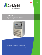
OG5000™ Ozone Generator
Model OG5000B-A
User Manual


Title: OG5000™ Ozone Generator, Model OG5000B-A
User Manual
610-0082-01H DCN7785 25 September 2017
Proprietary: The contents of this document are copyright
protected. ©2002-17 by Teledyne API.
Page 1
Contents
CONTENTS .................................................................................................................................................. 1
FIGURES ...................................................................................................................................................... 2
TABLES ........................................................................................................................................................ 2
1. GENERAL PRECAUTIONS ...................................................................................................................... 3
Safety ........................................................................................................................................................................ 5
Safety Label ............................................................................................................................................................. 5
2. OG5000™ DESCRIPTION ....................................................................................................................... 6
3. OG5000™ SPECIFICATIONS AND REQUIREMENTS ........................................................................... 7
4. INSTALLATION AND CONNECTIONS .................................................................................................. 10
Mounting ............................................................................................................................................................... 10
Water Connection ................................................................................................................................................. 10
Oxygen Connection ............................................................................................................................................... 10
Ozone Connection ................................................................................................................................................. 10
Power Connection ................................................................................................................................................. 11
Ground Connection .............................................................................................................................................. 12
5. OPERATION ........................................................................................................................................... 14
Local Mode ............................................................................................................................................................ 16
Remote Mode......................................................................................................................................................... 18
Faults ...................................................................................................................................................................... 20
6. MAINTENANCE ...................................................................................................................................... 21
7. TYPICAL PERFORMANCE DATA ......................................................................................................... 22
8. CONTACTING TAPI ............................................................................................................................... 23

Title: OG5000™ Ozone Generator, Model OG5000B-A
User Manual
610-0082-01H DCN7785 25 September 2017
Proprietary: The contents of this document are copyright
protected. ©2002-17 by Teledyne API.
Page 2
Figures
FIGURE 1: OZONE GENERATOR MODEL OG5000B-A, FRONT VIEW ................................................... 6
FIGURE 2: OZONE GENERATOR, MODEL OG5000B-A, MECHANICAL DIMENSIONS ........................ 9
FIGURE 3: REAR PANEL ......................................................................................................................... 13
FIGURE 4: FRONT PANEL ........................................................................................................................ 14
FIGURE 5. TYPICAL OZONE SYSTEM ..................................................................................................... 17
FIGURE 6: CONCENTRATION VS FLOW ................................................................................................ 22
FIGURE 7: CONCENTRATION VS POWER ............................................................................................ 22
Tables
Table 1. 240 VAC, 3
φ
Δ, 50/ 60 Hz OPERATION, MAINS VAC .................................. 11
Table 2. 208/240 VAC, 1
φ
, 50/60 Hz OPERATION, MAINS VAC ................................ 12
Table 3. Controls and Indicators, Front Panel ............................................................... 15
Table 4. OG5000™ Remote Interface Connector (DB – 25)......................................... 19

Title: OG5000™ Ozone Generator, Model OG5000B-A
User Manual
610-0082-01H DCN7785 25 September 2017
Proprietary: The contents of this document are copyright
protected. ©2002-17 by Teledyne API.
Page 3
1. General Precautions
WARNINGS:
1. Ozone (O
3
) is a toxic gas. High concentrations of ozone are dangerous and
harmful to humans. Take reasonable steps to avoid exposure. The current
maximum 8-hour exposure limit for ozone is 0.1 ppm (according to U.S.
OSHA).
2. Install appropriate safety monitoring equipment wherever high concentrations
of ozone are used. Teledyne API (TAPI) manufactures several ozone
monitors for workplace safety applications.
3. Materials in contact with high concentrations of ozone should be suitable for
such use. 316L Stainless, Teflon™, Chemraz™ and Kynar™ are
recommended.
4. When performing any maintenance to the unit, make sure all AC power is
disconnected from the unit.
5. Certain components may be hot to the touch. Please allow proper cooling
time before working with these components.
6. Never attempt to open ozone catalyst canisters (if supplied). The content of
the canisters can be hazardous if not handled properly.
7. Use only TAPI-recommended spare parts. Substitution parts could result in
damage to the equipment, may create hazardous conditions, and will void the
warranty.
CAUTIONS:
1. Read the operating manual before operating the unit.
2. Do not subject the unit to extreme physical or thermal shock.
3. Use care in handling the unit and any of its components.

Title: OG5000™ Ozone Generator, Model OG5000B-A
User Manual
610-0082-01H DCN7785 25 September 2017
Proprietary: The contents of this document are copyright
protected. ©2002-17 by Teledyne API.
Page 4
GENERAL NOTES
1. All trademarks, registered trademarks, brand names or product names
appearing in this document are the property of their respective owners and
are used herein for identification purposes only.
2. This document is Copyright Protected.
3. Teledyne API (TAPI) reserves the right to make changes to the product
covered in this manual to improve performance, reliability or
manufacturability. Make sure that this Manual is used with the original
Product it was shipped with.
4. Although every effort has been made to ensure accuracy of the information
contained in this manual, TAPI assumes no responsibility for inadvertent
errors. Contents of the manual are subject to change without notice.
5. TAPI assumes no responsibility for the use of any measuring schemes
described herein.
6. This product is not intended or recommended by TAPI
for use in (a) medical
therapy or physical therapy of any kind whether as a direct or adjunct part of
such therapy, including, without limitation, life support (i.e., critical medical)
applications or (b) any nuclear facility applications. TAPI will not knowingly
sell this product for use in such applications. Use of the IN USA-brand
product in connection with medical or like treatment cannot be reasonably
expected to produce accurate monitorings of therapy or treatment and may
cause failure of the life support device or significantly affect its safety or
effectiveness. Use by any direct purchaser or after-market purchaser in such
applications whether or not known to TAPI shall absolve TAPI of any
responsibility or liability to such purchaser (s) or to any person (s) subjected
to or affected by such use knowingly or unknowingly.
7. This product should only be used as specified by this manual. Any use other
than as specified may impair the safety features of the system.

Title: OG5000™ Ozone Generator, Model OG5000B-A
User Manual
610-0082-01H DCN7785 25 September 2017
Proprietary: The contents of this document are copyright
protected. ©2002-17 by Teledyne API.
Page 5
Safety
• Ozone (O3) is a toxic gas. High concentrations of ozone are dangerous
and harmful to humans. Take reasonable steps to avoid exposure. The
current maximum 8-hour exposure limit for ozone is 0.1 ppm (according to
U.S. OSHA).
• Install appropriate safety monitoring equipment wherever high
concentrations of ozone are used. TAPI manufactures several ozone
monitors for workplace safety applications.
• Materials in contact with high concentrations of ozone should be suitable
for such use. 316L Stainless, Teflon™, Chemraz™ and Kynar™ are
recommended.
• When performing any maintenance to the unit, make sure all AC power is
disconnected from the unit.
• Certain components may be hot to the touch. Please allow proper cooling
time before working with these components.
• Never attempt to open ozone catalyst canisters (if supplied). The content
of the canisters can be hazardous if not handled properly.
• Use only TAPI-recommended spare parts. Substitution parts could result
in damage to the equipment, may create hazardous conditions, and will
void the warranty.
• Use only stainless steel gasket for the VCR gas connections
• Ozone must be destroyed before it can be released to exhaust. TAPI
manufactures a complete line of ozone destruction equipment. Please
consult with us for your ozone destruction requirements.
Safety Label
• The safety-warning label is intended to warn the users about the toxicity
and danger of the ozone gas. Prior to operating the generator, ensure that
ozone detector is attached to the generator and is functional. Ensure that
all other safety-monitoring features are functional.

Title: OG5000™ Ozone Generator, Model OG5000B-A
User Manual
610-0082-01H DCN7785 25 September 2017
Proprietary: The contents of this document are copyright
protected. ©2002-17 by Teledyne API.
Page 6
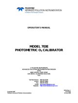
2. OG5000™ Description
The IN USA-brand OG5000™ ozone generator is designed to produce high purity
ozone gas. The ozone produced in the Model OG5000B-A comes from high purity
oxygen that is subjected to electrical discharge in the generating cells.
Adding small amounts of ‘doping’ or ‘spiking’ gas, such as N
2
or CO
2
, can increase
ozone output as well as stabilize the long-term ozone gas production.
% POWER
OZONE ON
STANDBY
LOCAL
REMOTE
SYSTEM FAULT
OVER VOLTAGE
EXT. INTERLOCK
INT. INTERLOCK
OZONE ON
OFF/ RESET
LOCAL
REMOTE
Figure 1: Ozone Generator Model OG5000B-A, Front View

Title: OG5000™ Ozone Generator, Model OG5000B-A
User Manual
610-0082-01H DCN7785 25 September 2017
Proprietary: The contents of this document are copyright
protected. ©2002-17 by Teledyne API.
Page 7
3. OG5000B-A Specifications and Requirements
Specifications
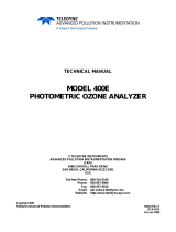
Dimensions (W x H x D)
19” x 10.5” x 18” (48 cm x 27 cm x 45 cm)
Oxygen Flow
0.5 to 20 slpm
Ozone Outlet Pressure
25 - 35 psig (Typically set to 30 psig)
Proof Pressure
80 psig
Ambient Temperature
5 – 35 °C
AC Power
208/240 VAC, 3φ, 50/60HZ
Dimensions (W x H x D)
19” x 10.5” x 18” (48 cm x 27 cm x 45 cm)
Weight
92 Lbs. (42 kg)
Facility Requirements
Gas Service
Oxygen
Spiking Gas (N
2
or CO
2
)
Inlet Pneumatic Port
Ozone Outlet Port
Grade 6 or better. (Less than 1 PPM water,
hydrocarbon and halocarbons.) See note below
about the use of LOX.
0.5% N
2
(Grade 5 or better) Or 8.0% CO
2
(Grade 5
or better) (% of total feed gas volume)
¼ “ VCR (male)
¼ “ VCR (male)
Cooling Water
Temperature:
Recommended Flow:
Minimum Flow:
Max Inlet Pressure:
Filtration:
Quality:
Resistivity:
Thermal Load:
Water Supply/Return Port
18 ºC ± 2ºC (keep water temperature above local
dew point)
2.5 GPM or more
2.0 GPM @ 18°C
60 PSIG
20 Microns or better (Customer Supplied)
Demineralized
0.5 mΩ/cm (minimum)
2.5 KW
¼” Compression (female)
Electrical Service
AC Power
Current
Breaker
208/240VAC, 50/60 Hz, 1φ, 2φ or 3φ
20 AMP RMS
30 Amp Breaker

Title: OG5000™ Ozone Generator, Model OG5000B-A
User Manual
610-0082-01H DCN7785 25 September 2017
Proprietary: The contents of this document are copyright
protected. ©2002-17 by Teledyne API.
Page 8
Warning on the Use of LOX (Liquid Oxygen):
Liquid Oxygen is a highly flammable liquid. Oxygen is the oxidizing agent in most
fires and Liquid Oxygen is extremely likely to cause combustion of any inflammable
material that it is in contact with.
When Liquid Oxygen (LOX) is used (evaporated) to feed the Ozone generators,
make sure that the LOX system is in good working condition and take special
precautions to prevent LOX from entering the Ozone Generator.
An MSDS can be obtained from the Internet at
‘www.uigi.com/MSDS_liquid_O2.html’.

Title: OG5000™ Ozone Generator, Model OG5000B-A
User Manual
610-0082-01H DCN7785 25 September 2017
Proprietary: The contents of this document are copyright
protected. ©2002-17 by Teledyne API.
Page 9
REMOTE
LOCAL
OFF/ RESET
OZONE ON
INT. INTERLOCK
EXT. INTERLOCK
OVER VOLTAGE
SYSTEM FAULT
REMOTE
LOCAL
STANDBY
OZONE ON
% POWER
TM
1.48
7.50
10.47
19.00
18.12
18.22
19.13
17.00
Figure 2: Ozone Generator, Model OG5000B-A, Mechanical Dimensions (inches).

Title: OG5000™ Ozone Generator, Model OG5000B-A
User Manual
610-0082-01H DCN7785 25 September 2017
Proprietary: The contents of this document are copyright
protected. ©2002-17 by Teledyne API.
Page 10
4. Installation and Connections
Mounting
The OG5000B-A is designed to be mounted in a standard 19” rack. Due to its
weight (82 lbs), support brackets are required. The hole pattern on the front panel
accepts ¼-20 or 6 mm hardware.
Water Connection
The Model OG5000B-A is cooled by re-circulating chilling water. Refer to the
Chilling Water Specification in Section 3.
Oxygen Connection
The Model OG5000B-A requires an Oxygen supply of Grade 6 or better. Less than
1-PPM water vapor, hydrocarbon and halocarbons. Connect the Oxygen gas supply
to the Model OG5000B-A via the ¼”female VCR pneumatic port identified as GAS
INLET.
IMPORTANT!!: Gas flow should be piped as indicated by the
labels on the rear panel of the generator.
Ozone Connection
The Model OG5000B-A produces ozone gas that is available at the GAS OUTLET
port. This is ¼” female VCR pneumatic connector.
IMPORTANT!!: Gas flow should be piped as indicated by the
labels on the rear panel of the generator.

Title: OG5000™ Ozone Generator, Model OG5000B-A
User Manual
610-0082-01H DCN7785 25 September 2017
Proprietary: The contents of this document are copyright
protected. ©2002-17 by Teledyne API.
Page 11
D
A
B
C
Power Connection
Operation from 208/240 VAC, 3
φ
Δ
, 50/ 60 Hz (Three Phase-Delta)
The Model OG5000B-A can operate from 240 VAC, 3 φ
Δ
, 50/ 60 Hz, at 20 Amp,
max. Use 12 AWG four-conductor cable terminated in a 4-pin circular style jack
connector to bring the mains VAC into the Model OG5000B-A. The following table
illustrates the pin-out of the circular jack connector.
Table 1. 240 VAC, 3 φ Δ, 50/ 60 Hz OPERATION, MAINS VAC
Pin #
Description
A
Ground (Earth)
B
Line 1
C
Line 2
D
Line 3
Note: Make sure that pin A (large Pin) is connected to Ground.
Note: Connect the three Lines to Pins B, C and D without regard to
sequence.
Use P/N 245-0223-01 (Amphenol p/n CA3106E18-13SB).
More information can be found at:
http://www.ittcannon.com/media/pdf/catalogs/ms_e.pdf
Operation from 208/240VAC 1
φ
, 50/60 Hz (Single Phase)
The Model OG5000B-A can operate from 208/240 VAC, 1 φ, 50/60 Hz, at 20 Amp,
RMS. Use 12 AWG three-conductor cable terminated in a 3-pin circular style jack
connector to bring the mains VAC in to the Model OG5000B-A. The following
table illustrates the pin-out of the circular jack connector.

Title: OG5000™ Ozone Generator, Model OG5000B-A
User Manual
610-0082-01H DCN7785 25 September 2017
Proprietary: The contents of this document are copyright
protected. ©2002-17 by Teledyne API.
Page 12
Table 2. 208/240 VAC, 1 φ, 50/60 Hz OPERATION, MAINS VAC
Pin #
Description
A
Line 1
B
Line 2 or Neutral
C
GROUND
Make sure that pin C is connected to Ground.
Use P/N 245-0204-01 (Amphenol p/n 97-3106A-16-10S)
More information can be found at:
http://www.ittcannon.com/media/pdf/catalogs/ms_e.pdf
Ground Connection
The Model OG5000B-A features a threaded stud, labeled “GROUND” located in the rear
panel, intended to allow for the connection, via a cable, between earth ground and the
chassis. Use 14 gauge wire (green and yellow) to connect to earth ground to chassis.
WARNING!!:
High voltages that can cause injury or death to operators are present in
the Model OG5000B-A.
The Model OG5000B-A must be grounded before operation. Do not
rely on the ground in the power cord, which can be removed.

Title: OG5000™ Ozone Generator, Model OG5000B-A
User Manual
610-0082-01H DCN7785 25 September 2017
Proprietary: The contents of this document are copyright
protected. ©2002-17 by Teledyne API.
Page 13
A
B
REMOTE INTERFACE
10 AMPS
208/240 VAC, 50/60 HZ
POWER IN
GAS INLET
GAS OUTLET
CHILLED WATER INLET
CHILLED WATER OUTLET
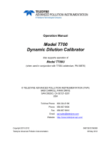
Figure 3: Rear Panel
The rear panel consists of:
• Two Electrical Connectors as follows:
o Main power input,
o DB-25 electrical connector for remote operation,
• Two Chilling Water Connectors as follows:
o Chilled Water Inlet Port
o Chilled Water Outlet Port
• Two Gas Ports as follows:
o Gas Inlet Port (Oxygen)
o Gas Outlet Port (Ozone)

Title: OG5000™ Ozone Generator, Model OG5000B-A
User Manual
610-0082-01H DCN7785 25 September 2017
Proprietary: The contents of this document are copyright
protected. ©2002-17 by Teledyne API.
Page 14
5. Operation
The Model OG5000B-A can be operated locally, via the controls located in the Front Panel;
or remotely, via the Remote Interface Connector (DB-25), located in the Rear Panel.
Refer to Figure 4, Model OG5000B-A: Front Panel, for location and identification of controls
and indicators.
% POWER
OZONE ON
STANDBY
LOCAL
REMOTE
SYSTEM FAULT
OVER VOLTAGE
EXT. INTERLOCK
INT. INTERLOCK
OZONE ON
OFF/ RESET
LOCAL
REMOTE
Figure 4: Front Panel

Title: OG5000™ Ozone Generator, Model OG5000B-A
User Manual
610-0082-01H DCN7785 25 September 2017
Proprietary: The contents of this document are copyright
protected. ©2002-17 by Teledyne API.
Page 15
Table 3.
below identifies Controls, Indicators and required External Signals
Table 3. Controls and Indicators, Front Panel
Identifier
Description
POWER BREAKER
SWITCH
This breaker is used to switch the AC power to the unit. When the
switch is in the ON position (breaker UP) the main AC power is applied
to the unit. When the switch is in the OFF position (breaker down) no
AC power is present.
OZONE ON – OFF/RESET
SWITCH
When the switch is set to the OZONE ON position the control
electronics will attempt to deliver the set-point power to the generating
cells
(1)
. When the switch is set to the OFF/RESET position, the control
electronics will remove power from the generating cells
LOCAL – REMOTE
SWITCH
In the LOCAL position it selects Local operation from the Front Panel
Controls, in the REMOTE position it selects remote-controlled
operation via the connector located in the Rear Panel
SET POINT KNOB
This knob controls the amount of power delivered to the generating
cells (and ultimately the amount of ozone being generated)
OZONE ON LED
This indicator is ON when power is applied to the generating cells, and
no alarm conditions are present
STANDBY LED
This indicator is ON when the generator is ready to make ozone and
there is no alarm condition detected
LOCAL LED
This indicator is ON when the Local Mode of Operation has been
selected
REMOTE LED
This indicator is ON when the Remote Mode of Operation has been
selected.
SYSTEM FAULT LED
This indicator is ON when the control electronics detects an over-
temperature condition in either the High Voltage Power Supply’s
switching transistors; the power magnetics components; or the
generating cells. The control electronics shuts off the HVPS and the
unit remains in this state until a reset
(2)
signal is detected
OVERVOLTAGE LED
This indicator is ON when an over-voltage condition is detected at the
high voltage power supply (HVPS). The control electronics shuts off
the HVPS and the unit remains in this state until a reset
(2)
signal is
detected
EXT. INTERLOCK LED
This indicator is ON when the EXT. INTERLOCK signal (Pin #12 in the
REMOTE-INTERFACE CONNECTOR) is HIGH.
INT.INTERLOCK LED
This indicator is ON when the control electronics detects that there is
not enough chilled water flow.
Notes:
(1) The attempt will be successful only if all alarms signals are off and the unit is set to operate on Local Mode.
(2) A Reset signal occurs when the “OZONE ON – OFF/RESET” switch is toggled, or the “REMOTE ON” signal
(Pin# 2 in the REMOTE-CONTROL CONNECTOR) is brought to a High (24 VDC) level. Refer to Table 4 for
a detailed pin-out and functionality of the Remote-Interface Connector

Title: OG5000™ Ozone Generator, Model OG5000B-A
User Manual
610-0082-01H DCN7785 25 September 2017
Proprietary: The contents of this document are copyright
protected. ©2002-17 by Teledyne API.
Page 16
Local Mode
In this mode, the front panel, (refer to Figure 4) is used to control the operation of the
generator.
IMPORTANT!!: Feed Gas flow should be established before
attempting to generate ozone.
IMPORTANT!!: Cooling water flow should be established before
attempting to generate ozone.
Typically, the Ozone Generator is installed as part of an “Ozone System”. Refer to Figure
5, “Typical Ozone System”. The following is a list of pre-operation requirements that need to
take place before Local Operation can start.
• Supply 24 VDC to the Remote Interface Connector. Use pin#1 for 24 VDC, and pin #7
for 24 VDC RETURN. (Refer to Table 4 for a complete pin-out description of the Remote
Control Connector).
• Place a jumper between pin#12 and pin#7 in the Remote Interface Connector. This will
enable the “External Interlock”. A Dry Contact (relay) can be used to replace the
electrical jumper. (Refer to
Table 4 for a complete pin-out description of the Remote
Control Connector).
• Verify that the cooling water connections are in place and that cooling water is flowing in
accordance with the unit’s requirements as specified in this manual.
• Verify that the Oxygen gas feed connection is in place.
• Turn on the flow of Oxygen feed
• Adjust the Back Pressure Regulator (BPR) to 30 psig.
• Set the “% POWER” knob fully counter clockwise
• Set the “LOCAL/REMOTE” toggle switch to the “LOCAL” position.
• The “LOCAL” Led Indicator should light
• Set the “OZONE ON/OFF-RESET toggle switch to the ” OFF-RESET” position
• Set the Power Breaker to the “ON” position

Title: OG5000™ Ozone Generator, Model OG5000B-A
User Manual
610-0082-01H DCN7785 25 September 2017
Proprietary: The contents of this document are copyright
protected. ©2002-17 by Teledyne API.
Page 17
• The “STANDBY” indicator should light
• Set the “OZONE ON/OFF-RESET toggle switch to the “ OZONE ON” position
• The “OZONE ON ” indicator should light and the “STANDBY” indicator should be off
• The “% POWER” digital readout should read 00
• Rotate the “% POWER” knob clockwise. This will apply increasingly larger voltage
across the generating cells, creating discharge and generating ozone.
NOTE: Ozone is toxic. Make sure that it exhausted through the proper equipment or it is
safely destroyed.
Figure 5. Typical Ozone System

Title: OG5000™ Ozone Generator, Model OG5000B-A
User Manual
610-0082-01H DCN7785 25 September 2017
Proprietary: The contents of this document are copyright
protected. ©2002-17 by Teledyne API.
Page 18
Remote Mode
The ozone generator can be operated from a remote control device. In this mode, an
external Analog Voltage, 0 to 10 VDC signal, controls the power delivered to the ozone
generating cells (ultimately controlling the amount of ozone produced).
10 VDC corresponds to 100% Power. The analog voltage signal is generated by an external
peripheral, and it is applied into the generator via the “Remote Interface Connector”, a DB-
25 electrical connector located in the rear panel. The following is a list of pre-operation
requirements that need to take place before Remote Operation can start.
• Supply 24 VDC to the Remote Interface Connector. Use pin#1 for 24 VDC, and pin #7
for 24 VDC RETURN. (Refer to Table 4 for a complete pin-out description of the Remote
Control Connector).
• Place a jumper between pin#12 and pin#7 in the Remote Interface Connector. This will
enable the “External Interlock”. A Dry Contact (relay) can be used to replace the
electrical jumper. (Refer to Table 4 for a complete pin-out description of the Remote
Control Connector).
• Verify that the cooling water connections are in place and that cooling water is flowing in
accordance with the unit’s requirements as specified in this manual.
• Verify that the Oxygen gas feed connection is in place.
• Turn on the flow of Oxygen feed
• Adjust the Back Pressure Regulator (BPR) to 30 psig.
• Set the “LOCAL/REMOTE” front panel toggle switch to the “REMOTE” position. This will
disable the “OZONE ON – OFF/RESET” switch located in the Front Panel, and that
function will be implemented via the REMOTE IN signal (PIN #2 in the Remote Interface
Connector.)
• Set the “OZONE ON/OFF-RESET toggle switch to the ” OFF-RESET” position
• Set the Power Breaker to the “ON” position
• The “STANDBY” indicator should light
• The “REMOTE” Led Indicator should light.
/