Page is loading ...

Owner’s Manual
60 Hz Air-Cooled Generators
15 kW EcoGen™
SAVE THIS MANUAL FOR FUTURE REFERENCE
Para español , visita: http://www.generac.com/service-support/product-support-lookup
Pour le français, visiter : http://www.generac.com/service-support/product-support-lookup
000918
Register your Generac product at:
WWW.GENERAC.COM
1-888-GENERAC
(888-436-3722)
(000209a)
WARNING
This product is not intended to be used in
a critical life support application. Failure to
adhere to this warning could result in
death or serious injury.

ii Owner’s Manual for 60 Hz Air-cooled Generators
Use this page to record important information about your generator set.
Record the information found on your unit data label on this
page. For the location of the unit data label, see Component
Locations. The unit has a label plate affixed to the inside
partition, to the left of the control panel console as shown in
Component Locations For directions on how to open the
top lid and remove the front panel, see Operation.
When contacting an Independent Authorized Service Dealer
about parts and service, always supply the complete model
number and serial number of the unit.
Operation and Maintenance: Proper maintenance and care
of the generator ensures a minimum number of problems
and keeps operating expenses at a minimum. It is the
operator’s responsibility to perform all safety checks, to
make sure that all maintenance for safe operation is
performed promptly, and to have the equipment checked
periodically by an Independent Authorized Service Dealer.
Normal maintenance, service and replacement of parts are
the responsibility of the owner/operator and, as such, are not
considered defects in materials or workmanship within the
terms of the warranty. Individual operating habits and usage
may contribute to the need for additional maintenance or
service.
When the generator requires servicing or repairs, Generac
recommends contacting an Independent Authorized Service
Dealer for assistance. Authorized service technicians are
factory-trained and are capable of handling all service
needs.To locate the nearest Independent Authorized Service
Dealer, please visit the dealer locator at:
www.generac.com/Service/DealerLocator/.
Model:
Serial:
Prod Date Week:
Volts:
LPV Amps:
NG Amps:
Hz:
Phase:
Controller P/N:
(000005)
WARNING
California Proposition 65. This product contains or
emits chemicals known to the state of California to
cause cancer, birth defects, and other reproductive
harm.
(000004)
WARNING
California Proposition 65. Engine exhaust and some
of its constituents are known to the state of California
to cause cancer, birth defects, and other reproductive
harm.

Owner’s Manual for 60 Hz EcoGen™ Generator iii
Section 1: Safety Rules & General
Information
Introduction ..........................................................1
Read This Manual Thoroughly ....................................1
How to Obtain Service .................................................1
Safety Rules .........................................................2
General Hazards .........................................................2
Exhaust Hazards .........................................................3
Electrical Hazards .......................................................3
Fire Hazards ................................................................4
Explosion Hazards ......................................................4
Section 2: General Information
EcoGen Operating Principle ...............................5
Benefits .......................................................................5
How It Works ...............................................................5
Startup .........................................................................5
Normal Running ..........................................................5
Small Load Changes ...................................................5
Large Load (Not Overload) ..........................................5
Automatic Voltage Regulator (AVR) Cooling Fans ......5
The Generator ......................................................6
Generator ....................................................................7
Engine .........................................................................7
Protection Systems .............................................8
Emission Information ..........................................8
Fuel Requirements ..............................................8
Battery Requirements .........................................8
Battery Charger ....................................................8
Engine Oil Requirements ....................................8
Section 3: Operation
Site Prep Verification .........................................11
Side Compartment .............................................11
Main Circuit Breaker (Generator Disconnect) ............11
LED Indicator Lights ..................................................11
120V GFCI Outlet/15 Amp Breaker ...........................11
Generator Enclosure .........................................11
Control Panel Interface .....................................13
Using the Auto/Off/Manual Interface Menu ....13
Menu Navigation ................................................14
Change Time and Date ...................................... 14
Programmable Timers ...................................... 14
Dealer Programmable ...............................................14
High Run Speed Timer ................................................... 14
USB Port for Firmware Updates ....................... 14
Battery Charger ................................................. 17
Manual Transfer Operation ............................... 17
Transfer to Generator Power Source ........................17
Transfer Back to Utility Power Source .......................17
Automatic Transfer Operation ......................... 18
Automatic Sequence of Operation .................. 18
Utility Failure ..............................................................18
Cranking ....................................................................18
Cold Smart Start ........................................................18
Load Transfer ............................................................18
Shutting Generator Down While Under Load . 18
To turn the generator OFF: .......................................18
To turn the generator ON: .........................................18
Section 4: Maintenance
Performing Scheduled Maintenance ............... 19
Check Enclosure Louvers ................................ 20
Check Lines and Connections ......................... 20
Checking Engine Oil Level ............................... 21
Engine Oil Recommendations ...................................21
Changing the Oil and Oil Filter ......................... 22
EcoGen Oil System Drain Pump Kit Parts List ..........22
EcoGen Oil System Drain Pump Assembly ..............22
EcoGen Oil Change Procedure .................................23
Replacing the Engine Air Filter ........................ 24
Replacing the AVR Filter .................................. 24
Maintaining the Spark Plugs ............................ 25
Valve Clearance Adjustment ............................ 25
Check Valve Clearance .............................................25
Adjust Valve Clearance .............................................25
Battery Maintenance ......................................... 26
Attention After Submersion ............................. 27
Corrosion Protection ........................................ 27
Table of Contents

Section 1:
iv Owner’s Manual for 60 Hz EcoGen™ Generator
Remove From / To Service Procedure .............27
Remove From Service .............................................. 27
Return to Service ...................................................... 27
Section 5: Troubleshooting / Diagnostics
Engine Troubleshooting ...................................29
Generator Troubleshooting ..............................30
G-Flex™ Troubleshooting .................................32
G-Flex™ Diagnostics .........................................34
Section 6: Installation Diagrams
Installation Drawing............................................35
Off Grid Mode Application Schematic .............36
Oil Make Up System Schematic .......................37

Safety Rules & General Information
Owner’s Manual for 60 Hz EcoGen™ Generator 1
Section 1: Safety Rules & General Information
Introduction
Thank you for purchasing this compact, high
performance, air-cooled, engine-driven generator. It is
designed to automatically supply electrical power to
operate critical loads during a normal power source
failure.
As supplied from the factory, this generator is designed to
work in off-grid applications.
In off-grid applications as a part of an alternative energy
system, the generator starts when the inverter/battery
charger detects the normal power source voltage has
dropped below a preset level. The generator powers the
inverter, and once the voltage level of the normal power
source rises to an acceptable level, the generator is shut
down. Another off-grid application would be for use in
remote locations such as for pumping water for a village
or campground, or for livestock.
The unit is factory installed in an all-weather metal
enclosure and is intended for outdoor installation only.
The generator can be operated using either natural gas
(NG) or vapor withdrawn liquid propane (LP).
NOTE: When sized properly, this generator is suitable for
supplying typical residential loads such as induction
motors (sump pumps, refrigerators, air conditioners,
furnaces, etc.), electronic components (computer,
monitor, TV, etc.), lighting loads and microwaves.
Read This Manual Thoroughly
If any portion of this manual is not understood, contact
the nearest Independent Authorized Service Dealer for
starting, operating and servicing procedures.
This manual must be used in conjunction with the
appropriate Installation Manual.
SAVE THESE INSTRUCTIONS: The manufacturer
suggests that this manual and the rules for safe operation
be copied and posted near the unit installation site.
Safety should be stressed to all operators and potential
operators of this equipment.
Throughout this publication and on tags and decals
affixed to the generator, DANGER, WARNING, and
CAUTION blocks are used to alert personnel to special
instructions about a particular operation that may be
hazardous if performed incorrectly or carelessly. Observe
them carefully. Their definitions are as follows:
NOTE: Notes provide additional information important to
a procedure or component.
These safety warnings cannot eliminate the hazards they
indicate. Observing safety precautions and strict
compliance with the special instructions while performing
the action or service are essential to preventing accidents.
The operator is responsible for proper and safe use of
the equipment. The manufacturer strongly recommends
that if the operator is also the owner, to read the Owner’s
Manual and thoroughly understand all instructions before
using this equipment. The manufacturer also strongly
recommends instructing other users to properly start and
operate the unit. This prepares them if they need to
operate the equipment in an emergency.
How to Obtain Service
When the generator requires servicing or repairs, contact
an Independent Authorized Service Dealer for assistance.
Service technicians are factory-trained and are capable of
handling all service needs. For assistance locating a
dealer, go to
www.generac.com/Service/DealerLocator/.
When contacting a dealer about parts and service,
always supply the complete model number and serial
number of the unit as given on its data decal, which is
located on the generator. Refer to Figure 2-1 for decal
location. Record the model number and serial numbers in
the spaces provided on the inside front cover of this
manual.
(000100a)
WARNING
Consult Manual. Read and understand manual
completely before using product. Failure to
completely understand manual and product
could result in death or serious injury.
(000001)
DANGER
Indicates a hazardous situation which, if not avoided,
will result in death or serious injury.
(000002)
WARNING
Indicates a hazardous situation which, if not avoided,
could result in death or serious injury.
(000003)
CAUTION
Indicates a hazardous situation which, if not avoided,
could result in minor or moderate injury.

Safety Rules & General Information
2 Owner’s Manual for 60 Hz EcoGen™ Generator
Safety Rules
Study these SAFETY RULES carefully before installing,
operating or servicing this equipment. Become familiar
with this Owner’s Manual and with the unit. The
generator can operate safely, efficiently and reliably only
if it is properly installed, operated and maintained. Many
accidents are caused by failing to follow simple and
fundamental rules or precautions.
The manufacturer cannot anticipate every possible
circumstance that might involve a hazard. The warnings in
this manual and on tags and decals affixed to the unit are,
therefore, not all-inclusive. If using a procedure, work
method, or operating technique the manufacturer does not
specifically recommend, verify that it is safe for others.
Also, make sure the procedure, work method or operating
technique utilized does not render the generator unsafe.
General Hazards
(000190)
DANGER
Loss of life. Property damage. Installation must always
comply with applicable codes, standards, laws and
regulations. Failure to do so will result in death
or serious injury.
Automatic start-up. Disconnect normal power source
and render unit inoperable before working on unit.
Failure to do so will result in death or serious injury.
(000236)
DANGER
(000209a)
WARNING
This product is not intended to be used in
a critical life support application. Failure to
adhere to this warning could result in
death or serious injury.
WARNING
This unit is not intended for use as a prime power
source. It is intended for use as an intermediate power
supply in the event of temporary power outage only.
See individual unit specifications for required
maintenance and run times pertaining to use.
(000247)
(000187)
WARNING
(000130)
WARNING
Accidental Start-up. Disconnect the negative battery
cable, then the positive battery cable when working
on unit. Failure to do so could result in death
or serious injury.
(000182)
WARNING
(000155)
WARNING
Only a trained and licensed electrician should perform
wiring and connections to unit. Failure to follow proper
installation requirements could result in death, serious
injury, and damage to equipment or property.
(000115)
WARNING
Moving Parts. Do not wear jewelry when
starting or operating this product. Wearing
jewelry while starting or operating this product
could result in death or serious injury.
(000111)
WARNING
Moving Parts. Keep clothing, hair, and
appendages away from moving parts. Failure
to do so could result in death or serious injury.
(000108)
WARNING
Hot Surfaces. When operating machine, do not
touch hot surfaces. Keep machine away from
combustibles during use. Hot surfaces
could result in severe burns or fire.
WARNING
Injury and equipment damage. Do not use
generator as a step. Doing so could result in falling,
damaged parts, unsafe equipment operation,
and could result in death or serious injury.
(000216)
(000146)
WARNING
Equipment and property damage. Do not alter
construction of, installation, or block ventilation for
generator. Failure to do so could result in unsafe
operation or damage to the generator.

Safety Rules & General Information
Owner’s Manual for 60 Hz EcoGen™ Generator 3
Inspect the generator regularly, and contact the nearest
Independent Authorized Service Dealer for parts needing
repair or replacement.
Exhaust Hazards
•
Adequate, unobstructed flow of cooling and
ventilating air is critical to correct generator
operation. Do not alter the installation or permit
even partial blockage of ventilation provisions, as
this can seriously affect safe operation of the
generator. The generator must be installed and
operated outdoors only.
Electrical Hazards
WARNING
Risk of injury. Do not operate or service this
machine if not fully alert. Fatigue can impair the
ability to service this equipment and could result
in death or serious injury.
(000215)
WARNING
Environmental Hazard. Always recycle batteries at an
official recycling center in accordance with all local
laws and regulations. Failure to do so could result in
environmental damage, death or serious injury.
(000228)
Asphyxiation. Running engines produce
carbon monoxide, a colorless, odorless,
poisonous gas. Carbon monoxide, if not
avoided, will result in death or serious injury.
(000103)
DANGER
(000178a)
Asphyxiation. Always use a battery operated carbon
monoxide alarm indoors and installed according to
the manufacturer’s instructions. Failure to do so
could result in death or serious injury.
WARNING
(000144)
DANGER
Electrocution. Contact with bare wires,
terminals, and connections while generator
is running will result in death or serious injury.
(000150)
DANGER
Electrocution. Never connect this unit to the electrical
system of any building unless a licensed electrician
has installed an approved transfer switch. Failure to
do so will result in death or serious injury.
(000237)
DANGER
Electrical backfeed. Use only approved switchgear to
isolate generator from the normal power source.
Failure to do so will result in death, serious injury,
and equipment damage.
(000152)
DANGER
Electrocution. Verify electrical system is
properly grounded before applying power.
Failure to do so will result in death or serious
injury.
(000188)
DANGER
Electrocution. Do not wear jewelry while
working on this equipment. Doing so will
result in death or serious injury.
(000104)
DANGER
Electrocution. Water contact with a power
source, if not avoided, will result in death
or serious injury.
(000144)
DANGER
Electrocution. Contact with bare wires,
terminals, and connections while generator
is running will result in death or serious injury.
(000145)
DANGER
Electrocution. In the event of electrical accident,
immediately shut power OFF. Use non-conductive
implements to free victim from live conductor. Apply
first aid and get medical help. Failure to do so will
result in death or serious injury.

Safety Rules & General Information
4 Owner’s Manual for 60 Hz EcoGen™ Generator
Fire Hazards
Comply with regulations the Occupational Safety and
Health Administration (OSHA) has established. Also,
verify that the generator is installed in accordance with
the manufacturer’s instructions and recommendations.
Following proper installation, do nothing that might alter a
safe installation and render the unit in noncompliance
with the aforementioned codes, standards, laws and
regulations.
Explosion Hazards
WARNING
Fire hazard. Do not obstruct cooling and
ventilating airflow around the generator. Inadequate
ventilation could result in fire hazard, possible
equipment damage, death or serious injury.
(000217)
WARNING
Fire and explosion. Installation must comply
with all local, state, and national electrical
(000218)
building codes. Noncompliance could result in unsafe
operation, equipment damage, death or serious injury.
WARNING
Fire hazard. Use only fully-charged fire
(000219)
extinguishers rated “ABC” by the NFPA. Discharged or
improperly rated fire extinguishers will not extinguish
electrical fires in automatic standby generators.
(000100a)
WARNING
Consult Manual. Read and understand manual
completely before using product. Failure to
completely understand manual and product
could result in death or serious injury.
WARNING
required safety equipment could result in
death or serious injury.
(000221)
Risk of electrocution. Refer to NFPA 70E for
safety equipment required when working with
with a live electrical system. Failure to use
(000147)
WARNING
Risk of Fire. Unit must be positioned in a
manner that prevents combustible material
accumulation underneath. Failure to do so
could result in death or serious injury.
(000192)
DANGER
(000151)
DANGER
Connection of fuel source must be done by a qualified
professional technician or contractor. Incorrect installation
of this unit will result in death, serious injury, and damage
to equipment and property damage.
(000174)
DANGER
Risk of fire. Allow fuel spills to completely dry
before starting engine. Failure to do so will
result in death or serious injury.
(000110)
WARNING
Risk of Fire. Hot surfaces could ignite
combustibles, resulting in fire. Fire could
result in death or serious injury.

General Information
Owner’s Manual for 60 Hz EcoGen™ Generator 5
Section 2: General Information
EcoGen Operating Principle
Benefits
The 15 kW EcoGen generator brings exciting new
technology to the Home Standby generator product. The
generator is significantly more fuel-efficient than constant
speed generators at normal loads, provides premium
power quality, and is significantly quieter while operating
at normal loads.
• Quieter operation - 3 dB with improved tonal qualities
under normal loads
• Cleanest Standby power available with 1.5% THD
• Significant fuel savings: more fuel efficient under
normal loads
• Lower operating speed of 2700 rpm at low loads
• Tuned exhaust system to further lower sound levels
• Variable Speed / Constant Frequency operation
How It Works
In an off-grid solution, the generator is an important
source of backup power when other resources are
insufficient for the demand, improving overall system
reliability.
1. Sun (solar cells) and/or wind (turbines) generate
DC current.
2. This is fed to the inverter charger and then on to
the battery bank.
3. The inverter takes DC power from the battery bank,
converts it to AC, and then sends the current to the
AC electrical panel.
4. If there is no solar or wind gain and the battery
bank level drops below a preset threshold, the
inverter automatically signals the generator to start.
5. The generator feeds AC power to the inverter,
which in turn sends power to the electric panel and
recharges the battery bank to an acceptable level.
Startup
When the generator starts, the engine speed gradually
increases to 3600 RPM to produce maximum power. This
ensures that there is sufficient power to carry the load on
start-up. The engine RPM then gradually decreases to a
speed appropriate for the attached load.
For example, if there is no load, the engine speed
decreases to approximately 2700 RPM. The time it takes
to decrease to 2700 RPM is approximately 4–5 minutes.
Since the ramp rate is linear, less time would be required
for it to decrease to only 3400 RPM.
During startup, as the engine speed increases to 3600
RPM, the Automatic Voltage Regulator (AVR) electronics
perform a self test involving an overall system check of
the unit. If a fault is detected, the unit shuts down and
displays an alarm.
Normal Running
The engine operates between 2700 RPM–3600 RPM
depending on the attached load. When the load
increases or decreases, the speed increases or
decreases accordingly.
Small Load Changes
The system is designed to maintain the current engine
speed for small load changes. Larger load changes result
in a change in engine speed to appropriately handle the
load.
Large Load (Not Overload)
The engine always runs at a speed appropriate for the
attached load. Typical loads up to 10 kW or 2 hp can be
wired directly. The engine speed remains at 3600 RPM
for a programmable time (20 minutes default) and then
decreases to the speed appropriate for the attached load.
The programmable time can be changed by the dealer to
prevent annoying increases and decreases in engine
speed if large loads turn on and off frequently.
If natural gas is the selected fuel type, then all loads up to
9 kW can be wired directly.
Automatic Voltage Regulator (AVR) Cooling Fans
The system is equipped with two fans to cool the AVR
electronics. The primary fan is powered by AC during
operation. The secondary fan is powered by 12V DC
through the controller. The fans are monitored during
operation and if a failure occurs, an alarm is displayed.
The secondary fan continues to operate for up to one
hour after the generator is shut down. Proper cooling
must occur before removing battery connections for
maintenance or other service activity.
NOTE: The AVR cooling air inlet includes a filter. Verify
the filter is installed and properly seated at time the unit is
installed. Check the filter at regular maintenance intervals
to verify proper airflow.
(000111)
WARNING
Moving Parts. Keep clothing, hair, and
appendages away from moving parts. Failure
to do so could result in death or serious injury.

General Information
6 Owner’s Manual for 60 Hz EcoGen™ Generator
The Generator
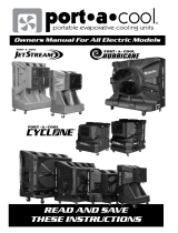
Figure 2-1. Component Locations
A. Exhaust Enclosure E Data Label I. Fuel Regulator M. Oil Dipstick
B. Automatic Voltage
Regulator (AVR)
F. Control Pad J. Battery Compartment N. Composite Base
C. Engine Air Filter G. Circuit Breakers K. Oil Filter
D. AVR Air Filter H. Fuel Inlet (Back) L. Oil Tank
001380
C
D
E
G
H
I
J
L
M
N
A
B
K
F

General Information
Owner’s Manual for 60 Hz EcoGen™ Generator 7
Specifications
Generator
Engine
The specification sheet for this generator was included in
the documentation provided with the unit at the time of
purchase. For additional copies, consult your local
Independent Authorized Service Dealer.
Model 15 kW EcoGen
Rated Voltage 240
Rated Maximum Load
Current (Amps) at 240 Volts
(LP and NG)*
62.5
Main Circuit Breaker 65 Amp
Phase 1
Rated AC Frequency 60 Hz
Battery Requirement Group 26R, 12 Volts and 525 CCA Minimum (Generac Part No. 0H3421S)
Unit Weight in Lbs. (kilos) 536 (243)
Enclosure Aluminum
Normal Operating Range This unit is tested in accordance to UL 2200 standards with an operating
temperature of -20º F (-29º C) to 122º F (50º C). For areas where temperatures fall
below 32º F (0º C) a cold weather kit is recommended. When operated above 77º
F (25º C) there may be a decrease in engine power. Please reference the engine
specifications section.
These generators are rated in accordance with UL 2200, Safety Standard for Stationary Engine Generator
Assemblies, and CSA-C22.2 No. 100-04 Standard for Motors and Generators.
Model 15 kW EcoGen
Type of Engine GT-999
Number of Cylinders 2
Displacement 999 cc
Cylinder Block Aluminum w/Cast Iron Sleeve
Recommended Spark
Plug
RC12YC
Spark Plug Gap 0.040 in. (1.02 mm)
Starter 12 VDC
Oil Capacity Including
Filter
Approx. 3.75 Quarts / 3.55 Liters
Recommended Oil Filter Part #070185E
Recommended Air Filter Part #0J8478
Maximum wattage and current is subject to and limited by such factors as fuel BTU/joules content, ambient
temperature and altitude. Maximum power decreases about 3.5 percent for each 1,000 feet (304.8 meters) above
sea level, and also will decrease about 1 percent for each 10° F (6º C) above 60º F (15º C) ambient temperature.

General Information
8 Owner’s Manual for 60 Hz EcoGen™ Generator
Protection Systems
The generator may have to run for long periods of time
with no operator present to monitor the engine/generator
conditions. Therefore, the generator is equipped with a
number of systems to automatically shut down the unit to
protect it against potentially damaging conditions. Some
of these systems are as follows:
Alarms:
Warnings:
The control panel contains a display which alerts the
operator when a fault condition occurs. The above list is
not all-inclusive. For more information about alarms and
control panel operation, see Section 3 Operation.
NOTE: A warning indicates a condition on the generator
that should be addressed but will not shut the generator
down. An alarm will shut the generator down to protect
the system from any damage. In the event of an alarm,
an owner can clear the alarm and restart the generator
prior to contacting an Independent Authorized Service
Dealer. If the intermittent issue occurs again, contact an
Independent Authorized Service Dealer.
Emissions
The United States Environmental Protection Agency (US
EPA) (and California Air Resources Board (CARB), for
engines/equipment certified to California standards)
requires that this engine/equipment complies with
exhaust and evaporative emissions standards. Locate
the emissions compliance decal on the engine to
determine applicable standards. For emissions warranty
information, please reference the included emissions
warranty. It is important to follow the maintenance
specifications in the manual to ensure that the engine
complies with the applicable emissions standards for the
duration of the product’s life.
This generator is certified to operate on Liquid Propane
Vapor fuel or pipeline Natural Gas.
The Emission Control System code is EM (Engine
Modification). The Emission Control System on this
generator consists of the following:
Fuel Requirements
The engine has been fitted with a dual fuel carburetion
system. The unit will run on natural gas or LP gas
(vapor), but it has been factory set to run on natural gas.
The fuel system will be configured for the available fuel
source during installation.
Recommended fuels should have a BTU content of at
least 1000 BTUs per cubic foot (37.26 megajoules per
cubic meter) for natural gas, or at least 2500 BTUs per
cubic foot (93.15 megajoules per cubic meter) for LP gas
(vapor).
NOTE: If converting to LP gas from natural gas, a
minimum LP tank size of 250 gallons (946 liters) is
recommended. See the Installation Manual for complete
procedures and details.
Battery Requirements
Group 26R, 12V, minimum 525 CCA (Generac part no.
0H34215).
For proper battery maintenance procedures, see
Maintenance.
Battery Charger
The battery charger is integrated into the control panel
module. It operates as a Smart Charger which verifies
output charging levels are safe and continuously
optimized to promote maximum battery life.
Engine Oil Requirements
For proper oil viscosity, see chart in Figure 4-2.
•High Temperature
•Low Oil Pressure
•Overcrank
•Overspeed
•Overvoltage
•Undervoltage
•Overload
•Underspeed
•RPM Sensor Loss
•Wiring Error
•Fuse Problem
•Stepper Overcurrent
• Charger Warning
• Charger Missing AC
• Low Battery
•USB Warning
•Download Failure
System Components
Air Induction
- Intake Pipe and Manifold
- Air Cleaner
Fuel Metering
- Carburetor and Mixer Assembly
- Fuel Regulator
Ignition
- Spark Plug
- Ignition Module
Exhaust
- Exhaust Manifold
- Muffler
(000105)
DANGER
Explosion and Fire. Fuel and vapors are
extremely flammable and explosive. Add fuel
in a well ventilated area. Keep fire and spark
away. Failure to do so will result in death
or serious injury.

General Information
Owner’s Manual for 60 Hz EcoGen™ Generator 9
Replacement Parts
Accessories
Performance enhancing accessories are available for air-cooled generators.
NOTE: Contact an Independent Authorized Service Dealer or visit www.generac.com for additional information on
replacement parts, accessories, and extended warranties.
Description 15 kW EcoGen
26R Exide Battery 0H34215
Spark Plug 0G0767A
Oil Filter 070185E
Air Filter 0J8478
Control Panel Fuse 0D7178T
Accessory Description
Cold Weather Kit
006212-0
Recommended in areas where temperatures fall below 32 ºF (0 ºC).
Scheduled Maintenance Kit
006829-0
Includes all pieces necessary to perform maintenance on the generator along
with oil recommendations.
Mobile Link™ (USA only)
006463-0
Provides a personalized web portal that displays the generator status,
maintenance schedule, event history and much more. This portal is accessible
via computer, tablet or smart phone. Sends emails and/or text notifications the
moment there is any change in the generator’s status. Notification settings can
be customized to what type of alert is sent and how often. For more
information, visit www.MobileLinkGen.com.
Touch-Up Paint Kit
005704-0
Very important to maintain the look and integrity of the generator enclosure.
This kit includes touch-up paint and instructions.
Wireless Local Monitor
006664-0
Completely wireless and battery powered, the Wireless Local Monitor provides
you with instant status without ever leaving the house. Status lights (red,
yellow and green) alert owners when the generator needs attention. Magnetic
backing permits refrigerator mounting and gives a 600 foot line of sight
communication.

General Information
10 Owner’s Manual for 60 Hz EcoGen™ Generator
This page intentionally left blank.

Operation
Owner’s Manual for 60 Hz EcoGen™ Generator 11
Section 3: Operation
Site Prep Verification
It is important that the generator is installed in such a way
that the airflow into and out of the generator is not
impeded. Verify that all shrubs or tall grasses have been
removed within 3 ft. (0.91m) of the intake and discharge
louvers on the sides of the enclosure. It is also important
that the generator is not subject to water intrusion. Verify
that all potential sources such as water sprinklers, roof
run-off, rain gutter downspouts and sump pump
discharges are directed away from the generator
enclosure.
Turn the generator OFF before performing maintenance.
Remove 7.5 Amp fuse, T1 and T2 battery charge fuses,
and disconnect battery cables to prevent accidental start
up. Disconnect the NEGATIVE (-) cable first, then
disconnect the POSITIVE (+) cable. When connecting
the cables, connect the POSITIVE cable first, the
NEGATIVE cable last.
Side Compartment
Local codes may require this compartment to be locked.
A hasp is provided so the owner/operator can secure the
compartment with a padlock. Check local codes for side
compartment locking requirements.
Figure 3-1. Open Side Compartment
Main Circuit Breaker (Generator Disconnect)
See “A” in Figure 3-1. This is a 2-pole breaker rated
according to relevant specifications.
LED Indicator Lights
See “B” in Figure 3-1.
• Green LED “Ready” light is on when battery pack
power is present and the control panel button is in
the AUTO position. This also indicates when the
generator is running.
• Red LED “Alarm” light is on when the generator is
OFF or a fault is detected. Contact an authorized
servicing dealer.
• Yellow LED “Maintenance” light.
NOTE: Yellow LED may be on at the same time as either
the Red or Green LED.
120V GFCI Outlet/15 Amp Breaker
See “C” in Figure 3-1. Some units are equipped with an
external 15 Amp, 120 volt GFCI convenience outlet
located in the top corner of the compartment.
When the generator is running, in the absence of the
normal power source, this outlet may also be used to
power items outside the home such as lights or power
tools. This outlet may also be used when the normal
power source is present by running the generator in
manual mode.
This outlet does not provide power if the generator is not
running. Do not use this outlet when the generator is in
Exercise mode. This outlet is protected by a 15 Amp
circuit breaker in the side compartment.
Generator Enclosure
The lid will be locked. A set of keys is attached to the
circuit breaker box door with a cable tie.
1. Cut the cable tie to remove the keys.
2. Use the keys to open the lid of the generator.
NOTE: The enclosed keys provided with this unit are
intended for service personnel use only.
Automatic start-up. Disconnect normal power source
and render unit inoperable before working on unit.
Failure to do so will result in death or serious injury.
(000236)
DANGER
(000182)
WARNING
001383
B
C
A

Operation
12 Owner’s Manual for 60 Hz EcoGen™ Generator
Figure 3-2. Circuit Breaker Box and Keys
(As Shipped)
3. There are two locks securing the lid, one on each
side (A in Figure 3-3). To properly open the lid,
press down, on the lid, above the side lock and
unlock the latch.
4. Repeat for the other side. If pressure is not applied
from the top, the lid may appear stuck.
NOTE: Always verify that the side locks are unlocked
before attempting to lift the lid.
5. Once the lid is open, remove the front access
panel by lifting it up and out.
NOTE: Always the lift the front access panel up before
pulling away from enclosure (B and C in Figure 3-3). Do
not pull the panel away from the enclosure before lifting
up (D in Figure 3-3).
Figure 3-3. Side Lock Location and Front Panel Removal
000932
000597
A
A
001028
B DC

Operation
Owner’s Manual for 60 Hz EcoGen™ Generator 13
Control Panel Interface
The Control Panel Interface is located under the lid of the
enclosure. Before attempting to lift the lid of the
enclosure, verify that both left and right side locks are
unlocked. To remove the front cover, lift the cover straight
up to disengage the side hooks, then tilt and lift it away
from the unit.
When closing the unit, verify that both left and right side
locks are securely locked.
NOTE: All appropriate panels must be in place during
any operation of the generator. This includes operation
by a servicing technician while conducting
troubleshooting procedures.
Figure 3-4. Generator Control Panel
With the control pad set to AUTO, the engine may crank
and start at any time without warning. To prevent possible
injury that might occur during sudden starts, always set
the control pad to OFF and remove the 7.5 amp fuse
before working on or around the generator or the
electrical loads that are to be powered by the generator.
For added security, place a DO NOT OPERATE tag or
placard at the control pad and the electrical loads that are
to be powered by the generator.
Never run the generator with any access panel removed.
Activation
To receive an activation code, you must have the unit serial
number and go to: www.generac.com, “Service & Support”
Tab and then “Activate Your Home Standby” under the
“Generac Owners” list. You can also receive an activation
code by calling 1–888–9ACTIVATE (1–888–922–8482).
Activating the generator is a simple, one–time process
that is guided by the controller screen prompts. Once the
product is activated, the controller screen will not prompt
you to activate again, even if you disconnect the
generator battery, fuse and battery charge circuit (T1 60
Hz / T1 & T2 50 Hz).
After obtaining your activation code, please complete the
following steps at the generator’s control panel:
1. Upon first power up of the generator, the display
interface will begin an installation wizard.
NOTE: If the unit has already been powered up, it will be
necessary to disconnect the generator battery, fuse and
battery charge circuit (T1 60 Hz / T1 & T2 50Hz).
2. The installation wizard will prompt the user to set
the fuel type and after choosing fuel type and
“Enter”, the display will then annunciate “Activate
me (ENT) or ESC” to run in MANUAL.
3. Press Enter and use the up/down arrows and the
enter keys to put the activation code in.
NOTE: If you push ESC to run in MANUAL, the unit will
not function in AUTO. To enter the activation code at a
later time, it will be necessary to disconnect the generator
battery, fuse and battery charge circuit (T1).
If the unit is not activated, the install wizard will only allow
the programming to operate the generator. These
settings are: Current Date/Time and Exercise Day/Time
and annunciate “NOT ACTIVATED”.
It the unit is activated, the install wizard will allow further
programming parameters and Auto operation. The
maintenance intervals will be initialized when the
exercise time is entered. The exercise settings can be
changed at any time via the EDIT menu. If the 12 volt
battery is disconnected or the fuse removed, the
installation wizard will operate upon power restoration.
The only difference is the display will only prompt the
customer for the current Time and Date.
001428

Operation
14 Owner’s Manual for 60 Hz EcoGen™ Generator
Cold Smart Start
The Cold Smart Start feature can be enabled in the EDIT
menu. When enabled, the generator will monitor ambient
temperature and adjust its warm-up delay based on
temperature. If the ambient temperature conditions are
below 50 ºF (10 °C) upon startup in AUTO mode, the
generator will warm up for 30 seconds allowing the
engine to warm before the load is applied. If the
temperature is at or above 50 ºF (10 °C), the generator
will startup with the normal warm-up delay of six
seconds.
Using the Auto/Off/Manual Interface Menu
Damage caused by mis-wiring of the interconnect wires is not warrantable.
Button Description of Operation
AUTO
Press to activate fully automatic operation. Green LED illuminates to confirm that system is in AUTO mode.
Transfer to standby power occurs if 2-wire start signal is enabled.
MANUAL Press to crank and start engine. Blue LED illuminates to confirm that system is in MANUAL mode.
OFF Press to shut down engine, if running. Red LED illuminates to confirm that system is in OFF mode.

Operation
Owner’s Manual for 60 Hz EcoGen™ Generator 15
Menu Navigation
Menu System Navigation
To get to the MENU, use the “Escape” button from any page. It may require pressing it several times before getting to
the MENU page. Navigate to the desired menu by using the
↑/↓ buttons. When the desired menu is displayed and
flashing, press the “Enter” button. See Figure 3-5 Navigation Menu.
Change Time and Date
To change the time and date after activation, see Figure
3-5 Navigation Menu. If power is lost (battery is discon-
nected/reconnected, 7.5 amp control pad fuse is
removed/installed, etc.), the display automatically
prompts the user for the Time and Date. All other infor-
mation is retained in memory.
Programmable Timers
Dealer Programmable
NOTE: A dealer pass code is required.
High Run Speed Timer
A programmable high run speed timer is provided. The
timer controls the length of time the generator runs at
maximum speed after application of a large load (such as
an air conditioner). The time can be increased to prevent
the potential cycling of engine RPM as loads turn on and
off. For example, if the timer is currently set to ten
minutes, and the normal AC cycling time is 15 minutes,
increasing the timer to 20 minutes would prevent the
engine speed from ramping up and down every ten
minutes between AC cycles (even though fuel
consumption would increase).
Cooldown
Cooldown can be set to YES or NO for compatibility with
installation configurations. The default setting is NO.
USB Port for Firmware Updates
A USB port is located beneath the rubber flap adjacent to
the control pad, and is provided for firmware updates.
Firmware updates must be performed by an Independent
Authorized Service Dealer.
NOTE: The USB port is intended for use with a USB
thumb drive only. The USB port is not intended for
charging devices such as phones or laptops. Do not
connect any consumer electronics to the USB port.
Feature Description
System Menus
HOME Screen
The system returns to the Home screen if the control pad is not used for five minutes. The screen normally
displays a Status message, such as Ready to Run (Auto mode) or Switched to OFF (Off mode), and the
total Hours of Protection. If an active alarm/warning condition occurs, the associated Alarm/Warning
message is displayed. To clear the Alarm/Warning message, press OFF on the control pad followed by
ENTER. In the event of multiple Alarms/Warnings, the next message is then displayed. The highest priority
alarm is always displayed first.
MAIN MENU
Enables the operator to navigate the software using UP ARROW, DOWN ARROW, ENTER and ESCAPE.
The Main Menu can be accessed from any sub menu by consecutively pressing ESCAPE. Each time
ESCAPE is pressed, the preceding menu is displayed. The Main Menu is reached when the System,
Date/Time, Battery, and Sub Menus are displayed.
Navigation
ESCAPE Used to abort a routine or back up to the preceding menu.
ENTER Used to make a selection or save an entry.
UP ARROW
DOWN ARROW
Used to move forward or backward from menu to menu or to scroll forward or backward (increment or
decrement) through available selections.
NOTE: Pressing the control pad illuminates the backlight for 30 seconds. The backlight also illuminates for 30 seconds
whenever an active Alarm/Warning message is displayed.

Operation
16 Owner’s Manual for 60 Hz EcoGen™ Generator
Figure 3-5. Navigation Menu
ECOGEN HSB MENU MAP
“Run Log”
ESC
ENTER
ENTER
SYSTEM
BATTERY
DATE/TIME
SUB MENUS
HISTORY
EDIT
Firmware Update
Å Press Enter Æ
ESC
ESC
ENTER
Current Date/Time
Å 2/12/13 12:22 Æ
ESC
ENTER
ENTER
ESC
ESC
ESC
ENTER
ESC
ESC
ENTER
ENTER
ESC
ENTER
ENTERENTER
ENTER
ENTER
ENTER
ESC
Switched to “OFF”
Hours of Protection
0 (H)
Language
Å English Æ
Fuel Selection
Å NG or LP Æ
Possible Message(s)
Corrupted File
Invalid File
File Not Found
Unsupported Device
Firmware Update
Å Insert USB Æ
“Alarm Log”
- Alarm Log +
- Run Log +
- 1 thru 50 +
- 1 thru 50 +
Warning Message(s)
"Low Battery"
"FIRMWARE ERROR-9"
"Fuel Pressure"
"Battery Problem"
"Charger Warning"
"Charger Missing AC"
"Overload Warning"
"Overload Cooldown"
"SEEPROM ABUSE"
"USB Warning"
"Download Failure"
Running Manual
Running-Utility Lost
Running-Remote Start
Running-2 Wire Start
Switched Off
Stopped - Auto
Stopped - Alarm
Alarm Message(s)
"High Engine Temp."
"Low Oil Pressure"
"Overcrank"
"Overspeed"
"RPM Sense Loss"
"Underspeed"
"Internal Fault"
"FIRMWARE ERROR-7"
"WIRING ERROR"
"Over Voltage"
"Under Voltage"
"Overload Remove Load"
"Low Volts Remove Load"
"Stepper Over Current"
"Fuse Problem"
ESC
Select Min (0-59)
- 0 +
ESC
ESC
Select Hour (0-23)
- 14 +
Language
+ English -
Fuel Selection
+ NG or LP -
Language
+ Espanol -
Language
+ Francais -
+
-
+
-
Battery Condition
“Good” “Inspect Battery” or “Check Battery”
001382a
ESC
ENTER
Cold Smart Start?
Å
YES or NO
Æ
ESC
Cold Smart Start?
- YES or NO +
/