Curtis CAFE1DB10A000 User guide
- Category
- Coffee making accessories
- Type
- User guide
This manual is also suitable for

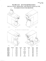
CAFE Series Glass Decanter
Pourover Coffee Brewing System
USER GUIDE
READ AND SAVE THESE INSTRUCTIONS
NOTICE TO INSTALLER: Please leave this booklet with the machine.
Style Varies
'$$"'&(-"44%&$"/5&3'30/5$07&3øøøøø "
'SFW"

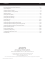
CONTENTS CL35
.H\)HDWXUHV6SHFLÀFDWLRQV6\VWHP5HTXLUHPHQWV..............................................................................................FS35
,PSRUWDQW6DIHJXDUGV ...............................................................................................................................................IS2
,QVWDOODWLRQ,QVWUXFWLRQV*HQHUDO ...............................................................................................................................II4
,QVWDOODWLRQ,QVWUXFWLRQV/HYHOLQJ(OHFWULFDO..............................................................................................................II5
2SHUDWLQJ,QVWUXFWLRQV ............................................................................................................................................OI28
&OHDQLQJ,QVWUXFWLRQV%UHZHU .................................................................................................................................CI1
&OHDQLQJ,QVWUXFWLRQV'HFDQWHU ............................................................................................................................ CI11
&OHDQLQJ,QVWUXFWLRQV'HOLPLQJ ...........................................................................................................................CI12
3URJUDPPLQJ*XLGH ............................................................................................................................................. 3*
5RXJK,Q'UDZLQJ................................................................................................................................................. 5'
,OOXVWUDWHG3DUWV5HFRPPHQGHG3DUWV0DLQ&KDVVLV .......................................................................................... IP64
,OOXVWUDWHG3DUWV5HFRPPHQGHG3DUWV7DQN$VVHPEO\'RPHVWLF ....................................................................... IP66
,OOXVWUDWHG3DUWV5HFRPPHQGHG3DUWV7DQN$VVHPEO\([SRUW ......................................................................... IP192
(OHFWULFDO6FKHPDWLF'RPHVWLF ............................................................................................................................ ES68
(OHFWULFDO6FKHPDWLF([SRUW ................................................................................................................................ES69
7URXEOHVKRRWLQJ*XLGH*HQHUDO ..........................................................................................................................7*
7URXEOHVKRRWLQJ*XLGH:DUPHU&LUFXLW ...............................................................................................................7*
3URGXFW:DUUDQW\....................................................................................................................................................3:
Contact Information
Wilbur Curtis Co., Inc.
6913 Acco Street | Montebello, CA 90640 US
Phone: 323-837-2300 | Toll Free: 800-421-6150
Email: [email protected] | Web: www.wilburcurtis.com
'PSUIFMBUFTUTQFDJmDBUJPOTBOEJOGPSNBUJPOHPUPXXXXJMCVSDVSUJTDPN
5PMM'SFF].POEBZ'SJEBZ
A.M. - 4:00 P.M. PT
Email: [email protected]
%VFUPDPOUJOVFEQSPEVDUJNQSPWFNFOUUIFQSPEVDUTJMMVTUSBUFEQIPUPHSBQIFEJOUIJTHVJEFNBZWBSZTMJHIUMZGSPNUIFBDUVBMQSPEVDU
$"'&(-"44%&$"/5&3$0/5&/54-*45øø "

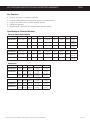
KEY FEATURES/SPECIFICATIONS/SYSTEM REQUIREMENTS FS35
Key Features
• Pourover operation – No plumbing required.
• Powerful heating element provides quick recovery for faster brewing.
• Large-volume water tank for greater brewing capacity.
• Space-saving design.
• Stainless steel construction with textured black powder coating.
6SHFLÀFDWLRQV6HOHFWHG0RGHOV
(OHFWULFDO6XSSO\5HTXLUHPHQWV
02'(/ '(6&5,37,21 3+$6( 92/76 $036 +($7,1*&21),* :,5( :$776 +(57= &$3$&,7<
&$)('%$
Pourover 1 Station 1 PH 120 V 12.9 A 1 x 1450 W 2W + G 1550 W 50/60 Hz
4.2 gal/hr
[15.9 l/hr]
&$)('%$ Pourover 2 Station 1 PH 120 V 13.8 A 1 x 1450 W 2W + G 1650 W 50/60 Hz
4.2 gal/hr
[15.9 l/hr]
&$)('%$ Pourover 3 Station 1 PH 120 V 14.6 A 1 x 1450 W 2W + G 1750 W 50/60 Hz
4.2 gal/hr
[15.9 l/hr]
(;3257
&$)('%$ Pourover 1 Station 1 PH 230 V 10.0 A 1 x 2000 W 2W + G 2295 W 50/60 Hz
6.0 gal/hr
[22.7 l/hr]
&$)('%$ Pourover 2 Station 1 PH 230 V 10.4 A 1 x 2000 W 2W + G 2400 W 50/60 Hz
6.0 gal/hr
[22.7 l/hr]
&$)('%$ Pourover 3 Station 1 PH 230 V 10.9 A 1 x 2000 W 2W + G 2150 W 50/60 Hz
6.0 gal/hr
[22.7 l/hr]
'LPHQVLRQV
02'(/
+(,*+7
:,'7+ '(37+ 6+,3:(,*+7 6+,3&8%(
&$)('%$
17.61”
[44.7 cm]
9.25”
[23.5 cm]
17.93”
[45.5 cm]
24.0 lbs
[10.9 kg]
3.92 cu. ft.
[0.11 m
3
]
&$)('%$
19.05”
[48.4 cm]
9.25”
[23.5 cm]
17.93”
[45.5 cm]
25.0 lbs
[11.3 kg]
3.92 cu. ft.
[0.11 m
3
]
&$)('%$
17.61”
[44.7 cm]
15.81”
[40.2 cm]
17.93”
[45.5 cm]
32.00 lbs
[14.5 kg]
6.14 cu ft
[0.17 m
3
]
(;3257
&$)('%$
17.61”
[44.7 cm]
9.25”
[23.5 cm]
18.50”
[47.0 cm]
24.0 lbs
[10.9 kg]
3.92 cu. ft.
[0.11 m
3
]
&$)('%$
19.05”
[48.4 cm]
9.25”
[23.5 cm]
18.50”
[47.0 cm]
25.0 lbs
[11.3 kg]
3.92 cu. ft.
[0.11 m
3
]
&$)('%$
17.61”
[44.7 cm]
15.81”
[40.2 cm]
18.50”
[47.0 cm]
32.00 lbs
[14.5 kg]
6.14 cu ft
[0.17 m
3
]
CAFE GLASS DECANTER BREWER, KEY FEATURES/SPECS/SYSTEM REQUIREMENTS 052119A

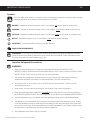
IMPORTANT SAFEGUARDS IS2
Symbols
This is the safety alert symbol. It is used to alert you to potential physical injury hazards. Obey all safety
messages that follow this symbol to avoid possible injury or death.
DANGER - Indicates a hazardous situation which, if not avoided, will result in death or serious injury.
WARNING - Indicates a hazardous situation which, if not avoided, could result in death or serious injury.
CAUTION - Indicates a hazardous situation which, if not avoided, could result in minor or moderate injury.
NOTICE - Indicates a situation which, if not avoided, could result in property damage.
IMPORTANT - Provides information and tips for proper operation.
SANITATION REQUIREMENTS
Important Safeguards/Conventions
WARNING:
• Make sure that this appliance is installed and grounded according to the INSTALLATION
*/4536$5*0/4CZRVBMJmFEQFSTPOOFMCFGPSFBUUFNQUJOHUPVTFJU'BJMVSFUPGPMMPXUIF*/45"--"5*0/
INSTRUCTIONS could result in personal injury or void the warranty.
• This appliance is designed for commercial use. Any service other than cleaning and preventive
maintenance should be performed by an authorized Wilbur Curtis service technician.
• 5PSFEVDFUIFSJTLPGmSFPSFMFDUSJDTIPDL%0/05PQFOUIFTFSWJDFQBOFMT5IFSFBSFOPVTFS
serviceable parts inside.
• Keep hands, arms and other items away from hot surfaces of the unit during operation.
• Clean the appliance and any dispensers completelyCFGPSFVTJOHUIFNGPSUIFmSTUUJNFBDDPSEJOHUP
the CLEANING INSTRUCTIONS. Clean them regularly as instructed in the CLEANING INSTRUCTIONS.
• Use this appliance only for its intended use, brewing/dispensing hot and/or cold beverages/water.
• This appliance is not intended for use by persons (including children) with reduced physical, sensory
or mental capabilities or lack of experience and knowledge, unless they have been given supervision
or instruction concerning use of the appliance by a person responsible for their safety. Children should
be supervised to ensure that they do not play with the appliance.
• Avoid spillage onto the power (mains) connector.
$0''&&5&"#3&8&34*.1035"/54"'&(6"3%44:.#0-4 )
WARNING - 5IJTQSPEVDUDBOFYQPTFZPVUPDIFNJDBMTJODMVEJOH"DSZMBNJEFBOE#JTQIFOPM"#1"
which are known to the State of California to cause cancer and birth defects or other reproductive harm.
'PSNPSFJOGPSNBUJPOWJTJUXXX18BSOJOHTDBHPW

IMPORTANT SAFEGUARDS IS2
$0''&&5&"#3&8&34*.1035"/54"'&(6"3%44:.#0-4 )
CE Requirements
• This appliance must be installed in locations where it can be overseen by trained personnel.
• 'PSQSPQFSPQFSBUJPOUIJTBQQMJBODFNVTUCFJOTUBMMFEXIFSFUIFUFNQFSBUVSFJTCFUXFFO¡$UP¡$
• This appliance is not suitable for outdoor use.
• 5IJTBQQMJBODFTIBMMOPUCFUJMUFENPSFUIBO¡GPSTBGFPQFSBUJPO
• "OFMFDUSJDJBONVTUQSPWJEFFMFDUSJDBMTFSWJDFBTTQFDJmFEJODPOGPSNBODFXJUIBMMMPDBMBOEOBUJPOBMDPEFT
'PSTBGFVTFBOBMMQPMFEJTDPOOFDUJPONVTUCFJODPSQPSBUFEJOUPUIFmYFEXJSJOHJOBDDPSEBODFXJUIUIF
XJSJOHSVMFTPVUMJOFEJODMBVTFPG*&$GPSNFFUJOHUIFNJOJNVNFMFDUSJDBMTBGFUZPGUIJTTUBOEBSE
• This appliance must not be cleaned by water jet.
• 5IJTBQQMJBODFDBOCFVTFECZQFSTPOTBHFEGSPNZFBSTBOEBCPWFJGUIFZIBWFCFFOHJWFOTVQFSWJTJPOPS
instruction concerning use of the appliance in a safe way and if they understand the hazards involved.
• ,FFQUIFBQQMJBODFBOEJUTDPSEPVUPGSFBDIPGDIJMESFOBHFEMFTTUIBOZFBST
• "QQMJBODFTDBOCFVTFECZQFSTPOTZFBSTBOEBCPWFXJUISFEVDFEQIZTJDBMTFOTPSZPSNFOUBMDBQBCJMJUJFT
or lack of experience and knowledge if they have been given supervision or instruction concerning use of the
appliance in a safe way and understand the hazards involved.
• $IJMESFOVOEFSUIFBHFPGZFBSTTIPVMECFTVQFSWJTFEUPFOTVSFUIFZEPOPUQMBZXJUIUIFBQQMJBODF
• If the power cord is ever damaged, it must be replaced by the manufacturer or authorized service personnel
with a special cord available from the manufacturer or its authorized service personnel in order to avoid a
hazard.
• Machine must not be immersed for cleaning.
• $MFBOJOHBOEVTFSNBJOUFOBODFTIBMMOPUCFNBEFCZDIJMESFOVOMFTTUIFZBSFPMEFSUIBOZFBSTBOE
supervised.
• This appliance is intended to be used in household and similar applications such as:
oTUBGGLJUDIFOBSFBTJOTIPQTPGmDFTBOEPUIFSXPSLJOHFOWJSPONFOUT
oCZDMJFOUTJOIPUFMTNPUFMTBOEPUIFSSFTJEFOUJBMUZQFFOWJSPONFOUT
– bed and breakfast type environments.
• This appliance not intended to be used in applications such as:
– farm houses
• Access to the service areas permitted by Authorized Service personnel only.
• 5IF"8FJHIUFETPVOEQSFTTVSFMFWFMJTCFMPXE#"

INSTALLATION INSTRUCTIONS II4
Installation Instructions
Installation Requirements
• A secure surface capable of supporting the weight of the appliance.
• For appliances without an attached cord set: Appropriately sized, UL listed, grounding type power cable to
NFFUUIFFMFDUSJDBMTQFDJmDBUJPOTGPSUIFVOJU*GZPVIBWFRVFTUJPOTBCPVUUIFDPSSFDUDBCMFTJ[FBOEMFOHUI
DPOTVMUBRVBMJmFEJOTUBMMFS'PSBQQMJBODFTUIBUXJMMCFIBSEXJSFEUPBKVODUJPOCPYUIFQPXFSDBCMFNVTUCF
long enoughTPUIBUUIFCSFXFSDBOCFNPWFEGPSDMFBOJOHVOEFSOFBUI
• "HSPVOEFEFMFDUSJDBMDPOOFDUJPOUPBOFMFDUSJDBMDJSDVJUUIBUNFFUTUIFFMFDUSJDBMTQFDJmDBUJPOTPGUIF
appliance (see SPECIFICATIONS). The circuit must be protected by the appropriate sized circuit breaker.
*GZPVBSFOPUDFSUBJOUIBUUIFFYJTUJOHDJSDVJUNFFUTUIFSFRVJSFNFOUTGPSZPVSCSFXFSDPOTVMUBMJDFOTFE
electrician.
WARNING:*NQSPQFSFMFDUSJDBMDPOOFDUJPONBZSFTVMUJOBOFMFDUSJDTIPDLIB[BSE5IJTBQQMJBODFNVTUCF
properly grounded.
WARNING:*GJOTUBMMBUJPOPGBQPXFSQMVHJTSFRVJSFEJUNVTUCFJOTUBMMFEPOMZCZBRVBMJmFEJOTUBMMFS
IMPORTANT:0CTFSWFBMMHPWFSOJOHDPEFTBOEPSEJOBODFT
(&/&3*$/0/1-6.#&%*/45"--"5*0/*/4536$5*0/4 /$

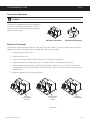
Installation
Leveling
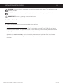
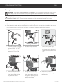
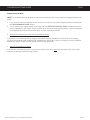
1 Position the brewer on the countertop near an
electrical outlet that meets the SPECIFICATIONS.
Level the brewer left to right and front to back by
turning the bottom of the legs.
Connecting the Brewer Power Plug - Export Units
2 Connect the appropriate type of grounded power plug
to the end of the power cord coming from the back of
the unit.
INSTALLATION INSTRUCTIONS II5
CAFE, INSTALLATION INSTRUCTIONS 121217B
WARNING: Use the leveling legs to level the
brewer only. Do not use them to adjust brewer
height. Do not extend them higher than
necessary.
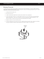
NOTICE - This brewer is shipped with the
thermostat turned ON. DO NOT plug in the
brewer before pouring 3 pots/192 oz. of water
into the opening as instructed below; damage to
the heating element and/or thermostat will result.
&RQ¿JXUDWLRQ
YDULHV
&RQ¿JXUDWLRQ
YDULHV
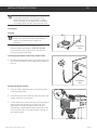
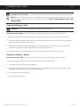
Prepare the Brewer for Use
3 Place an empty glass decanter on the warmer deck,
under the spray head.
4 Insert the empty brew basket into the brew rails of the
brewer, below the control panel.
5 Fill the water tank by slowly pouring room temperature
water through the opening on the top cover, until
water starts running in a steady stream from the
brew basket. It takes approximately three pots or 192
PVODFTUPmMMUIFUBOLJOEJDBUFECZXBUFSDPNJOHPVU
of the brew basket.

INSTALLATION INSTRUCTIONS II5
CAFE, INSTALLATION INSTRUCTIONS 121217B
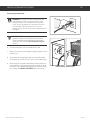
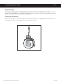
Powering Up the Brewer
6 Connect the power cord to the electrical outlet.
7 Make sure that the circuit breaker supplying power to the
brewer is on.
8 Some brewers are equipped with a main power switch
on the back or front of the unit. Turn it to the ON position.
9 Depending on the water temperature and the electrical
TQFDJmDBUJPOTUIFXBUFSUBOLUZQJDBMMZSFRVJSFTUP
minutes to reach operating temperature. When the water
has heated, the READY TO BREW light will come on.
Power Switch (some units)
WARNING: Connect the power cords only to the
appropriate type and size electrical outlet. If the
electrical outlet is not compatible with the power
cords, have it upgraded by a licensed electrician.
Do not modify the power plug. Do not use an
extension cord. Do not use a power cord/plug that is
damaged.
IMPORTANT: When operating the brewer at
FMFWBUJPOTIJHIFSUIBOGFFUNFUFST
IBWFBRVBMJmFEJOTUBMMFSBEKVTUUIFUIFSNPTUBU
inside the unit. See the PROGRAMMING GUIDE
section.

OPERATING INSTRUCTIONS OI28
$"'&(-"44%&$"/5&3#3&8&301&3"5*/(*/4536$5*0/4øø /$
Brewing Instructions
2 Center an empty decanter
under the brew basket.
3 *OTFSUBDMFBOQBQFSmMUFS
into the brew basket. Fill with
the proper amount of ground
coffee. Level the coffee in the
mMUFS
4 4MJEFUIFmMMFECSFXCBTLFU
into the brew rails under the
control panel. Slide it all the
way back until it stops.
5 Using a second decanter,
pour one full decanter of
room temperature water into
the pourover opening on the
top. The brew time will be
about three minutes.
The brewer should be plugged
in and the “READY TO BREW"
light should be lit. On units
with a rear toggle switch,
make sure it is in the ON
position.
6 Switch on the warmer to
keep the coffee at serving
temperature.
WARNING - TO AVOID SCALDING, AVOID SPLASHING. The brew basket contains hot coffee grounds.
Keep body parts clear of the brewer during brewing. Allow the brew basket to drain before removing it.
NOTICE - #FGPSFQMVHHJOHUIFCSFXFSJOGPSUIFmSTUUJNFmMMUIFXBUFSUBOLBDDPSEJOHUPUIFINSTALLATION
INSTRUCTIONS section. Connecting the power without a full water tank will damage the brewer.
Before Brewing:
• Two decanters are required for brewing coffee, one for pouring water, the other to brew coffee into.
• Some water in the water tank may evaporate if the brewer is left on for long periods of time. When this occurs,
QPVSJOFOPVHIXBUFSUPSFmMMUIFUBOLVOUJMXBUFSDPNFTPVUPGUIFTQSBZIFBECFGPSFCSFXJOH

NOTICE - Do not use cleaning liquids, compounds or powders containing chlorine (bleach) or corrosives.
5IFTFQSPEVDUTQSPNPUFDPSSPTJPOBOEXJMMEBNBHFUIFmOJTIFT USE OF THESE PRODUCTS WILL VOID
THE WARRANTY.
CLEANING INSTRUCTIONS CI1
Cleaning The Brewer - Daily
BREWERS - GENERIC, CLEANING INSTRUCTIONS 080416B
WARNING: HOT SURFACES - To avoid injury, allow the brewer and dispenser(s) to cool before cleaning.
The brewer should be OFF.5VSOUIFCSFXFSPGGCZnJQQJOHUIFSFBSUPHHMFTXJUDIUPUIF0''QPTJUJPO
1 Remove the dispenser(s). Wipe exterior brewer surfaces with a damp cloth to remove spills and debris.
2 Remove the brew basket(s) and clean them in a mild detergent solution. Use a soft bristled brush for hard to
clean areas. Rinse with clean water, then dry.
3 Wipe the spray head area with a cloth soaked in a mild detergent solution. Rinse with a cloth soaked with
clean water removing any residual detergent. Use a clean, soft cloth to dry.
4 Dump out the drip tray(s) (if applicable). Rinse with clean water, then dry with a soft, clean cloth.
Cleaning The Brewer - Weekly
The brewer should be OFF.5VSOUIFCSFXFSPGGCZnJQQJOHUIFSFBSUPHHMFTXJUDIUPUIF0''QPTJUJPO
1 Remove the spray head(s), unscrewing counterclockwise from the dome plate.
2 Thoroughly clean and rinse the dome plate area.
3 Clean the brew basket rails with a brush soaked with a mild detergent solution. Rinse the area with a cloth
soaked with clean water, removing any residual detergent.
4 Dry the area with a soft, clean cloth.
5 Reattach the spray head(s).
WARNING: DO NOT immerse the brewer in water or any other liquid.

CLEANING INSTRUCTIONS CI11
(-"44%&$"/5&3$-&"/*/(*/4536$5*0/4ø /$
Glass Decanters
Avoid injury or damage when cleaning glass decanters: Do not clean with materials that scratch. Curtis glass
decanters are dishwasher safe, or may be hand washed. To clean, prepare a mild solution of detergent and warm
water or urn cleaning solution intended for coffee decanters.
Cleaning the Glass Decanter
Remove the decanter from the brewer and rinse. Immerse the decanter in the detergent solution and clean it with
a sponge brush. Rinse it out thoroughly with clean warm water and dry.

CLEANING INSTRUCTIONS CI12
#3&8&3%&-*.*/($-&"/*/(*/4536$5*0/4ø /$
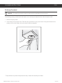
De-liming Procedure*
NOTICE - 5IFEFMJNJOHQSPDFEVSFNVTUCFQFSGPSNFECZBRVBMJmFETFSWJDFUFDIOJDJBO
5IFEFMJNJOHTQSJOHQSPWJEFEXJUIUIFCSFXFSJTGPSDMFBOJOHMJNFEFQPTJUTGSPNXJUIJOUIFTJQIPOUVCF
3FNPWFUIFTQSBZIFBE
2 *OTFSUTQSJOHJOUPUIFTJQIPOUVCF5XJTUUIFTQSJOHDMPDLXJTFBTZPVQVTIJOXBSE0ODFQBTUUIFCFOEJOUIF
UVCJOHZPVDBOTMJEFJUCBDLBOGPSUIUPSFNPWFIBSEMJNFEFQPTJUT
5IJTQSPDFEVSFNBZOFFEUPCFQFSGPSNFEEBJMZJOBSFBTXJUIFYUSFNFMZIBSEXBUFS

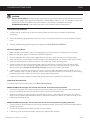
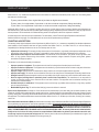
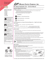
Electronic Thermostat
The electronic thermostat has two settings; 200°F (93°C) and 190°F (88°C). The factory default setting is 200°F. If
operating the brewer at altitudes higher than 4000 feet (1200 m), set it to 190°F.
1 Unplug the brewer power cord.
2 Remove the back cover.
3 Locate the thermostat, attached to a bracket near the top of the compartment.
4 Locate the temperature setting jumper pins. It is labeled “200°F” on the printed circuit board.
5 When jumpered, the board is set to 200ºF. When the jumper is removed, it is set to 190ºF. When setting
the thermostat to 190ºF, slip the jumper over (only) one of the pins, in the event that the board needs to be
changed back.
6 Replace the back cover and reconnect power.
continued....
Thermostat Adjustment
The brewer is equipped with either an electronic or
mechanical (capillary) type thermostat. The tank
temperature (thermostat) adjustment procedure is
different for each type.
PROGRAMMING GUIDE PG11
$"'&130(3"..*/((6*%&ø "
WARNING -5IFGPMMPXJOHQSPDFEVSFTBSFUPCFQFSGPSNFEPOMZCZBRVBMJmFEJOTUBMMFSPSTFSWJDFUFDIOJDJBO
Electronic Thermostat Mechanical Thermostat
Jumper in
200°F position
(default)
Jumper in
190°F position
Remove jumper
to change
setting

PROGRAMMING GUIDE PG11
$"'&130(3"..*/((6*%&ø "
Mechanical Thermostat
The mechanical thermostat has an adjustment screw used to set the temperature. The factory default setting is
200°F (93°C). When operating the brewer at higher elevations, reduce the operating temperature by 2°F for each
1000 feet of elevation above 4000 feet (1200 m).
1 Unplug the brewer power cord.
2 Remove the top cover.
3 Locate the thermostat, attached to a bracket near the back of the compartment.
4 6TJOHBnBUCMBEFTDSFXESJWFSUVSOUIFBEKVTUNFOUTDSFXPOUPQPGUIFUIFSNPTUBUDPVOUFSDMPDLXJTFUP
MPXFSUIFUFNQFSBUVSFPGBUVSOPOUIFTDSFXMPXFSTUIFUFNQFSBUVSFBQQSPYJNBUFMZ¡'¡$
When the screw is turned all the way clockwise, the thermostat is set to 200°F.
5 Replace the back cover and reconnect power.
6 If the brew temperature of the water is too cool, readjust following the above steps, keeping in mind that
too high a temperature setting at higher altitudes may cause the water in the tank to boil.
Adjustment
screw

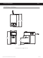
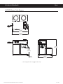
ROUGH-IN DRAWINGS RD41
CAFE1DB Series Coffee Brewers
CAFE GLASS DECANTER BREWER, ROUGH-IN DRAWING 052119A
17.61 in
[44.7 cm]
7.08 in
[18.0 cm]
17.93 in
[45.5 cm]
18.50 in*
[47.0 cm]
9.25 in
[23.5 cm]
1.52 in
[3.9 cm]
* Units equipped with a toggle switch only

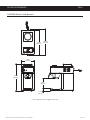
ROUGH-IN DRAWINGS RD41
CAFE2DB Series Coffee Brewers
CAFE GLASS DECANTER BREWER, ROUGH-IN DRAWING 052119A
19.05 in
[48.5 cm]
7.08 in
[18.0 cm]
17.93 in
[45.5 cm]
18.50 in*
[47.0 cm]
9.25 in
[23.5 cm]
1.52 in
[3.9 cm]
* Units equipped with a toggle switch only

ROUGH-IN DRAWINGS RD41
CAFE3DB Series Coffee Brewers
CAFE GLASS DECANTER BREWER, ROUGH-IN DRAWING 052119A
17.61 in
[44.7 cm]
* Units equipped with a toggle switch only
1.52 in
[3.9 cm]
17.93 in
[45.5 cm]
18.50 in*
[47.0 cm]
7.08 in
[18.0 cm]
15.81 in
[40.2 cm]

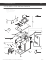
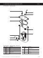
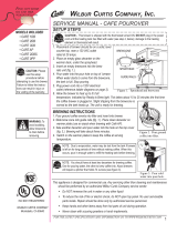
ILLUSTRATED PARTS LIST IP64
CAFE GLASS DECANTER BREWER, ILLUSTRATED PARTS/RECOMMENDED PARTS 052219A
13
10
11
6
21
9
17
7C
14
23
4
3
5
19A
19B
8A
8B
8C
20A
20B
20C
16A
16B
16C
16D
16E
16F
2A
2B
12A
12B
15A
15B
7A
7B
22
18
1
CAFE1DB, CAFE2DB, CAFE3DB - Main Chassis - Exploded View
Water tank assemblies:
- Domestic, see section IP66
- Export, see section IP192
&KDVVLVFRQ¿JXUDWLRQYDULHVZLWKPRGHO

ILLUSTRATED PARTS LIST IP64
CAFE GLASS DECANTER BREWER, ILLUSTRATED PARTS/RECOMMENDED PARTS 052219A
ITEM # PART # DESCRIPTION
1 WC-54121 PAN, POUR CAFÉ
2A WC-207
1,3,5
LIGHT, BREW 115V GREEN
2B WC-208
2,4,6
LIGHT, BREW 250V GREEN
3 WC-3502 LEG, 8-32 STUD SCREW BUMPER
4 WC-3645
SPRING, DELIMING .041 X 20”
GALVANIZED WIRE HARD DRAWN
5 WC-54118 TRAY, ASSY CAFE POUR OVER
6 WC-4213-P NUT, 5/8 LOCK PLATED
7A WC-735-101K
1,3,5*
KIT, CONTROL MODULE RETROFIT
7B WC-735-101
1,3,5*
THERMOSTAT, TEMPERATURE
CONTROL 120VAC POUROVER CAFE
7C WC-504
2,4,6
THERMOSTAT, CAPILLARY SPST 250V
25A GEM
8A WC-39372
1,4
LABEL, SW PANEL CAFÉ 1 CURTIS
8B WC-39373
2,5
LABEL, SW PANEL CAFÉ 2 CURTIS
8C WC-39374
3,6
LABEL, SW PANEL CAFÉ 3 CURTIS
9 WC-29025 SPRAYHEAD, PURPLE ADVANCE FLOW
10 WC-29054 TUBE, W/A CAFE POUR OVERS
11 WC-3621-101
BREW CONE, NON-METAL UNIVERSAL
(WITH SPLASH POCKET)
12A WC-37135
1,3,5
KIT, WARMER ELEMENT 100W 120V W/
PLATE ALPHA/AW
12B WC-975
2,4,6
WARMER, ASSY COMPLETE 100W 220V
13 WC-5310 TUBE, 5/16 ID x 1/8W SILICONE GEN USE
14 WC-1408 CORD GRIP, 7/8” O.D.
15A WC-1200
1,3,5
CORD, 14/3 SJTO 6’ BLK W/PLUG
15B WC-1231-103
2,4,6
CORD, 2.5 mm² PRE-CUT W/
CONNECTORS
ITEM # PART # DESCRIPTION
16A WC-13302-101
1
HARNESS ASSY, CAFE 1BD FOR
ELECTRONIC THERMOSTAT
16B WC-13302
2
HARNESS ASSY, CAFE 1 220V
16C WC-13303-101
3
HARNESS ASSY, CAFE 2DB FOR
ELECTRONIC THERMOSTAT
16D WC-13303
4
HARNESS ASSY, CAFE 2 220V
16E WC-13304-101
5
HARNESS ASSY, CAFE 3DB FOR
ELECTRONIC THERMOSTAT
16F WC-13304
6
HARNESS ASSY, CAFE 3 220V
17 WC-5231 COMPOUND, HEAT SINK 5OZ
18 WC-103
2,4,6
SWITCH, TOGGLE NON-LIT DPST 25A
125/250VAC RESISTIVE
19A WC-68101
3
TOP, WARMER ASSY 120V CAFÉ 2
19B WC-68103
4
TOP, WARMER ASSY 220V CAFÉ 2
20A WC-165
1,3,5
SWITCH, WARMER (RED) 120V NEON
SPST 20A/250V HI TEMP CAFE/AW
20B WC-166
2,4,6
SWITCH, WARMER (RED) 250V NEON
SPST 20A/250V HI TEMP CAFE/AW
20C WC-137
2,4,6
SWITCH, WARMER (RED) 220V (OLDER
UNITS)
21 WC-4426 SCREW, 8-32x3/8 PH HEAD TRUSS
22 WC-4442 SCREW, 8-32x3/8 PH HD TRUSS BLACK
23 WC-4514 SCREW, 8-32x3/8 PAN HEAD PH SS
CAFE1DB, CAFE2DB, CAFE3DB - Main Chassis - Parts List
1
CAFE1DB10A000,
2
CAFE1DB30A000,
3
CAFE2DB10A000,
4
CAFE2DB30A000,
5
CAFE3DB10A000,
6
CAFE3DB30A000
* IMPORTANT: The mounting location of the temperature control module was changed on newer units to increase reliability. If replacing a control module that is mounted near the
top of the water tank, order item 7A (includes parts and instructions for installing the replacement module in the new location). If the module is mounted just above the base of the
chassis, order item 7B.
ITEM # PART # DESCRIPTION
9 WC-29025 SPRAYHEAD, PURPLE ADVANCE FLOW
13 WC-5310 TUBE, 5/16 ID x 1/8W SILICONE GEN USE
17 WC-5231 COMPOUND, HEAT SINK 5OZ
ITEM # PART # DESCRIPTION
18 WC-103
SWITCH, TOGGLE NON-LIT DPST 25A
125/250VAC RESISTIVE
19A WC-68101
3
TOP, WARMER ASSY 120V CAFÉ 2
CAFE1DB, CAFE2DB, CAFE3DB - Main Chassis - Recommended Parts to Stock

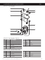
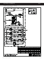
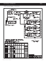
ILLUSTRATED PARTS/RECOMMENDED PARTS IP66
8$ø5"/,"44&.#-:*--6453"5&%1"3543&$0..&/%&%1"354 /$
ITEM # PART # DESCRIPTION
1 WC-54117 TANK, COMPLETE 1450W 120V CAFÉ
2 WC-54125-101 COVER, W/A HEATING TANK CAFE
3 WC-43062 GASKET, TANK LID
4 WC-5418 CLIP, RESET THERMOSTAT GEN USE
5 WC-917-04
ELEMENT, HEATING 1.45KW 120V W/JAM NUTS &
SILICONE O-RING
6 WC-1438-101 SENSOR, TEMPERATURE TANK
7 WC-4394
GUARD, SHOCK/HEATING ELEMENT FOR SINGLE
HEATING ELEMENT
ITEM # PART # DESCRIPTION
3 WC-43062 GASKET, TANK LID
5 WC-917-04
ELEMENT, HEATING 1.45KW 120V W/JAM NUTS &
SILICONE O-RING
6 WC-1438-101 SENSOR, TEMPERATURE TANK
7 WC-4394
GUARD, SHOCK/HEATING ELEMENT FOR SINGLE
HEATING ELEMENT
WC-54117 - Recommended Parts to Stock
ITEM # PART # DESCRIPTION
8WC-521
THERMOSTAT, HI-LIMIT SPST 120V 15A AUTO-RE-
SET
9 WC-2627
BUSHING, CONICAL .583ID X .945 OD .886LG
12mm GEN USE
10 WC-2628
BUSHING, CONICAL.469 ID X .945 OD X .986 LG
8mm GEN USE
ITEM # PART # DESCRIPTION
8WC-521
THERMOSTAT, HI-LIMIT SPST 120V 15A AUTO-RE-
SET
9 WC-2627
BUSHING, CONICAL .583ID X .945 OD .886LG 12mm
GEN USE
10 WC-2628
BUSHING, CONICAL.469 ID X .945 OD X .986 LG
8mm GEN USE
11 WC-29042 HOSE, VENTILATION HEATING TANK CAFÉ
WC-54117 - Tank Assembly
2
3
6
7
4
8
1
5
9
WC-54117 - Tank Assembly - Parts List
11
10
Page is loading ...
Page is loading ...
Page is loading ...
Page is loading ...
Page is loading ...
Page is loading ...
Page is loading ...
-
 1
1
-
 2
2
-
 3
3
-
 4
4
-
 5
5
-
 6
6
-
 7
7
-
 8
8
-
 9
9
-
 10
10
-
 11
11
-
 12
12
-
 13
13
-
 14
14
-
 15
15
-
 16
16
-
 17
17
-
 18
18
-
 19
19
-
 20
20
-
 21
21
-
 22
22
-
 23
23
-
 24
24
-
 25
25
-
 26
26
-
 27
27


Curtis CAFE1DB10A000 User guide
- Category
- Coffee making accessories
- Type
- User guide
- This manual is also suitable for
Ask a question and I''ll find the answer in the document
Finding information in a document is now easier with AI
Related papers
-
Curtis CAFE0AP10A000 User manual
-
Curtis G4GEMS63A1000 User guide
-
Curtis GEMTS19A1000 User guide
-
-
-
-
-
-
Curtis TPC15S10A1100, TPC15S63A1100, TPC15T10A1100 User guide
-
Other documents
-
Newco ak 1 Operating instructions
-
 Wilbur Curtis Company CAFE 2DBS User manual
-
KINGSWOOD KWC60X User guide
-
Newco GXF1-30 Operating instructions
-
Cecilware APT18P Operating instructions
-
Kärcher CVU 120V Operating Instructions Manual
-
 Newco NKLP4 User guide
-
 Wilbur Curtis Company RU-600 User manual
-
Coffee Queen V-2 User manual
-
Bloomfield Decanter Style 8572D3F Owner's manual


