Page is loading ...

MODELS: H27E-NG11 Natural Gas H27E-LP11 Propane
H27 Direct Vent Gas Fireplace
Owners &
Installation Manual
www.hampton-fire.com
FPI FIREPLACE PRODUCTS INTERNATIONAL LTD. 6988 Venture St., Delta, BC Canada, V4G 1H4
920-043
05.29.19
Tested by:
WARNING
FIRE OR EXPLOSION HAZARD
Failure to follow safety warnings exactly could result in serious
injury, death, or property damage.
- Do not store or use gasoline or other flammable vapors and liquids in the vicinity of this or any other
appliance.
- WHAT TO DO IF YOU SMELL GAS
• Do not try to light any appliance.
• Do not touch any electrical switch: do not use any phone in your building.
Leave the building immediately.
• Immediately call your gas supplier from a neighbour's phone. Follow the gas supplier's
instructions.
• If you cannot reach your gas supplier, call the fire department.
- Installation and service must be performed by a qualified installer, service agency or the gas supplier.
Installer: Please complete the details on the back cover
and leave this manual with the homeowner.
Homeowner: Please keep these instructions for future reference.
Certified to/Certifié pour: CSA 2.17-2017
ANSI Z21.88-2017
CSA 2.33-2017

2 | Hampton
®
H27E-11 Direct Vent Freestanding Gas Stove
HAMPTON
®
Direct Vent Freestanding Gas Stove
To the New Owner:
Congratulations!
You are the owner of a state-of-the-art Hampton
®
Gas Stove by REGENCY FIREPLACE PRODUCTS. The H27E-11 is a
hand crafted appliance and has been designed to provide you with all the warmth and charm of a wood fireplace at
the flick of a switch. The model H27E-11 has been approved by Warnock Hersey/Intertek for both safety and efficiency.
As it also bears our own mark, it promises to provide you with economy, comfort and security for many trouble free
years to follow. Please take a moment now to acquaint yourself with these instructions and the many features of your
Hampton
®
Stove.
H27 Product Video

Hampton
®
H27E-11 Direct Vent Freestanding Gas Stove | 3
table of contents
On Demand Pilot Light (seven day safety timer)
Important information if using the appliance in CPI (continuous pilot mode) only
This appliance is a ProFlame 2 system fitted with the “On Demand” Pilot, a safety feature which will shut down the gas valve completely
by extinguishing the pilot light in the event of a continuous full seven days of inactivity.
This only applies if the CPI (continuous pilot) switch is in the “on” position in your remote control transmitter.
Each time the main burner shuts down, manually or through the call from the thermostat, the seven day timer starts again.
The seven day inactivity timer is controlled within the circuit board. Therefore, if in CPI mode and when the pilot light is extinguished
after seven straight days of inactivity, the CPI setting on the remote control transmitter will remain in the “CPI” (continuous pilot) position.
Therefore, all that is required to relight the pilot would be to press the on/off button on the remote control transmitter from “on” to “off” and
back to “on”. Once the pilot has re-established operation will resume as normal. There is no requirement to do anything with the IPI/CPI
mode on the remote control transmitter.
If the unit never goes as long as seven full days without a call for heat, the pilot will remain lit until it is manually shut-off.
If the unit is being operated in IPI (intermittent pilot) mode, neither the above instructions nor the seven day timer will apply.
See the instructions in this manual and on the Lighting Instructions plate on the appliance to light or re-light the pilot.
General Safety Information ..........................................14
Installation Checklist ....................................................14
Clearances to Combustibles ........................................15
Locating Your Gas Stove..............................................15
Manufactured Mobile Home Additional Requirements 15
Combustion and Ventilation Air ....................................15
Accent Light Bulb Install ..............................................15
Optional Fan Installation ..............................................16
Glass Front Removal / installation ...............................17
Optional Wall Thermostat Installation ..........................18
Venting Introduction .....................................................19
Installation Precautions ...............................................19
Safety Precautions for the Installer ..............................19
Vent Restrictor Position ...............................................19
Rotating 45
o
Elbow ......................................................19
Exterior Vent Terminal Locations .................................20
4” x 6-5/8” Rigid Pipe Cross Reference Chart .............21
Rigid Pipe Venting Systems .........................................23
Venting Arrangements .................................................24
Vertical Termination with Co-linear Flex System ..........27
DV Stove Horizontal Vent Kit Installation .....................28
On Demand Pilot Light (seven day safety timer) ...........3
Copy of the Safety Decal ...............................................4
Unit Dimensions with Vertical Venting ............................6
Unit Dimensions with Horizontal Venting .......................6
Important Message ......................................................7
Specifications ................................................................7
Information for Mobile / Manufactured Homes After First
Sale ...............................................................................7
Before You Start .............................................................7
Lighting / Shutdown Procedure .....................................8
Copy of the Lighting Plate Instructions .........................9
Proflame II Remote Control Operating Instructions ....10
Warranty ......................................................................52
Residential and Manufactured Homes/Mobile Homes 30
Dura-Vent Termination Kit ............................................31
Horizontal terminations ................................................32
Vertical Terminations ...................................................33
Converting Class-A Metal Chimney to Direct Vent System
.....................................................................................35
Cathedral Ceilings .......................................................36
High Elevation ..............................................................36
Gas Connection ...........................................................36
Aeration Adjustment ....................................................37
Gas Pipe Pressure Testing ..........................................37
885 S.I.T. Valve Description .........................................37
Conversion Kit from NG to LP .....................................38
Log Set Installation ......................................................39
Optional Wall Thermostat ...........................................41
Remote/Receiver Coding ............................................41
Manual Operation (No Remote) ..................................41
Final Check ..................................................................41
Back Up Battery...........................................................41
Wiring Diagram Without Thermostat ............................42
Wiring Diagram With Thermostat .................................43
First Fire ......................................................................44
Operating Instructions .................................................44
Operation Using an Optional Wall Thermostat ............44
Lighting / Shutdown Procedure ...................................45
Copy of the Lighting Plate Instructions .......................46
Normal Operating Sounds of Gas Appliances .............47
Maintenance Instructions ............................................47
Flame Pattern ..............................................................47
General Vent Maintenance ..........................................48
Log Replacement ........................................................48
Glass Replacement .....................................................48
Fan Maintenance .........................................................48
Safety Screen Removal / Installation ...........................49
Valve Assembly Replacement .....................................49
Accent Light Bulb Replacement ..................................49
Main Assembly ............................................................50
Burner & Log Assembly ...............................................51
Warranty ......................................................................52
Owner's Information
Installer's Information

4 | Hampton
®
H27E-11 Direct Vent Freestanding Gas Stove
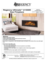
safety decal
This is a copy of the label that accompanies
each Direct Vent Freestanding Gas Stove. We
have printed a copy of the contents here for
your review.
Copy of Safety Label
NOTE: Hampton
®
units are constantly being
improved. Check the label on the unit and if
there is a difference, the label on the unit is
the correct one.
For the State of Massachusetts, installation
and repair must be done by a plumber or
gas fitter licensed in the Commonwealth
of Massachusetts.
For the State of Massachusetts, flexible
connectors shall not exceed 36 inches
in length.
For the State of Massachusetts, the ap-
pliances individual manual shut-off must
be a t-handle type valve.
The State of Massachusetts requires the
installation of a carbon monoxide alarm
in accordance with NFPA 720 and a CO
alarm with battery back up in the same
room where the gas appliance is installed.
5" WC/C.E. (1.25 kPa)
3.5" WC/C.E. (0.87 kPa)
1.6" WC/C.E. (0.40 kPa)
11" WC/C.E. (2.74 kPa)
10" WC/C.E. (2.49 kPa)
6.4" WC/C.E. (1.59 kPa)
Minimum supply pressure
Manifold pressure High
Manifold pressure Low
Minimum supply pressure
Manifold pressure High
Manifold pressure Low
DUPLICATE SERIAL NO.
DO NOT REMOVE THIS LABEL /
NE PAS ENLEVER CETTE ÉTIQUETTE
514
514
FPI Fireplace Products International Ltd. Delta, BC, Canada
Made in Canada/Fabriqué au Canada
Minimum Clearances to Combustibles/Dégagements minimaux aux matériaux combustibles
C 2" / 50mm
E 2"/50mm
A 6"/150mm
B 3"/75mm
Minimum ceiling height from top of unit:24"/610mm
Hauteur du plafond min. depuis le dessus de
l'appareil : 24"/610mm
Minimum clearance of Vent Terminal
to Outside Corner & Inside Corner:
with AstroCap 6"/150mm
with Dura-Vent Cap 12"/300mm
Serial No./ No de série
Maximum Input
Minimum Input
Orifice size
Altitude
Maximum Input
Minimum Input
Orifice size
Altitude
FACTORY EQUIPPED FOR NATURAL GAS Model:H27E-NG11
FACTORY EQUIPPED FOR PROPANE GAS Model:H27E-LP11
Pression d'alimentation minimale
Pression manifold lev e é é
Pression manifold basse
Pression d'alimentation minimale
Pression lev e manifold é é
Pression manifold basse
Left Side Wall
Right Side Wall
Horizontal
Pipe
25,000 Btu/h (7.32 Kw/h)
18,000 Btu/h (5.28 Kw/h)
#42 DMS (2.37mm)
0-4500 ft/pi (0-1372m)
22,000 Btu/h (6.45 Kw/h)
17,500 Btu/h (5.13 Kw/h)
#54 DMS (1.4mm)
0-4500 ft/pi (0-1372m)
D bit calorifique maximalé
D bit calorifique minimalé
Taille de l'orifice
Altitude
D bit calorifique maximalé
D bit calorifique minimalé
Taille de l'orifice
Altitude
Left Side Wall
Right Side Wall
Vertical
Pipe
See Manual for details
Model/Modèle:
H27E-NG11
Model/Modèle:
H27E-LP11
Part #: 920-077
Colour: Everything black on grey except for items indicated as being printed in red.
Size: Printed at 100% 6.023’’W
Material: 2 ml silver matt polyester (DPM SMS)
*Printer: Start number sequence @ 044000001
MAY BE INSTALLED IN MANUFACTURED (MOBILE) HOMES AFTER FIRST SALE.
4001172
Listed: VENTED GAS FIREPLACE HEATER /
FOYER AU GAZ À ÉVACUATION
Certified to/Certifi : CSA 2.17-2017é
ANSI Z21.88-2017
CSA 2.33-2017
This appliance must be installed in accordance with local codes, if any; if none, follow the National Fuel Gas Code, ANSI Z223.1, or
Natural Gas and Propane Installation Code, CSA B149.1.
This appliance must be installed in accordance with the Standard CAN/CSA Z240 MH, Mobile Housing, in Canada, or with the Manufactured
Home Construction and Safety Standard, Title 24 CFR, Part 3280, in the United States, or when such a standard is not applicable,
ANSI/NCSBCS A225.1/NFPA 501A, Manufactured Home Installations Standard or ANSI A119.2 ou NFPA 501C Standard for Recreational
Vehicles
This appliance is only for use with the type of gas indicated on the rating plate and may be installed in an aftermarket, permanently located,
manufactured (mobile) home where not prohibited by local codes. See owner's manual for details. Optional Fan Kit (Part # 357-917)
Installer l'appareil selon les codes ou règlements locaux, ou, en l'absence de tels règlements, selon les codes d'installation ANSI Z223.1,
National Fuel Gas Code ou CSA-B149.1 en vigueur.
Installer l'appareil selon la norme CAN/CSA-Z240, Série MM, Maison mobiles ou CAN/CSA-Z240 VC, Véhicules de camping, ou la norme 24
CFR Part 3280, Manufactured Home Construction and Safety Standard. En l’absence de telles normes, suivre la norme ANSI/NCSBCS
A225.1/NFPA 501A, Manufactured Home Installations Standard, ou ANSI A119.2 ou NFPA 501C Standard for Recreational Vehicles.
Cet appareil doit être utilisé uniquement avec le type de gaz indiqué sur la plaque signalétique. Cet appareil peut être installé dans une maison
préfabriquée ou mobile (É.-U. seulement) installée à demeure si les règlements locaux le permettent. Voir le manuel d'utilisation pour plus de
détails. Kit du ventilateur en option (Pièce n°357-917).
This vented gas fireplace heater is not for use with air filters. Ne pas utiliser de filtre à air avec ce foyer au gaz à évacuation.
VENTED GAS FIREPLACE HEATER - NOT FOR USE WITH SOLID FUELS.
NE PAS UTILISER AVEC UN COMBUSTIBLE SOLIDE. FOYER AU GAZ À ÉVACUATION -
For Use Only with Barrier (Part # 357-007) Follow installation instructions.
Utiliser uniquement avec l’écran (n°357-007) Suivre les instructions d'installation.
ELECTRICAL SUPPLY/ALIMENTATION ÉLECTRIQUE :115V_60HZ less than/moins de 2 AMP
APPAREIL FONCTIONNANT AU GAZ NATUREL
APPAREIL FONCTIONNANT AU GAZ PROPANE
Refer to Intertek's Directory of Building Products for detailed information.
Pour plus de détails, se reporter au Répertoire des produits de construction de Intertek.
920-077
CSA P.4.1 Fireplace Efficiency (FE) /
Efficacité énergétique des foyers (EEF) CSA P.4.1
Natural Gas / Gaz naturel 61.22%
Propane Gas / Gaz propane 63.07%
CANADIAN ENERGY
PERFORMANCE
VERIFIED
RENDEMENT
ÉNERGÉTIQUE
VÉRIFIÉ
EP5011169
Decal Location
Fold down access door, and then remove two screws
as shown below
With the panel removed, the gas valve will be visible.
The rating plate will be attached to a black chain
located under the IFC.
DO NOT REMOVE THE DECAL FROM THE UNIT.

Hampton
®
H27E-11 Direct Vent Freestanding Gas Stove | 5
requirements
installer's information
5.08: Modifications to NFPA-54, Chapter 10
(2) Revise 10.8.3 by adding the following additional requirements:
(a) For all side wall horizontally vented gas fueled equipment installed in every dwelling, building or structure used in whole or in part for
residential purposes, including those owned or operated by the Commonwealth and where the side wall exhaust vent termination is less than
seven (7) feet above finished grade in the area of the venting, including but not limited to decks and porches, the following requirements shall
be satisfied:
1. INSTALLATION OF CARBON MONOXIDE DETECTORS. At the time of installation of the side wall horizontal vented gas fueled
equipment, the installing plumber or gasfitter shall observe that a hard wired carbon monoxide detector with an alarm and battery back-up is
installed on the floor level where the gas equipment is to be installed. In addition, the installing plumber or gasfitter shall observe that a battery
operated or hard wired carbon monoxide detector with an alarm is installed on each additional level of the dwelling, building or structure
served by the side wall horizontal vented gas fueled equipment. It shall be the responsibility of the property owner to secure the services of
qualified licensed professionals for the installation of hard wired carbon monoxide detectors
a. In the event that the side wall horizontally vented gas fueled equipment is installed in a crawl space or an attic, the hard wired carbon
monoxide detector with alarm and battery back-up may be installed on the next adjacent floor level.
b. In the event that the requirements of this subdivision can not be met at the time of completion of installation, the owner shall have a period of
thirty (30) days to comply with the above requirements; provided, however, that during said thirty (30) day period, a battery operated carbon
monoxide detector with an alarm shall be installed.
2. APPROVED CARBON MONOXIDE DETECTORS. Each carbon monoxide detector as required in accordance with the above provisions
shall comply with NFPA 720 and be ANSI/UL 2034 listed and IAS certified.
3. SIGNAGE. A metal or plastic identification plate shall be permanently mounted to the exterior of the building at a minimum height of eight
(8) feet above grade directly in line with the exhaust vent terminal for the horizontally vented gas fueled heating appliance or equipment. The
sign shall read, in print size no less than one-half (1/2) inch in size, "GAS VENT DIRECTLY BELOW. KEEP CLEAR OF ALL
OBSTRUCTIONS".
4. INSPECTION. The state or local gas inspector of the side wall horizontally vented gas fueled equipment shall not approve the installation
unless, upon inspection, the inspector observes carbon monoxide detectors and signage installed in accordance with the provisions of 248 CMR
5.08(2)(a)1 through 4.
(b) EXEMPTIONS: The following equipment is exempt from 248 CMR 5.08(2)(a)1 through 4:
1. The equipment listed in Chapter 10 entitled "Equipment Not Required To Be Vented" in the most current edition of NFPA 54 as adopted by
the Board; and
2. Product Approved side wall horizontally vented gas fueled equipment installed in a room or structure separate from the dwelling, building or
structure used in whole or in part for residential purposes.
(c) MANUFACTURER REQUIREMENTS - GAS EQUIPMENT VENTING SYSTEM PROVIDED. When the manufacturer of Product
Approved side wall horizontally vented gas equipment provides a venting system design or venting system components with the equipment, the
instructions provided by the manufacturer for installation of the equipment and the venting system shall include:
1. Detailed instructions for the installation of the venting system design or the venting system components; and
2. A complete parts list for the venting system design or venting system.
(d) MANUFACTURER REQUIREMENTS - GAS EQUIPMENT VENTING SYSTEM NOT PROVIDED. When the manufacturer of a
Product Approved side wall horizontally vented gas fueled equipment does not provide the parts for venting the flue gases, but identifies
"special venting systems", the following requirements shall be satisfied by the manufacturer:
1. The referenced "special venting system" instructions shall be included with the appliance or equipment installation instructions; and
2. The "special venting systems" shall be Product Approved by the Board, and the instructions for that system shall include a parts list and
detailed installation instructions.
(e) A copy of all installation instructions for all Product Approved side wall horizontally vented gas fueled equipment, all venting instructions,
all parts lists for venting instructions, and/or all venting design instructions shall remain with the appliance or equipment at the completion of
the installation.
MA Code - CO Detector
(for the State of Massachusetts only)

6 | Hampton
®
H27E-11 Direct Vent Freestanding Gas Stove
dimensions
Unit Dimensions with Vertical Venting
Unit Dimensions with Horizontal Venting
(452 mm)
17 13/16”
(452 mm)
ALL PICTURES / DIAGRAMS SHOWN THROUGHOUT THIS MANUAL ARE FOR ILLUSTRATION PURPOSES ONLY.
ACTUAL PRODUCT MAY VARY DUE TO PRODUCT ENHANCEMENTS.

Hampton
®
H27E-11 Direct Vent Freestanding Gas Stove | 7
installation
Before You Start
Safe installation and operation of this appliance
requires common sense, however, we are required
by the Canadian Safety Standards and ANSI
Standards to make you aware of the following:
CLOTHING OR OTHER FLAMMABLE
MATERIAL SHOULD NOT BE PLACED
ON OR NEAR THE APPLIANCE.
CHILDREN AND ADULTS SHOULD BE
ALERTED TO THE HAZARDS OF HIGH
SURFACE TEMPERATURES, ESPE-
CIALLY THE FIREPLACE GLASS, AND
SHOULD STAY AWAY TO AVOID BURNS
OR CLOTHING IGNITION.
INSTALLATION AND REPAIR SHOULD
BE DONE BY AN AUTHORIZED
SERVICE PERSON. THE APPLIANCE
SHOULD BE INSPECTED BEFORE
USE AND AT LEAST ANNUALLY BY A
PROFESSIONAL SERVICE PERSON.
MORE FREQUENT CLEANING MAY
BE REQUIRED DUE TO EXCESSIVE
LINT FROM CARPETING, BEDDING
MATERIAL, ETC. IT IS IMPERATIVE THAT
CONTROL COMPARTMENTS, BURNERS
AND CIRCULATING AIR PASSAGEWAYS
OF THE APPLIANCE BE KEPT CLEAN.
DUE TO HIGH TEMPERATURES, THE
APPLIANCE SHOULD BE LOCATED
OUT OF TRAFFIC AND AWAY FROM
FURNITURE AND DRAPERIES.
WARNING: FAILURE TO INSTALL THIS
APPLIANCE CORRECTLY WILL VOID
YOUR WARRANTY AND MAY CAUSE A
SERIOUS HOUSE FIRE.
YOUNG CHILDREN SHOULD BE CARE-
FULLY SUPERVISED WHEN THEY ARE
IN THE SAME AREA AS THE APPLI-
ANCE. TODDLERS, YOUNG CHILDREN
AND OTHERS MAY BE SUSCEPTIBLE
TO ACCIDENTAL CONTACT BURNS. A
PHYSICAL BARRIERS IS RECOMMEND-
ED IF THERE ARE AT RISK INDIVIDUAL
IN THE HOUSE. TO RESTRICT ACCESS
TO A FIREPLACE OR STOVE, INSTALL
AN ADJUSTABLE SAFETY GATE TO
KEEP TODDLERS, YOUNG CHILDREN
AND OTHER AT RISK INDIVIDUALS OUT
OF THE ROOM AND AWAY FROM HOT
SURFACES.
A BARRIER DESIGNED TO REDUCE
THE RISK OF BURNS FROM THE HOT
VIEWING GLASS IS PROVIDED WITH
THIS APPLIANCE AND SHALL BE
INSTALLED FOR THE PROTECTION
OF CHILDREN AND OTHER AT-RISK
INDIVIDUALS
IF THE BARRIER BECOMES DAMAGED,
THE BARRIER SHALL BE REPLACED
WITH THE MANUFACTURER'S BARRIER
FOR THIS APPLIANCE.
ANY SAFETY SCREEN, GUARD, OR
BARRIER REMOVED FOR SERVICING
AN APPLIANCE MUST BE REPLACED
PRIOR TO OPERATING THE APPLIANCE.
Important Message
SAVE THESE INSTRUCTIONS
The Direct Vent Freestanding Gas Stove must
be installed in accordance with these instructions.
Carefully read all the instructions in this manual first.
Consult the building authority having jurisdiction
to determine the need for a permit prior to starting
the installation.
Note: Failure to follow the instructions
could cause a malfunction of the
heater which could result in death,
serious bodily injury, and/or prop-
erty damage. Failure to follow these
instructions may also void your fire
insurance and/or warranty.
Note: These instructions take precedence
over Simpson Dura-Vent instruc-
tions.
Specifications
Fuels: H27E-NG11 is approved for use with
natural gas.
H27E-LP11 is approved for use with
liquefied petroleum gases (propane).
Electrical: 120V A.C. system.
Optional Circulation Fan:
Variable speed, 125/75.
Log Sets: Ceramic fibre, 4 per set.
Vent System: Coaxial (6-5/8" outer / 4" inner liner)
rigid flue and termination cap.
Information for Mobile /
Manufactured Homes After First
Sale
This Hampton
®
product has been tested and listed
by ITS Testing Services as a Direct Vent Wall Fur-
nace to the following standards:
CSA-2.17-2017, and ANSI Z21.88-2017/CSA
2.33-2017.
This Direct Vent System Appliance must be installed
in accordance with the manufacturer's installation
instructions and the Manufactured Home Construc-
tion and Safety Standard, Title 24 CFR, Part 3280,
or the current Standard of Fire Safety Criteria
for Manufactured Home Installations, Sites, and
Communities ANSI/NFPA 501A, and with CAN/
CSA Z240-MH Mobile Home Standard in Canada.
This appliance installation must comply with the
manufacturer's installation instructions and local
codes, if any. In the absence of local codes follow
the current National Fuel Gas Code, ANSI Z223.1
and the current National Electrical Code ANSI/NFPA
70 in the U.S.A., and the current CAN/CGA B149
Gas Installation Code and the current Canadian
Electrical Code CSA C22.1 in Canada.
This Hampton
®
Mobile/Manufactured Home
Listed appliance comes factory equipped with
a means to secure the unit.
This Hampton
®
Mobile/Manufactured Home
listed appliance comes equipped with a dedi-
cated #8 ground lug to which an 18 gauge
copper wire from the steel chassis ground
must be attached.
This appliance may only be installed in an
aftermarket permanently located, manufac-
tured (USA only) or mobile home, where
not prohibited by local codes.
This appliance is only for use with the type
of gas indicated on the rating plate. This
appliance is not convertible for use with
other gases, unless a certified kit is used.

8 | Hampton
®
H27E-11 Direct Vent Freestanding Gas Stove
owner's information
IMPORTANT: The remote control system supplied with this appliance has
several options for starting/operating the appliance using the power button
and ON/OFF key on the hand held transmitter.
Prior to operating this appliance, please read the remote control operating
instructions (packaged with remote control) to understand how to operate
this remote control system.
1. Ensure the Main switch is in the ON position and/or the battery holder
switch is in the Remote position.
2. Press and release the ON/OFF button on the remote handheld transmit-
ter (see Diagram 2). An audible beep should be heard from the receiver.
Note: The first try for ignition will last approximately 60 seconds. If there is no
flame ignition (rectification) the board will stop sparking for approximately
35 seconds. After wait time , the board will start second try for ignition by
sparking for approximately 60 seconds . If there is still no positive ignition
the board will go into lock out.
The system will need to be reset as follows:
a) Wait 5 minutes - turn the system off by pressing the ON/OFF button on
the remote.
b) After approximately 2 seconds turn on ON/OFF switch or press ON/OFF
button if using optional remote.
c) Repeat step 2.
Shutdown Procedure
1. Press the ON/OFF button on the remote
ON/OFF
Button
Diagram 2
2. If service is to be performed- you must disconnect power and shut off gas
to the unit.
Remote shown in Manual Mode on Hi
3. After approximately 4 seconds the spark ignition system will spark for 60
seconds to light the main burner.
4. The unit will turn on.
Lighting Procedure
Fan Operation:
The optional fan can be operated by using the remote control supplied with
this unit. See remote control instructions.
Note:
In thermostat mode: When the appliance is turned on, the fan will not come
on for the first 5 minutes (if fan is turned on). When the appliance is turned off
the fan will not turn off for 12 minutes (if in on position)
Manual mode: Fan will turn on and off immediately using the remote control
transmitter if the fan function is in the "on" position.
Continuous Pilot/Intermittent Pilot (CPI/IPI) selection
See remote control instructions for details.

Hampton
®
H27E-11 Direct Vent Freestanding Gas Stove | 9
owner's information
Copy of the Lighting Plate Instructions
919-535
Part #: 919-535
Colours: Black on Grey, except
for parts indicated as being
Red.
Size: 100%
w- 5.16"
h- 10.3"
Mar 25/15: Created decal
A) This appliance is equipped with an ignition device which automatically lights the pilot.
Do not try to light the pilot by hand.
B) BEFORE OPERATING smell all around the appliance area for gas. Be sure to smell next to the fl oor
because some gas is heavier than air and will settle on the fl oor.
WHAT TO DO IF YOU SMELL GAS
- Do not try to light any appliance.
- Do not touch any electric switch, do not use any phone in your building.
- Immediately call your gas supplier from a neighbours phone. Follow the gas supplier’s instructions.
- If you cannot reach your gas supplier, call the fi re department.
C) Do not use this appliance if any part has been under water. Immediately call a qualifi ed service
technician to inspect the appliance and replace any part of the control system and any
gas control which has been underwater.
A) Cet appareil est muni d’un dispositif d’allumage qui allume automatiquement la veilleuse.
Ne tentez pas d’allumer la veilleuse manuellement.
B) AVANT DE FAIRE FONCTIONNER, renifl ez tout autour de l’appareil pour déceler une odeur
de gaz. Renifl ez près du plancher, car certains gaz sont plus lourds que l’air et peuvent
s’accumuler au niveau du sol.
QUE FAIRE SI VOUS SENTEZ UNE ODEUR DE GAZ :
• Ne tentez pas d’allumer d’appareil
• Ne touchez à aucun interrupteur; ne vous servez pas des téléphones se trouvant dans le
bâtiment.
• Appelez immédiatement votre fournisseur de gaz depuis un voisin. Suivez les instructions du fournisseur.
• Si vous ne pouvez rejoindre le fournisseur, appelez le service incendie.
C) N’utilisez pas cet appareil s’il a été plongé dans l’eau, même partiellement. Faites inspecter l’appareil par un tech-
nicien qualifi é et remplacez toute partie du système de contrôle et toute commande qui ont été plongés dans l’eau.
DO NOT REMOVE THIS INSTRUCTION PLATE
TO TURN OFF GAS APPLIANCE
This appliance must be installed in accordance with local codes, if any;
if none, follow the National Fuel Gas Code, ANSI Z223.1/NFPA 54, or
Natural Gas and Propane Installation Codes, CSA B149.1.
CAUTION: Hot while in operation. Do not touch. Severe Burns may result. Due to high surface
temperatures keep children, clothing and furniture, gasoline and other liquids having fl ammable
vapors away. Keep burner and control compartment clean. See installation and operating
instructions accompanying appliance.
WARNING: If you do not follow these instructions exactly, a fire or explosion may result
causing property damage, personal injury or loss of life. Improper installation, adjustment,
alteration, service or maintenance can cause injury or property damage. Refer to the owner’s
information manual provided with this appliance. For assistance or additional information
consult a qualified installer, service agency or gas supplier.
AVERTISSEMENT. Quiconque ne respecte pas à la lettre les instructions dans la présente notice
risque de déclencher un incendie ou une explosion entraînant des dommages, des blessures ou
la mort.
Tout défaut d'installation, d'ajustement, de modifi cation, de service ou d'entretien peut provo-
quer des blessures ou des dommages matériels. Reportez-vous au manuel du propriétaire de
l'information fournie avec cet appareil. Pour obtenir de l'aide ou des informations supplémen-
taires consulter un installateur qualifi é, une agence de service ou fournisseur de gaz.
1) Ensure the Main switch is in the ON position and/or the battery holder switch is in the Remote position.
2) Press and release the ON/OFF button on the remote handheld transmitter. An audible beep should be
heard from the receiver.
3) After approximately 4 seconds the spark ignition system will spark for 60 seconds to light the main burner.
4) The unit will turn on.
Note: The fi rst attempt to ignition will last approximately 60 seconds. If there is no fl ame ignition (rectifi ca-
tion) the board will stop sparking for approximately 35 seconds. After this wait time, the board will start a
second try for ignition by sparking for approximately 60 seconds. If there is still no positive ignition after the
second attempt the board will go into lock out.
The system will need to be reset as follows (after going into lock out mode):
a) Wait 5 minutes - turn the system off by pressing the ON/OFF button on the remote.
b) After approximately 2 seconds press the ON/OFF button again.
c) Unit will repeat step 2.
1) S’assurer que l’interrupteur principal est sur ON et/ou que l’interrupteur du support de piles est en posi-
tion télécommande.
2) Appuyer sur la touche ON/OFF de la télécommande et relâcher. Un bip se fera entendre depuis le récep-
teur.
3) Après environ 4 secondes, le système d'allumage produira des étincelles pendant 60 secondes pour al-
lumer le brûleur principal.
4) L'appareil s’allume.
Remarque : Au premier allumage, le système tente d’allumer les fl ammes pendant 60 secondes. Si l’essai
est infructueux, le système fait une pause de 35 secondes. C’est ce qu'on appelle l'étape de rectifi cation.
Ce délai écoulé, le système tente à nouveau d'allumer les fl ammes en produisant des étincelles pendant 60
secondes. Si les fl ammes ne s’allument toujours pas, le système se met en mode verrouillage.
Il faut alors le réinitialiser en suivant les étapes ci-dessous (pour le déverrouiller) :
a) Attendre 5 minutes et éteindre l’appareil en appuyant sur la touche ON/OFF de la télécom-
mande.
b) Attendre 2 secondes et appuyer encore une fois sur la touche ON/OFF.
c) L'appareil répète l'étape 2.
1) Press the ON/OFF button on the remote.
2) If service is to be performed–you must disconnect power and shut off gas to the unit.
1)
Appuyer sur la touche ON/OFF de la télécommande.
2) En cas d'entretien, débrancher l'alimentation électrique et couper le gaz.
LIGHTING INSTRUCTIONS
FOR YOUR SAFETY READ BEFORE LIGHTING

10 | Hampton
®
H27E-11 Direct Vent Freestanding Gas Stove
owner's information
919-829
09.29.17
PROFLAME II REMOTE CONTROL OPERATING INSTRUCTIONS
WARNING: THE TRANSMITTER AND RECEIVER ARE RA‑
DIO FREQUENCY DEVICES. PLACING THE RECEIVER IN
OR NEAR METAL MAY SERVERELY REDUCE THE SIGNAL
The Proflame 2 Transmitter provides for controlling the following hearth
appliance functions:
1. Main Burner On/Off
2. Main Burner flame modulation (6 levels)
3. Choice of standing or intermittent pilot (CPI/IPI)
4. Thermostat and Smart thermostat functions
5. Accent light modulation (6 levels)**
6. Split flow valve**
7. Comfort Fan speed modulation (6 levels)**
** This feature is not available on all models.
IMPORTANT:The Proflame Transmitter 2 is an integrated part of the
Proflame 2 System, which consists of these elements:
• Proflame 2 Transmitter, to be used in conjunction with:
• Integrated Fireplaces Control (Proflame 2 IFC)
The Proflame Transmitter uses a streamline design with a simple button
layout and informative LCD display (Fig. 1). A Mode Key is provided to
index between the features and a Thermostat Key is used to turn on/off
or index through Thermostat functions (Fig. 1 & 2). Additionally, a Key
Lock feature is provided (Fig. 22).
Figure 1: Proflame Transmitter
Figure 2: Transmitter LCD Display
TECHNICAL DATA
REMOTE CONTROL
Supply Voltage 4.5V (three 1.5V AAA batteries)
Ambient temperature
ratings
0 - 50
o
C (32 - 122
o
F)
Radio Frequency 315 MHZ
ATTENTION!
- Turn “OFF” the main gas supply of the appliance during installation or
maintenance of the Receiver device.
- Turn “OFF” main gas supply to the appliance prior to removing or rein-
serting the batteries.
- In case of remote control malfunction, turn off the IFC device using the
"ON/OFF" main switch.
- For installation / maintenance, switch off the IFC device removing main
power supply plug.
OPERATING PROCEDURE
Initializing the System for the first time
Power the receiver. Activate the procedure of the receiver address pro-
gramming, see the receiver instruction (*). The Receiver will “beep” three
(3) times to indicate that it is ready to synchronize with a Transmitter. Install
the 3 AAA type batteries in the Transmitter battery bay, located on the
base of the Transmitter. (fig. 3) With the batteries already installed in the
Transmitter, push the On button. The Receiver will “beep” four times to
indicate the Transmitter’s command is accepted and sets to the particular
code of that Transmitter. The system is now initialized.
(*) The receiver may be independent or integral to the IFC hearth ap-
pliance control module. The receiver instruction may not be indepen-
dent when part of the IFC.
Figure 3: Battery Compartment
4
PROFLAM
E 2
TRANSMI
TTER
USE
ANDINST
AL
L
The Proflame Remote Control System consists of three elements:
1. Proflame Transmitter.
2. Proflame Receiver and a wiring harness to connect the Receiver to the gas valve, stepper
motor and Fan Control Module.
3. Proflame Fan Control Module (FCM)
The Proflame Transmitter uses a streamline design with a simple button layout and informative
LCD display (Fig. 1).
The Transmitter is powered by 3 AAA type batteries.
A Mode Key is provided to Index between the features and a Thermostat Key is used to turn on/
off or index through Thermostat functions (Fig. 1 & 2).
TRANSMITTER (Remote Control with LCD Display)
SYSTEM DESCRIPTION
Fig. 1: PROFLAME Transmitter.
Low battery alarm
Child safety lock-out
Room
Temperature
Aux ON
Set Point
Temperature/Level/State
Flame ON
Thermostat OFF/
ON/SMART
Fan
Fig. 2: Transmitter LCD display.
Transmission
Turn on the Appliance
With the system OFF, press the ON/OFF Key on the
Transmitter. The Transmitter display will show some other
active Icons on the screen. At the same time the Receiver
wil activate the appliance. A single “beep” from the
Receiver will confirm reception of the command.
Turn off the Appliance
With the system ON, press the ON/OFF Key on the
Transmitter. The Transmitter LCD display will only show
the room temperature (Fig. 6). At the same time the
Receiver will turn off the appliance. A single “beep” from
the Receiver confirms reception of the command.
Fig. 6: Remote Control display.
3 Positions Slider
Fig. 4: Proflame Receiver body.
PRG Key
Fig3: Battery
compartment.
Fig. 4: Remote Control display in Farenheit. Fig. 5: Remote Control display in Celsius.
9957099_00_nero_mod_05-10-2011.i4 4 05/10/2011 8.36.38
1
proflame II remote control operating Instructions

Hampton
®
H27E-11 Direct Vent Freestanding Gas Stove | 11
owner's information
919-829 09.29.17
Figure 4: Remote Control dis-
play in Farenheit.
Temperature indication Display
With the system in the "OFF" position, press the Thermostat Key and
the Mode Key at the same time. Look at the LCD screen on the transmit-
ter to verify that a C or F is visible to the right of the room temperature
display (Figures 4 & 5).
Figure 5: Remote Control dis-
play in Celsius.
Turn on the Appliance
With the system OFF, press the ON/
OFF Key on the Transmitter. The
Transmitter display will show some
other active Icons on the screen. At
the same time the Receiver wil ac-
tivate the appliance. A single “beep”
from the Receiver will confi rm recep-
tion of the command.
Figure 6: Remote Control
display
Remote-Flame Control
The profl ame has six (6) fl ame levels. With the system on, and the fl ame
level at the maximum in the appliance, pressing the Down Arrow Key
once will reduce the fl ame height by one step until the fl ame is turned off.
The Up Arrow Key will increase the fl ame height each time it is pressed.
If the Up Arrow Key is pressed while the system is on but the fl ame is off,
the fl ame will come on in the high position. ( Fig. 7 & 8 ) A single “beep”
will confi rm reception of the command.
Fig. 7
Fig. 8
Room Thermostat (Transmitter Operation)
The Remote Control can operate as a room thermostat. The thermostat
can be set to a desired temperature to control the comfort level in a room.
To activate this function, press the Thermostat Key (Fig. 1). The Lcd
display on the Tr ansmitter will change to show that the room thermostat
is “ON” and the set temperature is now displayed (Fig. 9). To adjust the
set temperature, press the Up or Down Arrow Keys until the desired set
temperature is displayed on the LCD screen of the Transmitter.
Figure 9 Figure 10
Turn off the Appliance
With the system ON, press the ON/OFF Key on the Transmitter. The
Transmitter LCD display will only show the room temperature (Fig. 6).
At the same time the Receiver will turn off the appliance. A single “beep”
from the Receiver confi rms reception of the command.
2

12 | Hampton
®
H27E-11 Direct Vent Freestanding Gas Stove
owner's information
919-829
09.29.17
Smart Thermostat (Transmitter Operation)
The Smart Thermostat function adjusts the fl ame height in accordance
to the difference
between the set point temperature and the actual room temperatures.
As the room
temperature gets closer to the set point the Smart Function will modulate
the fl ame down.
To activate this function, press the Thermostat Key (Fig. 1) until the word
"SMART" appears to
the right of the temperature bulb graphic (Fig. 11).
To adjust the set temperature, press the Up or Down Arrow Keys until
the desidered set
temperature is displayed on the LCD screen of the Tr ansmitter (Fig. 12).
Note. When Smart Thermostat is activated, manual fl ame height adjust-
ment is disabled.
Figure 12Figure 11: Smart Flame Function
Fan Speed Control**
If the appliance is equipped with a hot air circulating fan, the speed of
the fan can be controlled by the Profl ame system. The fan speed can be
adjusted through six (6) speeds. To activate this function use the Mode Key
(fi g.1) to index to the fan control icon (Fig. 13). Use the Up/Down Arrow
Keys (fi g.1) to turn on, off or adjust the fan speed (fi g. 14). A single “beep”
will confi rm reception of the command.
Figure 13 Figure 14
Remote dimmer control (Light)**
The auxiliary function controls the AUX power outlet by the dimmable
light control. To activate this function use the Mode Key (fi g. 1) to index
to the AUX icon (fi g. 15 & 16).
The intensity of the output can be adjusted through six (6) levels. Use
the Up/Down Arrow Keys (fi g.1) adjust the output level (fi g. 16). A single
“beep” will confi rm reception of the command.
Note: This function is available only with the IFC Control Module.
Figure 15 Figure 16
Split Flow control**
The secondary burner is controlled by the split Flow. To activate this
function use the Mode Key (fi g. 1) to index to the SPLIT FLOW mode
icon (fi g. 17 & 18).
Pressing the Up Arrow Key will activate the secondary burner. Pressing
the Down Arrow Key will turn the secondary burner off. A single “beep”
will confi rm the reception of the command.
Figure 17 Figure 18
3

Hampton
®
H27E-11 Direct Vent Freestanding Gas Stove | 13
owner's information
919-829 09.29.17
Continuous Pilot/Intermittent Pilot (CPI/IPI) selection
Note: Power vent models do not have a Continuous
Pilot option.
With the system in "OFF" position press the Mode Key (fi g. 1) to index
to the CPI mode icon (fi g. 19 & 20).
Pressing the Up Arrow Key will activate the Continuous Pilot Ignition
mode (CPI). Pressing the Down Arrow Key will return to IPI. A single
“beep” will confi rm the reception of the command.
Figure 19 Figure 20
KEY LOCK
This function will lock the keys to avoid unsupervised operation.
To activate this function, press the MODE and UP Keys at the same
time (fi g. 21).
To de-activate this function, press the MODE and UP Keys at the
same time.
Figure 21
LOW BATTERY POWER DETECTION
Transmitter
The life span of the remote control batteries depends on various factors:
quality of the batteries used, the number of ignitions of the appliance,
the number of changes to the room thermostat set point, etc.
When the Tr ansmitter batteries are low, a Battery Icon will appear on the
LCD display of the Transmitter (Fig. 22) before all battery power is lost.
When the batteries are replaced this Icon will disappear.
Figure 22
CPI/IPI SWITCH
This appliances comes equipped with a CPI/IPI switch. The function of
both the CPI/IPI switch are as follows:
Continuous pilot (CPI) - A pilot that when in operation, is intended to
remain continuously ignited until it is manually interrupted.
Intermittent pilot (IPI) - A pilot that is automatically ignited when an ap-
pliance is called on to operate and which remains continuously ignited
during each period of main burner operation. The pilot is automatically
extinguished when each main burner operating cycle is completed. The
mode of the fi replace is easily changed from an intermittent pilot ignition
system (IPI) to a continuous pilot ignition system (CPI) by using remote
control as noted above.
The benefi ts of having as CPI are as follows:
- Keeps venting primed for trouble free start-up under colder weather
conditions or inversions.
- Keeps the unit glass warm, which decreases the amount of condensa-
tion on start-up
-Provides owners with fl exibility to choose a traditional continuous pilot.
The primary benefi t of having the IPI function is a signifi cant savings on
fuel as the pilot will only run when there is a call for heat.
Thermostat Icon: If the thermostat icon is not present on the remote
transmitter, follow instructions noted below
1. Take one or all batteries out (removing one battery will work).
2. Press and hold down the Thermostat button on the remote.
3. Reinstall the 3rd battery while still holding thermostat button down.
4. If you see "Set" the thermostat option is now enabled. If you see "Clr"
the thermostat option is now disabled
5. Repeat the procedure if you did not see the "Set" or "Clr" to remove
or add the option back to the remote.
Enable all other functions if not present on the remote transmitter, follow
instructions noted below:
1. Remove one battery or all batteries (removing one battery will work).
2. Press and hold both the ON/OFF and the MODE button at the same time .
3. Reinstall the 3rd battery while still holding both buttons (keep holding
buttons once 3rd battery is installed, then release the mode button only.
4. The screen will show either "Clr" or "Set" with the 1st mode being
your option to disable or enable.
5. "Clr" will remove the mode by using the up or down arrow while still
holding both buttons (icon will disappear once removed, or icon
will
show up again once added).
6. Use the "Mode" button to move to the next function.
7. "Set" will add that mode by using the up or down arrow while still
holding both buttons (icon will disappear once removed, or icon
will show up again once added) Use the "Mode" button to move
to the next function.
Note: You should never program out the fan (if installed) or CPI/IPI
mode on the remote.
4

14 | Hampton
®
H27E-11 Direct Vent Freestanding Gas Stove
installation
1) Provide adequate clearances for servicing,
proper operation and around the air openings
into the combustion chamber.
2) The appliance must be installed on a flat, solid,
continuous surface (e.g. wood, metal, concrete).
This may be the floor, or it can be raised up
on a platform to enhance its visual impact. The
appliance may be installed on carpeting, tile,
wood flooring or other combustible material,
because the appliance's base extends the full
width and depth of the appliance. The Direct
Vent Freestanding Gas Stove can be installed
in a wide variety of ways and will fit nearly any
room layout. It may be installed in a recessed
position, framed out into the room, or across
a corner.
3) The Direct Vent Freestanding Gas Stove is
approved for alcove installations, which meet
the clearances listed on in the "Clearance to
Combustibles" section. This unit is approved
for manufactured home installations, see
the "Manufactured Mobile Home Additional
Requirements" section and "Venting Arrange-
ments" section for the required vent arrange-
ments. If installed into a manufactured home
the unit must be bolted down to the floor.
4) This appliance is Listed for bedroom instal-
lations when used with a Listed Millivolt Ther-
mostat. Some areas may have further require-
ments, check local codes before installation.
5) This appliance is Listed for Alcove installations,
maintain minimum Alcove clearances as follows,
minimum width of 34-3/4" (882mm), a maximum
depth of 36" (914mm), and minimum ceiling
height of 51" (1295mm) from floor to ceiling.
6) We recommend that you plan your installation on
paper using exact measurements for clearances
and floor protection before actually installing this
appliance. Have a qualified building inspector
review your plans before installation.
General Safety
Information
1) The appliance installation must conform with
local Canadian Electrical Code.
2) The appliance when installed, must be electri-
cally grounded in accordance with local codes,
or in the absence of local codes with the current
National Electrical Code, ANSI/NFPA 70 or CSA
C22.1 Canadian Electrical Code.
3) The appliance should be inspected for shipping
damage before use and serviced annually by
a professional service person. More frequent
cleaning may be required due to excessive
lint from carpeting, bedding material, etc. It
is imperative that control compartments, and
circulating air passageways of the appliance
be kept clean and free from excessive lint from
carpeting.
4) See general construction and assembly in-
structions. The appliance and vent should be
enclosed when installed in or passing through a
living area, where children may come in contact
with it.
5) This appliance must be connected to the speci-
fied vent and termination cap to the outside of
the building envelope. Never vent to another
room or inside a building. Make sure that the
vent is fitted as per the instructions starting in
the "Exterior Vent Terminal Locations" section.
6) Inspect the venting system annually for block-
age and any signs of deterioration.
7) Venting terminals shall not be recessed into a
wall or siding.
8) Any safety glass removed for servicing must
be replaced prior to operating the appliance.
9) To prevent injury, do not allow anyone who is
unfamiliar with the operation to use the fireplace.
Installation
Checklist
1) Locate your appliance. Refer to the following
sections:
a. Clearances to Combustibles
b. Locating Your Gas Stove
c. "Venting Iintroduction" to "Exterior Vent
Terminal Locations" sections. .
2) Install Optional Fan. Refer to the "Optional Fan
Installation" section.
3) Set vent restrictor. Refer to the
"Vent Restrictor Position" section.
4) Install venting: Check all venting requirements.
See "Vent Introduction" to "Dura-Vent Vertical
Termination"sections.
5) Make gas connections. Refer to the "Gas Con-
nection" section.
If converting to Propane, make changes prior.
Refer to the "Conversion from Natural Gas to
Propane" section.
6) Install 3 AAA batteries into Remote transmitter
and pair it with IFC board (see Remote Control
section).
7) Test Gas Pressure. Refer to the "Pressure Test-
ing" section.
8) Install standard and optional features. Refer to
the following sections where applicable:
a. Log Set Installation
b. Wall Thermostat
c. Remote Control
d. Accent Light Bulb Installation
e. Fan Installation
9) Final check. Refer to the "Final Check" section.
Before leaving this unit with the customer, the
installer must ensure that the appliance is firing cor-
rectly and operation fully explained to customer.
This includes:
1) Clocking the appliance to ensure the correct
firing rate (rate noted on label) after burning
appliance for 15 minutes.
2) If required, adjusting the primary air to ensure
that the flame does not carbon. First allow the
unit to burn for 15-20 min. to stabilize.
CAUTION: Any alteration to the product that
causes sooting or carboning that results in dam-
age is not the responsibility of the manufacturer.

Hampton
®
H27E-11 Direct Vent Freestanding Gas Stove | 15
installation
Clearances To
Combustibles
The clearances listed are MINIMUM distances.
Measure the clearance to both the appliance and
the chimney connector. The farthest distance is
correct if the two clearances do not coincide.
For example, if the appliance is set as indicated in
one of the figures but the connector is too close,
move the stove until the correct clearance to the
connector is obtained.
This appliance may be installed only with the
clearances as shown in the situations pictured.
Do not combine clearances from one type of
installation with another in order to achieve
closer clearances.
This unit can be installed on a solid combustible
surface like a wood floor. This unit can also be
installed directly on carpeting or vinyl.
Use the minimum clearances shown in the dia-
grams below:
H27E-NG11 & H27E-LP11 Clearances
A Left Side Wall to Unit* 6" / 150 mm
B Back Wall to Unit 3" / 75 mm
C Vertical Vent Pipe to Back Wall
2" / 50 mm
E Unit Corner to Wall 2" / 50 mm
Unit Top to Alcove Ceiling 24" / 610 mm
Minimum ceiling height is 24" /610 mm from top
of unit.
*IMPORTANT
It is recommended that unit is moved away from
the wall, if installing the blower option, so the fan
can be easily installed and/or serviced.
Locating Your
Gas Stove
When selecting a location for your stove, ensure
that the clearances listed above are met as well
as ensuring that there is adequate accessibility
for servicing and proper operation.
Manufactured Mobile Home
Additional Requirements
1) Ensure that structural members are not cut or
weakened during installation.
2) Ensure proper grounding using the #8 ground
lug provided.
3) Appliance must be anchored to the floor with
the supplied anchoring methods.
Combustion and
Ventilation Air
The combustion air from this appliance is drawn
from outside the building through the outer flue.
Extra provision for combustion air inside the
room is not required.
A) Cross Corner
B) Room Divider
C) Island
D) Flat on Wall
E) Flat on Wall Corner
F) Flush with Wall/Alcove
For Vent Termination requirements, see "Exterior
Vent Terminal Locations" section.
Accent Light Bulb Install
Accent light bulb is packed in the manual pack.
1. Turn off stove and allow it to return to room
temperature.
2. Lift off cast top and place on a soft surface.
3. Loosen bolts securing cast front–slide light as-
sembly bracket upward to release.
5. Install bulb.
Note: Oils from hands will shorten the life of the bulbs,
do not handle bulbs with bare hands.
6. Reverse steps to reinstall.
4. Remove one (1) screw to remove bulb housing.

16 | Hampton
®
H27E-11 Direct Vent Freestanding Gas Stove
installation
Optional Fan Installation
H27-10
919-518a 10.01.15
OPTIONAL FAN INSTALLATION
1. Turn o the stove and allow it to return to room temperature.
2. Lift o the cast top and place it on a soft surface.
3. Take o the back access panel by removing 2 screws as
shown in the picture below.
4. Remove left side access panel (when facing the unit) by
removing 2 screws.
5. Bring the fan assembly near to the unit.Connect the black
and red wires from the fan to the IFC’s black and red wire
through connectors.
6. Secure the fan assembly wire with a strain relief on the back
of the left side access panel.
7. Loosen the 2 bolts on fan assembly and slide the fan into the
slots provided on the unit.
8. Once the fan assembly is tted into the assigned slots, tighten
the bolts with a wrench.
9. Reinstall the left side access panel, back access panel and
the cast top.
10. Reconnect gas and power supply.
11. To remove fan - reverse steps.
NOTE: It is recommended to connect wires rst – then install the
fan assembly to allow for more room when installing onto the unit.
WARNING: Electrical Grounding Instructions
This appliance is equipped with a three pronged (grounding) plug for your protection
against shock hazard and should be plugged directly into a properly grounded three-
prong receptacle. Do not cut or remove the grounding prong from this plug.
Strain Relief
RESET
SWITCH
Thermostat( Optional)
(Millivolt)

Hampton
®
H27E-11 Direct Vent Freestanding Gas Stove | 17
installation
Glass Front Removal / Installation
1. Turn off stove and allow it to return to room temperature.
2. Lift off cast top and place on a soft surface.
3. Loosen 2 bolts using a 7/16" (11 mm) socket and slide up light assembly
bracket and place light assembly out of the way.
4. Remove 2 bolts from underside of the cast faceplate from locations shown
below.
5. Remove 2 bolts from the bracket securing the cast side to the
cast front in locations shown below. Remove the cast front and
carefully place on a soft surface.
6. To reinstall–reverse steps.
View looking down from top of stove
View looking down from top of stove
View looking up from bottom of stove
tooltip
tooltip

18 | Hampton
®
H27E-11 Direct Vent Freestanding Gas Stove
installation
Optional Wall Thermostat
Installation
1. Open the front panel and remove the cover plate by removing two screws.
2. Disconnect one of the wires from the switch (as shown in the picture below)
to connect it with one of the wires from the thermostat. Similarly, connect
second wire from the thermostat to one of the wire attached to IFC board.
3. Ensure switch is set to <ON> position.
4. Reinstall front panel.
NOTE: This appliance comes equipped with a standard remote control.
This remote control controls both the flame height and fan speed. If
using an optional wall thermostat, the functions of both the flame and
fan are disabled and cannot be adjusted.

Hampton
®
H27E-11 Direct Vent Freestanding Gas Stove | 19
installation
Installation
Precautions
These venting systems are engineered products
that have been designed and tested for use with
the H27E-NG11, and H27E-LP11. The warranty will
be voided and serious fire, health or other safety
hazards may result from any of the following actions:
1) Installation of any damaged Direct Vent com-
ponent
2) Unauthorized modification of the Direct Vent
System
3) Installation other than as instructed by Simpson
Dura-Vent and FPI Fireplace Products Interna-
tional Ltd.
Warning: Always maintain required
clearances (air spaces) to nearby
combustibles to prevent a fire hazard.
Do not fill air spaces with insulation.
Be sure to check the vent termination clearance
requirements from decks, windows, soffits, gas
regulators, air supply inlets and public walkways as
specified in the "Exterior Vent Terminal Locations"
section and in your local building codes.
The gas appliance and vent system must be
vented directly to the outside of the building,
and never be attached to a chimney serving a
separate solid fuel or gas-burning appliance.
Each direct vent gas appliance must use its own
separate vent system. Common vent systems are
prohibited.
Venting
Introduction
The Horizontal Termination Kit and other
approved venting systems as per table on next page,
in combination with the Direct Vent Freestanding
Gas Stoves, H27E-NG11, and H27E-LP11, have
been tested and listed as direct vent heater systems
by Warnock Hersey.
These units use the "balanced flue" technology
Co-Axial system. The inner liner vents products
of combustion to the outside while the outer pipe
draws outside combustion air into the combustion
chamber thereby eliminating the need to use heated
room air for combustion and losing warm room air
up the chimney.
Note: These flue pipes must not be
connected to any other appliance.
The gas appliance and vent system must be vented
directly to the outside of the building, and never
be attached to a chimney serving a separate solid
fuel or gas burning appliance. Each direct vent gas
appliance must use it's own separate vent system.
Common vent systems are prohibited.
IMPORTANT
Read all instructions carefully before starting the
installation. Failure to follow these instructions may
create a fire or other safety hazard, and will void the
warranty. Be sure to check the venting and clear-
ance to combustible requirements. Consult your
local building codes before beginning installation.
The location of the termination cap must conform
to the requirements in the "Exterior Vent Terminal
Locations" section.
Safety Precautions
for the Installer
1) Wear gloves and safety glasses for protection.
2) Exercise extreme caution when using ladders
or on roof tops.
3) Be aware of electrical wiring locations in walls
and ceilings.
Vent Restrictor
Position
To set the Vent restriction as indicated in the dia-
grams in "Venting Arrangements" section, simply
loosen the screws and push the vent restrictor plate
to the correct position. Tighten the screws.
Rotating 45
o
Elbow
Remove all 4 screws and
washers
1. Remove top casting.
2. Remove all 4 screws that secure
the elbow to the unit using a 1/4"
magnetic nut driver.
3. Rotate the elbow 180
o
.
4. Secure the elbow by securing
it with the 4 screws.

20 | Hampton
®
H27E-11 Direct Vent Freestanding Gas Stove
installation
Exterior Vent Terminal Locations
Minimum Clearance Requirements
Canada
1
USA
2
A
Clearance above grade, veranda, porch, deck, or balcony 12"(30cm) 12"(30cm)
B
Clearance to window or door that may be opened 12"(30cm) 9" (23cm)
C
Clearance to permanently closed window * *
D
Vertical clearance to ventilated soffit located above the terminal within a horizontal distance of 2 feet (61cm)
from the center line of the terminal (check with the local code)
22"(56cm) 22"(56cm)
E
Clearance to unventilated soffit 12"(30cm) 12"(30cm)
F
Clearance to outside corner: with AstroCap and Vent Riser Termination Caps 6"(15cm) 6"(15cm)
Clearance to outside corner: with all other approved Termination Caps. 12"(30cm) 12"(30cm)
G
Clearance to inside corner: with AstroCap and Vent Riser Termination Caps 6"(15cm) 6"(15cm)
Clearance to inside corner: with all other approved Termination Caps 12"(30cm) 12"(30cm)
H
Clearance to each side of center line extended above meter/regulator assembly 36"(90cm)
a
*
J
Clearance to service regulator vent outlet 36"(90cm) *
K
Clearance to non-mechanical air supply inlet to building or the combustion air inlet to any other appliance 12"(30cm) 9" (23cm)
L
Clearance to a mechanical air supply inlet
#3' (91cm) above if within 10' (3m) horizontally.
72"(1.8m) 36"(90cm)
b
M
Clearance above paved sidewalk or a paved driveway located on public property 84"(2.1m)
┼
*
N
Clearance under veranda, porch, deck, or balcony 12"(30cm)
‡
*
1
In accordance with current CSA B149.1, Natural Gas and Propane Installation Code
2
In accordance with the current ANSI Z223.1/NFPA 54, National Fuel Gas Code
┼
A vent shall not terminate directly above a sidewalk or paved driveway which is located between two single family dwellings and serves both dwellings.
‡ Permitted only if veranda, porch, deck, or balcony is fully open on a minimum of two sides beneath the floor
*
Clearance in accordance with local installation codes and the requirements of the gas supplier
a
3 feet (91cm) within a height of 15 feet (4.5m) above the meter / regulator assembly
b
3 feet (91cm) above - if within 10 feet (3m) horizontally
/