Page is loading ...

For more information, visit www.desatech.com
WARNING: If the information in this manual is not
followed exactly, a re or explosion may result causing
property damage, personal injury or loss of life.
— Do not store or use gasoline or other ammable
vapors and liquids in the vicinity of this or any other
appliance.
— WHAT TO DO IF YOU SMELL GAS
• Do not try to light any appliance.
• Do not touch any electrical switch; do not use any
phone in your building.
• Immediately call your gas supplier from a neighbor’s
phone. Follow the gas supplier’s instructions.
• If you cannot reach your gas supplier, call the re
department.
— Installation and service must be performed by a quali-
ed installer, service agency or the gas supplier.
INSTALLER: Leave this manual with the appliance
CONSUMER: Retain this manual for future reference.
DIRECT VENT FIREPLACE
OWNER’S OPERATION AND
INSTALLATION MANUAL
NATURAL PROPANE/LP
GAS MODELS GAS MODELS
DVF-36NS-S DVF-36PS-S Stacked Brick
DVF-36NH-S DVF-36PH-S Herringbone Brick
DVF-42NS-S DVF-42PS-S Stacked Brick
DVF-42NH-S DVF-42PH-S Herringbone Brick
HIGH ALTITUDE
NATURAL GAS MODELS
DVF-36ANS-S Stacked Brick
DVF-36ANH-S Herringbone Brick
DVF-42ANS-S Stacked Brick
DVF-42ANH-S Herringbone Brick

www.desatech.com
123163-01C2
SAFETY
WARNING: Improper instal-
lation, adjustment, alteration,
service or maintenance can
cause injury or property damage.
Refer to this manual for correct
installation and operational
procedures. For assistance or
additional information consult
a qualified installer, service
agency or the gas supplier.
This appliance is only for use
with the type of gas indicated on
the rating plate. This appliance
is not convertible for use with
other gases, unless a certied
kit is used.
State of Massachusetts: The
installation must be made by a
licensed plumber or gas tter
in the Commonwealth of Mas-
sachusetts.
WARNING: This product
contains and/or generates
chemicals known to the State
of California to cause cancer or
birth defects or other reproduc-
tive harm.
IMPORTANT: Read this owner’s
manual carefully and completely
before trying to assemble, op-
erate or service this replace.
Improper use of this replace
can cause serious injury or
death from burns, re, explo-
sion, electrical shock and carbon
monoxide poisoning.
DANGER: Carbon monoxide
poisoning may lead to death!
This vented gas replace is a sealed combus-
tion gas replace designed for residential ap-
plications. This replace must be installed with
DESA Heating, LLC vent pipe components
and terminations.
This fireplace complies with the National
Safety Standards and is listed and tested by
OMNI Test Laboratories, Inc. to ANSI Z21.50
standard as vented gas replace.
This replace must be installed by a qualied
(certied or licensed) service person. It brings
in fresh air for combustion through the outer
pipe and combustion gases are exhausted
through the inner pipe. If the glass door as-
sembly and venting pipe are not properly
seated, connected and sealed, carbon mon-
oxide leakage (spillage) can occur.
TABLE OF CONTENTS
Safety .................................................................. 2
Local Codes......................................................... 4
Product Identication ........................................... 5
Product Features ................................................. 5
Pre-installation ..................................................... 6
Location of Termination Cap ................................ 8
Requirements for the Commonwealth of
Massachusetts ................................................. 9
Venting Installation ............................................ 10
Fireplace Installation.......................................... 16
Operation ........................................................... 22
Inspecting Burners............................................. 24
Cleaning and Maintenance ................................ 24
Troubleshooting ................................................. 26
Specications .................................................... 29
Wiring Diagram .................................................. 29
Parts .................................................................. 30
Replacement Parts ............................................ 35
Technical Service............................................... 35
Service Hints ..................................................... 35
Accessories ....................................................... 35
Warranty ..............................................Back Cover

www.desatech.com
123163-01C 3
Carbon Monoxide Poisoning: Early signs
of carbon monoxide poisoning resemble the
u, with headaches, dizziness or nausea. If
you have these signs, the replace may not
be working properly. Get fresh air at once!
Have replace serviced. Some people are
more affected by carbon monoxide than oth-
ers. These include pregnant women, people
with heart or lung disease or anemia, those
under the inuence of alcohol and those at
high altitudes.
Natural and Propane/LP Gas: Natural and
propane/LP gas are odorless. An odor-making
agent is added to the gas. The odor helps you
detect a gas leak. However, the odor added to
the gas can fade. Gas may be present even
though no odor exists.
Make certain you read and understand all
warnings. Keep this manual for reference. It
is your guide to safe and proper operation of
this replace.
WARNING: Any change to
this replace or it’s controls can
be dangerous. Do not modify
this replace under any circum-
stances. Any parts removed for
servicing must be replaced prior
to operating replace.
WARNING: Do not use a blow-
er insert, heat exchanger insert
or other accessory not approved
for use with this replace.
WARNING: This appliance
is only for use with the type of
gas indicated on the rating plate.
This appliance is not convertible
for use with other gases unless
a certied kit is used.
SAFETY
Continued
WARNING: Do not allow fans
to blow directly into the replace.
Avoid any drafts that alter burner
ame patterns.
Due to high temperatures, the
appliance should be located out
of trafc and away from furniture
and draperies.
Do not place clothing or other
ammable material on or near
the appliance. Never place any
objects on the appliance.
Do not use this replace to cook
food or burn paper or other am-
mable material.
This replace reaches high tem-
peratures. Keep children and
adults away from hot surface to
avoid burns or clothing ignition.
Fireplace will remain hot for a
time after shutdown. Allow sur-
face to cool before touching.
Carefully supervise young chil-
dren when they are in the room
with replace.
Keep the area around your
replace clear of combustible
materials, gasoline and other
ammable vapor or liquids. Do
not run replace where these
are used or stored.

www.desatech.com
123163-01C4
1. For propane/LP replace, do not place
propane/LP supply tank(s) inside any
structure. Locate propane/LP supply
tank(s) outdoors. To prevent performance
problems, do not use propane/LP fuel tank
of less than 100 lb. capacity.
2. If you smell gas
• shut off gas supply
• do not try to light any appliance
• do not touch any electrical switch; do not
use any phone in your building
• immediately call your gas supplier from
a neighbor’s phone. Follow the gas
supplier's instructions
• if you cannot reach you gas supplier, call
the re department.
3. Never install the replace
• in a recreational vehicle
• in windy or drafty areas where curtains or
other combustible (ammable) objects can
make contact with the replace front
• in high trafc areas
4. Turn fireplace off and let cool before
servicing, installing or repairing. Only a
qualied service person should install,
service or repair this replace. Have re-
place inspected annually by a qualied
service person.
5. You must keep control compartments,
burners and circulating air passages
clean. More frequent cleaning may be
needed due to excessive lint and dust
from carpeting, bedding material, etc.
Turn off the gas valve and pilot light before
cleaning replace.
SAFETY
Continued
6. Have venting system inspected annually by
a qualied service person. If needed, have
venting system cleaned or repaired. See
Cleaning and Maintenance, page 24.
7. Do not use any solid fuels (wood, coal,
paper, cardboard, etc.) in this replace.
Use only the gas type indicated on re-
place nameplate.
8. This appliance, when installed, must be
electrically grounded in accordance with
local codes or, in the absence of local
codes, with the National Electrical Code,
ANSI/NFPA 70.
9. Do not use replace if any part has been
exposed to or under water. Immediately
call a qualied service person to arrange
for replacement of the unit.
10. Do not operate replace if any log is
broken.
11. Do not operate replace with glass door
removed, cracked or broken.
12. Provide adequate clearances around air
openings.
LOCAL CODES
Install and use replace with care. Follow all
local codes. In the absence to local codes,
use the current National Fuel Gas Code ANSI
Z223.1/NFPA 54* (USA).
*Available from:
American National Standards Institute, Inc.
1430 Broadway
New York, NY 10018
National Fire Protection Association, Inc.
Batterymarch Park
Quincy, MA 02269

www.desatech.com
123163-01C 5
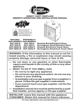
Figure 1 - Direct Vent Fireplace
Outer
Glass Door
Log Set
Flue Collar
Nailing Flange
Lower Door/
Control Cover
Herringbone Brick
Refractories
PRODUCT IDENTIFICATION
Grate
PRODUCT FEATURES
These are a few facts that can help you under-
stand and enjoy your direct vent replace:
• The venting system may be routed to the
outside of your home in several ways. It
may vent through the roof (vertical) or it
may vent to an outside/exterior wall (hori-
zontal). The vent pipe installation is very
important to allow for proper operation.
You must follow the venting instructions
very carefully for either vertical or horizontal
applications.
• This replace may be installed in any room
of your house provided all local codes and
these installation instructions are followed.
• Each time you turn on your replace, you
may notice some amount of condensation
on the inside of the replace glass. This
is normal and will disappear after 10-20
minutes of operation.
• Your direct vent gas fireplace system
(replace and venting) is a balanced and
sealed gas operating unit. It requires ap-
proximately 10-20 minutes of operating
time before the ame pattern stabilizes.

www.desatech.com
123163-01C6
Figure 2 - Common Fireplace Locations
Flush with a wall
Through exterior wall
enclosed in a chase
Corner
installation
Figure 3 - Fireplace Top Dimensions
PRE-INSTALLATION
LOCATION AND SpACE
REqUIREMENTS
Determine the safest and most efcient loca-
tion for your direct vent replace. Make sure
that rafters and wall studs are not in the way of
the venting system. Choose a location where
the heat output is not affected by drafts, air
conditioning ducts, windows or doors. Figure
2 shows some common locations. Be aware
of all restrictions and precautions before
deciding the exact location for your replace
and termination cap.
When deciding the location of your replace,
follow these rules:
• Do not connect this replace venting to a
chimney ue serving a separate solid-fuel
burning replace or appliance.
• Due to high temperatures, do not locate this
replace in high trafc areas, windy or drafty
areas or near furniture or draperies.
• Proper clearances must be maintained.
• If your replace is to be installed directly on
carpeting, vinyl tile or any combustible mate-
rial other than wood, it must be installed on a
metal or wood panel extending the full width
and depth of the replace (see Figure 3).
• Your replace is designed to be used in
zero clearance installations. Wall or fram-
ing material can be placed directly against
any exterior surface on back, sides or top
of your replace, except where standoff
spacers are integrally attached. If standoff
spacers are attached to your replace,
these spacers can be placed directly
against wall or framing material. See fram-
ing details, page 7.
• When locating termination cap, it is impor-
tant to observe the minimum clearances
shown in Figure 7, page 8.
• If recessing into a wall, you can avoid extra
framing by positioning your replace against
an already existing framing member.
• Do not recess termination cap into a wall
or siding.
• You may paint the termination cap with
450º F (232º C) heat-resistant paint to
coordinate with the exterior nish.
• There must not be any obstruction such as
bushes, garden sheds, fences, decks or
utility buildings within 24" from the front of
the termination cap and the front of outside
air vent.
• Do not locate termination cap and outside
air vent where excessive snow or ice build
up may occur. Be sure to clear vent ter-
mination area after snow falls to prevent
accidental blockage of venting system.
When using snow blowers, do not direct
snow towards vent termination area.
29" (36")
34
3
/
4
" (42")
21" (36")
25" (42")
41
1
/
4
" (36")
48
1
/
4
" (42")
11
7
/
8
" (36")
13
5
/
8
" (42")

www.desatech.com
123163-01C 7
C
B
A
D
E
F
G
3
2
1
4
5
6
7
Wall
CLEARANCES
Minimum clearances to combustibles for the
replace are as follows:
*Back and sides 1"
Perpendicular walls 6"
Floor 0"
Ceiling to louver opening 42"
Front 36"
Top of Standoffs 0"
Vent (See venting instructions
for specic venting
clearances.)
Combustible material with a maximum thick-
ness of 5/8" may be ush with the top front
of replace.
* For back and sides of replace, do not pack
with insulation or other materials. 1" clearance
not required at nailing anges.
NOTICE: This replace is intend-
ed for use as supplemental heat.
Use this replace along with
your primary heating system.
Do not install this replace as
your primary heat source. If you
have a central heating system,
you may run system’s circulat-
ing blower while using replace.
This will help circulate the heat
throughout the house.
FRAMING AND FINISHING
Figure 4 shows typical framing of this replace.
Figure 5 shows framing for corner installation.
All minimum clearances must be met.
If you are using a separate combustible man-
tel piece, refer to Figure 6 for proper instal-
lation height. You can install noncombustible
mantels at any height above the replace.
Note: Noncombustible mantels may discolor!
PRE-INSTALLATION
Continued
43
1
/
4
"
(36")
47
1
/
4
"
(42")
41
1
/
2
"
(36")
48
1
/
2
"
(42")
Figure 4 - Framing Clearances with
Outside Air Flex Duct
Figure 5 - Framing Clearances for Corner
Installation
Figure 6 - Clearances for Combustible
Mantels
Ref.
Mantel
Depth Ref.
Mantel from
Top of Opening
1 14" A 16"
2 12" B 14"
3 10" C 12"
4 8" D 10"
5 6" E 8"
6 4" F 6"
7 2" G 4"
36
3
/
8
"
(36")
43
3
/
8
" (42")
43" (36"), 50" (42")
42" (36"), 49" (42")
15
3
/
4
"
(36")
19" (42")
51
3
/
8
"
(36")
61
3
/
4
" (42")
Nailing
Tabs

www.desatech.com
123163-01C8
Fixed
Closed
Openable
Fixed
Closed
V
V
V
V
V
V
V
V
X
X
V
X
G
G
J
F
B
B
K
N
H
I
A
N
E
L
D
B
M
A
C
B
V
V
A
G
G
B
TERMINATION CAP
AIR SUPPLY INLET
GAS METERRESTRICTED AREA
(TERMINATION PROHIBITED)
A = clearance above grade, veranda, porch, deck, or
balcony [*12" (30.5 cm) minimum]
B = clearance to window or door that may be opened
[6" (15 cm) min. for 10,000 Btu or less; 9" (23 cm) in US
if between 10,000 and 50,000, 12" (30 cm) in Canada
if between 10,000 and 100,000; 12" (30 cm) in US if
greater than 50,000, 36" (91 cm) in Canada if greater
than 100,000]
C = clearance to permanently closed window
[minimum 12" (30.5 cm) recommended to prevent
condensation on window]
D = vertical clearance to ventilated soffit located above the
terminal within a horizontal distance of 24" (61 cm) from
the center-line of the terminal [18" (45.7 cm) minimum]
E = clearance to unventilated soffit [12" (30.5 cm) minimum]
F = clearance to outside corner (see below)
G = clearance to inside corner (see below)
H = *not to be installed above a meter/regulator assembly
within 36" (91.4 cm) horizontally from the center line
of the regulator
I = clearance to service regulator vent outlet [*72" (182.9 cm)
minimum]
J = clearance to non-mechanical air supply inlet to building
or the combustion air inlet to any other fireplace
[6" (15 cm) min. for 10,000 Btu or less; 9" (23 cm) in US
if between 10,000 and 50,000, 12" (30 cm) in Canada
if between 10,000 and 100,000; 12" (30 cm) in US if
greater than 50,000, 36" (91 cm) in Canada if greater
than 100,000]
K = clearance to a mechanical air supply inlet [*In Canada,
6 ft. (1.83m) minimum; In US 3 ft. (91 cm) above if within
10 ft. (3 m) horizontally]
L = † clearance above paved side-walk or a paved driveway
located on public property [*84" (213.3 cm) minimum]
M = clearance under veranda, porch, deck
[*12" (30.5 cm) minimum ‡]
N = clearance above a roof shall extend a minimum of
24" (61 cm) above the highest point when it passes
through the roof surface and any other obstruction within
a horizontal distance of 18" (45.7 cm)
† vent shall not terminate directly above a side-walk or paved driveway which is located between two
single family dwellings and serves both dwellings*
‡ only permitted if veranda, porch, deck or balconey is fully open on a minimum of 2 sides beneath the floor*
* as specified in CAN/CSA B149 (.1 or .2) Installation Codes (1991) for Canada and U.S.A.
Note: Local codes or regulations may require different clearances
A = 6" (15.2 cm)
Inside Corner
V
B
E
V
B = 6" (15.2 cm)
C = Maximum depth of 48" (121.9 cm)
for recessed location
D = Minimum width for back wall of
recessed location -
Combustible - 38" (965 mm)
Noncombustible - 24" (61 cm)
E = Clearance from corner in
recessed location-
Combustible - 6" (15.2 cm)
Noncombustible - 2" (5.1 cm)
Outside Corner Recessed Location
G
H
G = 12" (30.5 cm) minimum clearance
Balcony with No Side Wall
V
J
Combustible &
Noncombustible
H = 24" (61 cm)
J = 20" (50.8 cm)
Balcony with Perpendicular Side Wall
C
D
C
Termination Clearances for Buildings with Combustible and Noncombustible Exteriors
Openable
Figure 7 - Minimum Clearances for Termination Cap
LOCATION OF TERMINATION CAP

www.desatech.com
123163-01C 9
REQUIREMENTS FOR THE COMMONWEALTH OF
MASSACHUSETTS
For all side wall horizontally vented gas fueled
equipment installed in every dwelling, building or
structure used in whole or in part for residential
purposes, including those owned or operated by
the Commonwealth and where the side wall ex-
haust vent termination is less than seven (7) feet
above nished grade in the area of the venting,
including but not limited to decks and porches,
the following requirements shall be satised:
INSTALLATION OF CARBON
MONOXIDE DETECTORS
At the time of installation of the side wall horizon-
tal vented gas fueled equipment, the installing
plumber or gastter shall observe that a hard
wired carbon monoxide detector with an alarm
and battery backup is installed on the oor level
where the gas equipment is to be installed. In
addition, the installing plumber or gastter shall
observe that a battery operated or hard wired car-
bon monoxide detector with an alarm is installed
on each additional level of the dwelling, building or
structure served by the side wall horizontal vented
gas fueled equipment. It shall be the responsibility
of the property owner to secure the services of
qualied licensed professionals for the installation
of hard wired carbon monoxide detectors.
In the event that the side wall horizontally
vented gas fueled equipment is installed
in a crawl space or an attic, the hard wired
carbon monoxide detector with alarm and
battery back-up may be installed on the next
adjacent oor level.
In the event that the requirements of this
subdivision can not be met at the time of
completion of installation, the owner shall
have a period of thirty (30) days to comply with
the above requirements; provided, however,
that during said thirty (30) day period, a battery
operated carbon monoxide detector with an
alarm shall be installed.
Approved Carbon Monoxide Detectors
Each carbon monoxide detector as required
in accordance with the above provisions shall
comply with NFPA 720 and be ANSI/UL 2034
listed and IAS certied.
SIGNAGE
A metal or plastic identication plate shall be
permanently mounted to the exterior of the
building at a minimum height of eight (8) feet
above grade directly in line with the exhaust
vent terminal for the horizontally vented gas
fueled heating appliance or equipment. The
sign shall read, in print size no less than 1/2" in
size, "GAS VENT DIRECTLY BELOW. KEEP
CLEAR OF ALL OBSTRUCTIONS".
INSpECTION
The state or local gas inspector of the side
wall horizontally vented gas fueled equipment
shall not approve the installation unless, upon
inspection, the inspector observes carbon
monoxide detectors and signage installed in
accordance with the provisions of 248 CMR
5.08(2)(a) 1 through 4.
EXEMPTIONS: The following equipment is ex-
empt from 248 CMR 5.08(2)(a) 1 through 4:
• The equipment listed in Chapter 10 entitled
"Equipment Not Required To Be Vented"
in the most current edition of NFPA 54 as
adopted by the Board; and
• Product Approved side wall horizontally
vented gas fueled equipment installed in a
room or structure separate from the dwell-
ing, building or structure used in whole or
in part for residential purposes.
MANUFACTURER REqUIREMENTS
Gas Equipment Venting System Provided
When the manufacturer of Product Approved
side wall horizontally vented gas equipment
provides a venting system design or venting
system components with the equipment, the
instructions provided by the manufacturer for
installation of the equipment and the venting
system shall include:
• Detailed instructions for the installation of
the venting system design or the venting
system components; and
• A complete parts list for the venting system
design or venting system.
Gas Equipment Venting System Not
provided
When the manufacturer of a Product Ap-
proved side wall horizontally vented gas fu-
eled equipment does not provide the parts for
venting the ue gases, but identies "special
venting systems", the following requirements
shall be satised by the manufacturer:
•
The referenced "special venting system" in-
structions shall be included with the appliance
or equipment installation instructions; and
• The "special venting systems" shall be Prod-
uct Approved by the Board, and the instruc-
tions for that system shall include a parts list
and detailed installation instructions.
A copy of all installation instructions for all
Product Approved side wall horizontally
vented gas fueled equipment, all venting in-
structions, all parts lists for venting instruc-
tions, and/or all venting design instructions
shall remain with the appliance or equipment
at the completion of the installation.

www.desatech.com
123163-01C10
VENTING INSTALLATION
NOTICE: Do not seal termination
cap to vent pipe. Cap must be
removable for vent inspection
and maintenance.
INSTALLATION pRECAUTIONS
• Wear gloves and safety glasses for
protection
• Use extreme caution when using ladders
or when on roof tops
• Be aware of electrical wiring locations in
walls and ceilings
The following actions will void the warranty
on your venting system:
• Installation of any damaged venting
component
• Unauthorized modication of the venting sys-
tem (Do not cut or alter vent components)
• Installation of any component part not
manufactured or approved by DESA
Heating, LLC
• Installation other than as instructed by
these instructions
WARNING: This gas replace
and vent assembly must be
vented directly to the outside.
The venting system must NEVER
be attached to a chimney serv-
ing a separate solid fuel burning
appliance. Each direct vent gas
appliance must use a separate
vent system. Do not use com-
mon vent systems.
WARNING: Vent pipe air
space clearances to combus-
tibles are 1" on all sides except
on the horizontal sections,
which require 2" clearances
from the top of the pipe. Where
the termination cap penetrates
a combustible wall, 1" air space
clearance is required.
NOTICE: Read these instruc-
tions completely before attempt-
ing installation.
These models are tested and approved for
use with DESA Heating, LLC (direct vent) pipe
components and terminations.
The venting system must terminate on the
outside of the structure and can not be at-
tached to a chimney or ue system serving a
separate solid fuel or gas burning appliance.
A direct vent appliance must have its own
venting system. DO NOT common vent this
appliance.
These models are approved to be vented
either horizontally through an outside wall or
vertically through a roof or chase enclosure
using the following guidelines:
• When venting system terminates horizon-
tally on an outside wall, you may install
a standoff if the termination cap is to be
installed directly on a combustible nish
such as vinyl, wood, stucco, etc.
• Never run the vent downward as this may
cause excessive temperatures which could
cause a re.
• Vent pipe air space clearances to com-
bustibles are 1" on all sides except on the
horizontal sections, which requires 2" clear-
ance from the top of the pipe. Where the
termination cap penetrates a combustible
wall, 1" air space clearance is required.
• Have replace and selected vent compo-
nents on hand to help determine the exact
measurements when elbowing or offsetting.
Always use wall restops when penetrating
walls and restops when penetrating ceil-
ings or attic spaces.
• For installation of replace at elevations of
4000 feet or greater, pay special attention
to venting requirement recommendations.
WARNING: Read all instruc-
tions completely and thoroughly
before attempting installation.
Failure to do so could result in
serious injury, property damage
or loss of life.
NOTICE: Failure to follow these in-
structions will void the warranty.

www.desatech.com
123163-01C 11
INSTALLATION pLANNING
There are two basic types of direct vent
installation:
• Horizontal Termination
• Vertical Termination
Horizontal Termination Installation
IMPORTANT: Horizontal square terminations
require only inner portion of wall restop. Hori-
zontal installations using round termination
require exterior portion of wall restop.
1. Set replace in its desired location and de-
termine the route your horizontal venting
will take. Do not secure replace until all
venting has been installed. Some instal-
lations require sliding replace in and out
of position to make nal venting connec-
tions. Figures 14 and 15 on page 12 show
different congurations for venting with
horizontal termination that will help you
decide which application best suits your
installation. Check to see if wall studs or
roof rafters are in the path of your desired
venting route. If they are, you may want
to adjust location of replace.
2. Direct vent pipe sections and components
are designed with special twist-lock con-
nections.
Twist-Lock procedure: Female ends of
pipes have locking lugs (indentations).
These lugs will slide straight into match-
ing slots on male ends of adjacent pipes.
Push pipe sections together and twist
one section clockwise approximately one-
quarter turn until sections are fully locked
(see Figure 8).
Note: Horizontal runs of vent must be sup-
ported every three feet. Use wall straps
for this purpose.
3. Assemble desired combination of pipe
and elbows to replace ue collar. If there
are long portions of venting run, pre-as-
sembled pipe sections may be installed
as subassemblies for convenience.
4. Carefully determine location where vent
pipe assembly will penetrate outside wall.
Center of hole should line up with center
line of horizontal vent pipe. Mark wall for
an 11
1
/
2
" x 11
1
/
2
" square hole. Cut and
frame square hole in exterior wall where
vent will be terminated. If wall being pen-
VENTING INSTALLATION
Continued
Figure 8 - Vent Pipe Connections
Female
Locking Lugs
Male
Slots
Figure 9 - Vent Opening Requirements
Center
of Hole
etrated is constructed of noncombustible
material, such as masonry block or con-
crete, a 8
1
/
2
" hole with zero clearance is
acceptable (see Figure 9).
WARNING: Do not recess
vent termination into any wall.
This will cause a re hazard.
(Framing
Detail)
11
1
/
2
"
11
1
/
2
" Inside Framing
11
1
/
2
"
8
1
/
2
"
Vent
O
pening
Combustible Wall
Vent Opening
Noncombustible Wall

www.desatech.com
123163-01C12
VENTING INSTALLATION
Continued
5. Noncombustible Exterior Wall: Position
horizontal vent cap in center of the 8
1
/
2
"
round hole and attach to exterior wall
with four wood screws provided. Before
attaching vent cap to exterior wall, run a
bead of non-hardening mastic (pliable
sealant) around outside edges to make a
seal between it and outside wall.
Note: Four wood screws provided should
be replaced with appropriate fasteners for
stucco, brick, concrete or other types of
sidings (see Figure 10).
Combustible Exterior Wall: For vinyl
siding, stucco or wood exteriors, a siding
standoff may be installed between vent
cap and exterior wall. Siding standoff
prevents excessive heat from damaging
siding materials. Siding material must be
cut to accommodate standoff. Bolt vent
cap to standoff. Apply non-hardening
mastic around outside edge of standoff.
Position standoff/cap assembly in the
center of 11
1
/
2
" square hole and attach to
exterior wall with provided wood screws
(see Figure 11). Siding standoff must sit
ush against exterior fascia material.
6. Connecting Vent Cap with Horizontal
Vent Pipe: Slide wall restop over vent
pipe before connecting horizontal run to
vent cap (see Figure 12).
Figure 10 - Installing Horizontal Vent Cap
(Noncombustible Exterior)
Wood
Screw
Vent Cap
Figure 11 - Installing Siding Standoff
(Combustible Exterior Wall)
Cut Siding Away to
Fit Standoff
Wood
Screw
Screws
Standoff
Vent
Cap
Apply Mastic
to All Four Sides
Vent Cap
(Horizontal
Termination)
Interior Wall
Surface
Wall
Firestop
Horizontal
Vent Pipe
Figure 12 - Connecting Vent Cap with
Horizontal Vent Pipe
Screw
Apply
Mastic to All
Four Sides
Carefully move replace, with vent as-
sembly attached, toward wall and insert
vent pipe into horizontal termination. Pipe
overlap should be a minimum of 1
1
/
4
" (see
Figure 13, page 13).
Slide wall restop against interior wall
surface and attach with screws provided.
See Figure 13, page 13, for horizontal
termination details.
Place replace into position and shim with
noncombustible material if needed. Nail or
screw side anges to framing to secure
unit in place. IMPORTANT: Make sure re-
place is level before securing. If replace
is not level it will not work properly.

www.desatech.com
123163-01C 13
VENTING INSTALLATION
Continued
Figure 13 - Typical Horizontal
Termination Cap Mounting with
Additional Siding Standoff Installed
Siding
Standoff
Screws
High Wind
Termination
Apply
Mastic to
Outside
Edge of
Standoff
Exterior Wall with Vinyl Siding
11
1
/
2
" x 11
1
/
2
"
Framed Opening
Maintain 1"
Minimum Air
Space Around
Outer Pipe When
Penetrating a Wall
Minimum
Pipe
Overlap
1
1
/
4
Wall
Firestop
Direct
Vent
Pipe
Horizontal Termination Congurations
Figure 14 shows a conguration for venting
with horizontal termination with a chart of
critical minimum and maximum dimensions
which MUST be met.
NOTICE: Do not seal termination
cap to vent pipe. Cap must be
removable for vent inspection
and maintenance.
WARNING: Never run vent
downward as this may cause
excessive temperatures which
could cause a re. Operation of
improperly installed and main-
tained venting system could
result in serious injury, property
damage or loss of life.
GROUND FLOOR INSTALLATION
Recommended Applications:
• Through the wall using round or square
termination
• NOT FOR CORNER INSTALLATION
Figure 14 - Horizontal Termination Using
One 90° Elbow
Vertical Termination Installation
Note: Vertical restrictor must be installed in
all vertical installations.
1. Determine route your vertical venting will
take. If ceiling joists, roof rafters or other
framing will obstruct venting system, con-
sider an offset (see Figure 15, page 14)
to avoid cutting load bearing members.
Note: Pay special attention to these instal-
lation instructions for required clearances
(air space) to combustibles when passing
through ceilings, walls, roofs, enclosures,
attic rafters, etc. Do not pack air spaces
with insulation. Also note maximum
vertical rise of venting system and any
maximum horizontal offset limitations.
Wall
Firestop
H
90° Elbow
V + 90· Elbow
Horizontal High
Wind Square
Termination
64" Min. (42")
61" Min. (36")
1' Pipe Min On
Horizontal Run
(V) Vertical
Minimum
Required
Vertical Pipe
(H) Horizontal
Maximum
21" 1 ft. 3 ft.
33" 2 ft. 7 ft.
45" 3 ft. 11 ft.
57" 4 ft. 20 ft.
V + H = 40 feet maximum
H = 20 feet maximum

www.desatech.com
123163-01C14
Flat Ceiling Installation
1. Cut a 11
1
/
2
" square hole in ceiling using
locating hole as a center point. Opening
should be framed to 11
1
/
2
" x 11
1
/
2
" inside
dimensions, as shown in Figure 8 on page
9 using framing lumber the same size as
ceiling joists. If area above ceiling is an
insulated ceiling or an attic, nail restop
from top side. This prevents loose insula-
tion from falling into required clearance
space. If area above ceiling is a living
space, install restop below framed hole.
Firestop should be installed with no less
than three nails per side (see Figure 15).
VENTING INSTALLATION
Continued
Figure 15 - Offset with Wall Strap and 45°
Elbows
45° Elbow
Wall Strap
Roof Flashing
Ceiling Firestop
2. Assemble desired lengths of pipe and
elbows necessary to reach from replace
ue up through restop. Be sure all pipe
and elbow connections are fully twist-
locked (see Figure 8, page 11).
3. Cut a hole in the roof using locating hole
as a center point. (Cover any exposed
open vent pipes before cutting hole in
roof.) The 11
1
/
2
" x 11
1
/
2
" hole must be
measured on the horizontal; actual length
may be larger depending on pitch of roof.
There must be a 1" clearance from vent
pipe to combustible materials. Frame
opening as shown in Figure 9, page 11.
4. Connect a section of pipe and extend up
through hole.
Note: If an offset is needed to avoid
obstructions, you must support vent pipe
every 3 feet. Use wall straps for this pur-
pose (see Figure 15). Whenever possible,
use 45° elbows instead of 90° elbows. The
45° elbow offers less restriction to the ow
of ue gases.
5. Place ashing over pipe section(s) ex-
tending through roof. Secure base of
ashing to roof and framing with roong
nails. Be sure roong material overlaps
top edge of ashing as shown in Figure
15. There must be a 1" clearance from
vent pipe to combustible materials.
6. Continue to add pipe sections until height
of vent cap meets the minimum building
code requirements described in Figure 7
on page 8.
Note: You must increase vent height for
steep roof pitches. Nearby trees, adjoining
rooines, steep pitched roofs and other
similar factors may cause poor draft or
down-drafting in high winds. Increasing
vent height may solve this problem.
7. Twist-lock vent cap onto last section of
vent pipe.
2. Set replace in desired location. Drop a
plumb line down from ceiling to position
of replace exit ue. Mark center point
where vent will penetrate ceiling. Drill a
small locating hole at this point.
3. Drop a plumb line from inside of roof to
locating hole in ceiling. Mark center point
where vent will penetrate roof. Drill a small
locating hole at this point.

www.desatech.com
123163-01C 15
Figure 16 - Installing Firestop
If area above is a living space, install
restop below framed hole.
If area above is an attic or insulated area,
install restop above framed hole.
Note: If vent pipe passes through any occupied ar-
eas above rst oor, including storage spaces and
closets, you must enclose pipe. You may frame
and sheetrock enclosure with standard construc-
tion material. Make sure and meet the minimum
allowable clearances to combustibles. Do not ll
any required air spaces with insulation.
Vertical Termination Congurations
Figure 17 shows the congurations for vertical
termination.
VENTING INSTALLATION
Continued
Figure 17 - Vertical Venting Conguration
HIGH ALTITUDE INSTALLATION
Your DESA Heating, LLC direct vent replace
has been tested and approved for elevations
from 0-2000 feet.
Fireplaces for high altitude (DVF-36AN(H,S)-S
and DVF-42AN(H,S)-S) are for installations
above 4,000 feet only. These fireplaces are
equipped with parts specic for higher altitudes.
When installing a non-high altitude replace at
an elevation above 2000 feet, you may need
to decrease the input rating by changing the
existing burner orice to a smaller size. Reduce
input 4% for each 1000 feet above sea level.
Check with your local gas company for proper
orice size identication.
When installing this replace at an elevation
above 4500 feet, check with local authorities.
PARTS LIST FOR VENTING KITS
AND COMpONENTS
DESA (5/8") Pipe & Vent Kits
Number Description
P58-6 6" Section Double Wall Pipe,
Galvanized
P58-12 12" Section Double Wall Pipe,
Galvanized
P58-24 24" Section Double Wall Pipe,
Galvanized
P58-36 36" Section Double Wall Pipe,
Galvanized
P58-48 48" Section Double Wall Pipe,
Galvanized
PA58-712 Adjustable 7"-12" Section Double
Wall Pipe, Galvanized
E58-45 45° Elbow, Galvanized
E58-90 90° Elbow, Galvanized
HTS-58 Horizontal Square Termination,
Galvanized
VT-58 Vertical Round Termination,
Galvanized
SC-58 Storm Collar, Galvanized
WF-58 Wall Firestop, Galvanized
RF-58-6 Roof Flashing - 0 to 6/12 Pitch,
Galvanized
RF-58-12 Roof Flashing - 6/12 to 12/12 Pitch,
Galvanized
VR-58 Vertical Restrictor, Galvanized
S-58 Vinyl Siding Standoff, Galvanized
WS-58 Wall Strap
CS-58 Cathedral Ceiling Support
FP-58 Firestop Plate
SF-58 Stucco Flashing - For use with
HTS-58
RF-58 Flat Roof Flashing
Vertical
Venting
V = 40' max.

www.desatech.com
123163-01C16
FIREPLACE INSTALLATION
CHECK GAS TYPE
Use proper gas type for the replace unit you
are installing. If you have conicting gas types,
do not install replace. See retailer where you
purchased the replace for proper replace
according to your gas type.
INSTALLING GAS pIpING TO
FIREpLACE LOCATION
WARNING: A qualified
service person must connect
replace to gas supply. Follow
all local codes.
CAUTION: For propane/LP
units, never connect replace di-
rectly to the propane/LP supply.
This heater requires an external
regulator (not supplied). Install
the external regulator between
the replace and propane/LP
supply.
WARNING: For natural
gas, never connect replace to
private (non-utility) gas wells.
This gas is commonly known
as wellhead gas.
Installation Items Needed
Before installing replace, make sure you
have the items listed below.
• external regulator (supplied by installer)
• piping (check local codes)
• sealant (resistant to propane/LP gas)
• equipment shutoff valve *
• test gauge connection *
• sediment trap
• tee joint
• pipe wrench
• approved exible gas line with gas connec-
tor (if allowed by local codes)
* A CSA design-certied equipment shutoff
valve with 1/8" NPT tap is an acceptable al-
ternative to test gauge connection. Purchase
the CSA design-certied equipment shutoff
valve from your retailer.
For propane/LP connection only, the installer
must supply an external regulator. The exter-
nal regulator will reduce incoming gas pres-
sure. You must reduce incoming gas pressure
to between 11" and 14" of w.c. pressure. If
you do not reduce incoming gas pressure,
replace regulator damage could occur. Install
external regulator with the vent pointing down
as shown in Figure 18. Pointing the vent down
protects it from freezing rain or sleet.
CAUTION: Use only new,
black iron or steel pipe. Inter-
nally-tinned copper tubing may
be used in certain areas. Check
your local codes. Use pipe of
1/2" diameter or greater to allow
proper gas volume to replace.
If pipe is too small, undue loss
of volume will occur.
Installation must include an equipment shutoff
valve, union and plugged 1/8" NPT tap. Locate
NPT tap within reach for test gauge hook up.
NPT tap must be upstream from replace (see
Figure 19, page 17).
IMPORTANT: Install main gas valve (equip-
ment shutoff valve) in an accessible location.
The main gas valve is for turning on or shutting
off the gas to the appliance.
Figure 18 - External Regulator with Vent
Pointing Down (Propane/LP Only)
Propane/LP
Supply Tank
External Regulator
with Vent Pointing
Down

www.desatech.com
123163-01C 17
Check your building codes for any special
requirements for locating equipment shutoff
valve to replaces.
Apply pipe joint sealant lightly to male NPT
threads. This will prevent excess sealant from
going into pipe. Excess sealant in pipe could
result in clogged replace valves.
FIREPLACE INSTALLATION
Continued
Figure 19 - Gas Connection
CSA Design-Certied
Equipment Shutoff Valve
with 1/8" NPT Tap*
3" Minimum
Approved
Flexible
Gas Line
Cap Pipe Tee
Joint Nipple
Sediment Trap/
Drip Leg
Natural - From
Gas Meter (5.5"
W.C. to 10.5" W.C.
Pressure)
Propane/LP From
External Regulator
(11" W.C. to 14"
W.C. Pressure)
* The CSA design-certied equipment shutoff
valve may be supplied with the appliance or
you can purchase it from your retailer.
Figure 20 - Connecting Incoming Gas Line to Flex Gas Line
Red Surface Indicates For
Propane/LP Use Only
Pilot Adjustment
Inlet Pressure Tap
Outlet Pressure Tap
WARNING: Use pipe joint
sealant that is resistant to liquid
petroleum (LP) gas.
We recommend that you install a sediment
trap/drip leg in supply line as shown in Figure
19. Locate sediment trap/drip leg where it is
within reach for cleaning. Install in piping sys-
tem between fuel supply and replace. Locate
sediment trap/drip leg where trapped matter
is not likely to freeze. A sediment trap traps
moisture and contaminants. This keeps them
from going into replace gas controls. If sedi-
ment trap/drip leg is not installed or is installed
wrong, replace may not run properly.
CONNECTING FIREpLACE TO GAS
SUppLY
Installation Items Needed
• 5/16" hex socket wrench or nut-driver
• sealant (resistant to propane/LP gas, not
provided)
1. Route exible gas line (provided by in-
staller) from equipment shutoff valve to
replace. Route exible gas supply line
through one of the access holes on side
of replace.
2. Attach exible gas line from gas supply to
control valve (see Figure 20).
3. Check all gas connections for leaks. See
Checking Gas Connections, page 18.
IN
PILOT
IN
OUT
VENT
TH
TP
TH
TP
Gas Shutoff
Valve
Flexible
Gas Line
Do NOT
Kink
1/2" NPT
Incoming
Gas Line
Note:
1) Wire connections not
shown for clarity
2) * 1/8" NPT Plugged
Tapping

www.desatech.com
123163-01C18
FIREPLACE INSTALLATION
Continued
CHECKING GAS CONNECTIONS
WARNING: Test all gas piping
and connections, internal and
external to unit, for leaks after
installing or servicing. Correct
all leaks at once.
WARNING: Never use an
open ame to check for a leak.
Apply noncorrosive leak detec-
tion uid to all joints. Bubbles
forming show a leak. Correct all
leaks at once.
pRESSURE TESTING GAS SUppLY
pIpING SYSTEM
Test Pressures In Excess Of 1/2 PSIG
(3.5 kPa)
1. Disconnect replace and its individual
equipment shutoff valve from gas supply
piping system. Pressures in excess of 1/2
psig (3.5 kPa) will damage replace gas
regulator.
2. Cap off open end of gas pipe where equip-
ment shutoff valve was connected.
3. Pressurize supply piping system by either
opening propane/LP supply tank valve
for propane/LP gas replace or opening
main gas valve located on or near gas
meter for natural gas replace or using
compressed air.
4. Check all joints of gas supply piping sys-
tem. Apply noncorrosive leak detection
uid to all joints. Bubbles forming show a
leak. Correct all leaks at once.
5. Reconnect fireplace and equipment
shutoff valve to gas supply. Check recon-
nected ttings for leaks.
Test Pressures Equal To or Less Than
1/2 PSIG (3.5 kPa)
1. Close equipment shutoff valve (see Fig-
ure 21).
2. Pressurize supply piping system by either
opening propane/LP supply tank valve
for propane/LP gas replace or opening
main gas valve located on or near gas
meter for natural gas replace or using
compressed air.
Figure 21 - Equipment Shutoff Valve
Open
Closed
Equipment
Shutoff Valve
3. Check all joints from propane/LP supply
tank or gas meter to equipment shutoff
valve (see Figure 22 or Figure 23). Apply
noncorrosive leak detection uid to all
joints. Bubbles forming show a leak.
4. Correct all leaks at once.
Figure 22 - Checking Gas Joints for
Propane/LP Gas Fireplace
Propane/LP
Supply Tank
Gas Valve
Equipment
Shutoff Valve
pRESSURE TESTING FIREpLACE GAS
CONNECTIONS
1. Open equipment shutoff valve (see Fig-
ure 21).
2. Open propane/LP supply tank valve for
propane/LP replace or main gas valve
located on or near gas meter for natural
gas replace.
Gas Meter
Gas Valve
Equipment
Shutoff Valve
Figure 23 - Checking Gas Joints for
Natural Gas Fireplace

www.desatech.com
123163-01C 19
FIREPLACE INSTALLATION
Continued
3. Make sure control knob of replace is in
the OFF position.
4. Check all joints from equipment shutoff
valve to gas valve (see Figure 22 or
Figure 23, page 18). Apply noncorrosive
leak detection uid to all joints. Bubbles
forming show a leak. Correct all leaks at
once.
5. Light replace (see Operation, page 22).
Check all other internal joints for leaks.
6. Turn off replace (see To Turn Off Gas to
Appliance, page 23).
REMOVING/REPLACING GLASS
DOOR
CAUTION: Do not operate
this replace with a broken glass
door panel or without the glass
door panel securely in place.
For replacement part informa-
tion see Replacement Parts,
page 35.
CAUTION: Wear gloves and
safety glasses while handling
or removing broken glass.
Do not remove if glass is hot.
Keep children and pets away
from glass.
WARNING: If replace has
been running, turn off replace.
Let cool before removing glass
doors.
Figure 24 - Removing/Replacing Door
Removing Glass Door
If replacement of glass is necessary, the entire
frame assembly must be replaced. Gloves
must be worn when removing/replacing glass
door. If glass is broken tape remaining glass
onto frame before removing.
1. Remove screens if installed.
2. Open bottom access panel.
3. Unlock 2 door latches on bottom of
rebox.
4. Tilt open glass door 45° from the bottom
of rebox and lift up to release door from
rebox top retainer (see Figure 24).
Replacing Glass Door
1. Position door frame in front of rebox
opening with bottom of door tilted away
from rebox (see Figure 24).
2. Hook top ange of door frame over top of
rebox frame.
3. Secure 2 bottom door latches.
Door
Retainer
Glass
Door
Bottom
Access Panel
Door
Latches

www.desatech.com
123163-01C20
FIREPLACE INSTALLATION
Continued
LAVA ROCK, DECORATIVE GRATE,
EMBER FLAKES AND SCRAP LOG
INSTALLATION
Lava rock, ember akes and scrap log pieces are
included with your replace. Install these items
while glass doors are open and/or removed.
1. Follow instructions from Removing/Re-
placing Glass Door, page 19, to move
glass out of the way of this installation.
2. For 36" models only, install 3 loose logs
by placing log #1, log #2 and log #3 onto
one piece log as shown in Figure 25.
3. Place lava rock around base of burner.
Make sure burner ports are not covered
(see Figure 26).
4. Place ember akes around front and sides of
burner and on burner ports (see Figure 27).
This will create the glowing ember appearance
as the ame touches the ember akes. Do not
block burner ports or pilot ports by overlapping
ember akes in one area. It is not necessary
to use all ember material provided.
5. Place scrap log pieces randomly behind
grate as shown in Figure 28 on lava rock
and around (but not on) burner ports.
6. Place grate in front of logs as shown in
Figure 28. Be sure grate is balanced so it
does not fall or lean onto logs. Grate does
not attach to hearth assembly.
Figure 26 - Installing Lava Rock
Figure 27 - Installing Ember Flakes
Figure 28 - Installing Scrap Log Pieces
Lava Rock
Ember Flakes
Scrap Log Pieces
REMOVING LOGSET/BURNER
MODULE
Connecting and Disconnecting Gas Line
WARNING: A qualied ser-
vice person must connect and
disconnect replace with gas
supply. Follow all local codes.
1. Using a 5/16" hex socket wrench or nut-
driver, connect or disconnect exible gas line
and control valve (see Figure 29, page 21).
2. After connecting gas line to control valve,
always test for leaks.
Figure 25 - Installing Loose Logs
Log #2
Log #1
Log #3
/