Page is loading ...

GR64 GSM/GPRS Modem
Integrators Manual

LZT 123 1834 2
The information contained in this document is the proprietary information of Sony Ericsson
Mobile Communications International. The contents are confidential and any disclosure to
persons other than the officers, employees, agents or subcontractors of the owner or
licensee of this document, without the prior written consent of Sony Ericsson Mobile
Communications International, is strictly prohibited.
Further, no portion of this publication may be reproduced, stored in a retrieval system, or
transmitted in any form or by any means, electronic or mechanical, including photocopying
and recording, without the prior written consent of Sony Ericsson Mobile Communications
International, the copyright holder.
First Edition (March 2006)
Sony Ericsson Mobile Communications International publishes this manual without making
any warranty as to the content contained herein. Further Sony Ericsson Mobile
Communications International reserves the right to make modifications, additions and
deletions to this manual due to typographical errors, inaccurate information, or
improvements to programs and/or equipment at any time and without notice. Such changes
will, nevertheless be incorporated into new editions of this manual.
All rights reserved.
© Sony Ericsson Mobile Communications International, 2006
Publication number: LZT 123 1834
Printed in US

LZT 123 1834 3
Contents
Overview ...................................................................................................... 8
1 Introduction ........................................................................................... 9
1.1 TARGET USERS.......................................................................................................... 9
1.2 PREREQUISITES ......................................................................................................... 9
1.3 MANUAL STRUCTURE................................................................................................ 9
1.4 NOTATION ............................................................................................................. 10
1.5 ACKNOWLEDGEMENTS ............................................................................................ 10
2 GR64 Wireless Modem.......................................................................... 11
2.1 ABOUT THE GR64 ................................................................................................... 11
2.2 WIRELESS MODEMS IN A COMMUNICATION SYSTEM................................................. 12
2.3 FEATURES............................................................................................................... 14
2.3.1 TYPES OF MOBILE STATION .............................................................................. 14
2.3.2 SHORT MESSAGE SERVICE ................................................................................ 14
2.3.3 VOICE CALLS ................................................................................................... 15
2.3.4 DATA .............................................................................................................. 15
2.3.5 GPRS MULTI-SLOT SUPPORT............................................................................. 16
2.3.6 SIM CARD ........................................................................................................ 16
2.3.7 POWER CONSUMPTION..................................................................................... 16
2.3.8 OTHER FEATURES ............................................................................................ 17
2.4 SERVICE AND SUPPORT ........................................................................................... 18
2.4.1 WEB PAGES ...................................................................................................... 18
2.4.2 AT COMMANDS MANUAL ................................................................................. 18
2.4.3 M2MPOWER APPLICATION GUIDE ..................................................................... 18
2.4.4 DEVELOPER’S KIT ............................................................................................. 18
2.5 PRECAUTIONS......................................................................................................... 19
2.6 GUIDELINES FOR SAFE AND EFFICIENT USE .............................................................. 19
2.6.1 GENERAL USAGE .............................................................................................. 19
2.6.2 RADIO FREQUENCY (RF) EXPOSURE AND SAR .................................................... 20
2.6.3 PERSONAL MEDICAL DEVICES ........................................................................... 20
2.6.4 DISPOSAL OF OLD ELECTRONIC EQUIPMENT ..................................................... 20

LZT 123 1834 4
3 Abbreviations ....................................................................................... 22
Integrating the Wireless Modem ................................................................. 24
4 Mechanical Description......................................................................... 25
4.1 INTERFACE DESCRIPTION ........................................................................................ 25
4.2 PHYSICAL DIMENSIONS ........................................................................................... 27
5 System Connector Interface.................................................................. 29
5.1 OVERVIEW .............................................................................................................. 29
5.2 DEALING WITH UNUSED PINS................................................................................... 32
5.3 GENERAL ELECTRICAL AND LOGICAL CHARACTERISTICS.......................................... 34
5.3.1 LEVEL SHIFTER INTERFACES.............................................................................. 34
5.3.1.1 COMMON LEVEL SHIFTER INTERFACE ............................................................ 34
5.3.1.2 I2C LEVEL SHIFTER INTERFACE...................................................................... 36
5.4 GROUNDS............................................................................................................... 37
5.4.1 ANALOGUE GROUND (AREF) ............................................................................. 37
5.4.2 COMMON GROUND (GND)................................................................................ 37
5.5 REGULATED POWER SUPPLY INPUT (VCC)................................................................. 38
5.6 VOLTAGE REFERENCE (VREF) ................................................................................... 39
5.6.1 VREF AS AN OUTPUT........................................................................................ 39
5.6.2 VREF AS AN INPUT ........................................................................................... 39
5.7 BATTERY CHARGING INPUT (CHG_IN) ...................................................................... 41
5.7.1 CHARGING PROCESS ........................................................................................ 42
5.7.2 SERIES DIODE................................................................................................... 43
5.7.3 BATTERY SELECTION........................................................................................ 43
5.8 POWERING THE MODULE ON AND OFF (ON/OFF) ..................................................... 47
5.8.1 TURNING THE MODULE ON .............................................................................. 47
5.8.2 TURNING THE MODULE OFF ............................................................................. 48
5.9 ANALOGUE AUDIO .................................................................................................. 50
5.9.1 AUXILIARY AUDIO TO MOBILE STATION (AUXI).................................................. 51
5.9.2 AUXILIARY AUDIO FROM MOBILE STATION (AUXO)............................................ 52
5.9.3 MICROPHONE SIGNALS (MICIP, MICIN) .............................................................. 52
5.9.4 SPEAKER SIGNALS (EARP, EARN) ....................................................................... 53
5.10 PCM DIGITAL AUDIO (SSP) ................................................................................... 53

LZT 123 1834 5
5.10.1 PCM DATA FORMAT......................................................................................... 53
5.11 SERIAL DATA INTERFACES ................................................................................... 55
5.11.1 UART1............................................................................................................. 56
5.11.2 SERIAL DATA SIGNALS (DTM1, DFM1)............................................................... 56
5.11.2.1 SERIAL DATA FROM WIRELESS MODEM (DFM1) .............................................. 57
5.11.2.2 SERIAL DATA TO WIRELESS MODEM (DTM1) .................................................. 57
5.11.3 CONTROL SIGNALS (RTS1, CTS1, DTR1, DSR1, DCD1, RI).................................. 57
5.11.3.1 HARDWARE FLOW CONTROL RTS1 AND CTS1 ............................................... 57
5.11.3.2 REQUEST TO SEND (RTS1)............................................................................. 57
5.11.3.3 CLEAR TO SEND (CTS1) ................................................................................ 58
5.11.3.4 DATA TERMINAL READY (DTR1).................................................................... 58
5.11.3.5 DATA SET READY (DSR1) .............................................................................. 58
5.11.3.6 DATA CARRIER DETECT (DCD1) .................................................................... 58
5.11.3.7 RING INDICATOR (RI).................................................................................... 58
5.11.4 UART3 (DTM3, DFM3)...................................................................................... 59
5.11.4.1 TRANSMITTED DATA (DTM3) ........................................................................ 59
5.11.4.2 RECEIVED DATA (DFM3)................................................................................ 59
5.11.5 USB ................................................................................................................. 60
5.11.6 SIM CARD INTERFACE ...................................................................................... 61
5.11.7 SIM DETECTION (SIMDET)................................................................................. 62
5.12 SERVICE/PROGRAMMING ..................................................................................... 62
5.13 BUZZER ............................................................................................................... 63
5.14 LED..................................................................................................................... 63
5.15 GENERAL PURPOSE IO.......................................................................................... 65
5.15.1 EMBEDDED APPLICATIONS ............................................................................... 66
5.15.2 LED/IO6 CAPABILITIES ..................................................................................... 66
5.15.3 ADC4 .............................................................................................................. 66
5.16 DIGITAL TO ANALOGUE CONVERTER – DAC ......................................................... 67
5.17 ANALOGUE TO DIGITAL CONVERTERS (ADIN1, ADIN2, ADIN3, ADIN4).................. 67
5.18 I
2
C SERIAL CONTROL BUS .................................................................................... 69
5.19 BURST TRANSMISSION (TX_ON)............................................................................ 70
5.20 REAL TIME CLOCK ............................................................................................... 70
5.20.1 REAL TIME CLOCK BACKUP SUPPLY (VRTC) ....................................................... 71
5.20.2 RTC ALARM (ALARM) ....................................................................................... 72
5.20.2.1 ALARM OUTPUT FROM THE MODULE ............................................................ 72
5.20.3 ALARM UTILIZATION AS A WAKE-UP................................................................. 73
6 Antenna Connector .............................................................................. 74

LZT 123 1834 6
7 Hints for Integrating the Wireless Modem............................................. 75
7.1 SAFETY ADVICE AND PRECAUTIONS ........................................................................ 75
7.1.1 GENERAL ......................................................................................................... 75
7.2 SIM CARD ............................................................................................................... 76
7.3 ANTENNA ............................................................................................................... 76
7.4 INSTALLATION OF THE WIRELESS MODEM................................................................ 77
7.4.1 WHERE TO INSTALL THE WIRELESS MODEM....................................................... 77
7.4.1.1 ENVIRONMENTAL CONDITIONS..................................................................... 77
7.4.1.2 SIGNAL STRENGTH ....................................................................................... 77
7.4.1.3 CONNECTION OF COMPONENTS TO WIRELESS MODEM.................................. 78
7.4.1.4 NETWORK AND SUBSCRIPTION...................................................................... 78
7.4.2 HOW TO INSTALL THE WIRELESS MODEM.......................................................... 78
7.4.2.1 POWER SUPPLY ............................................................................................. 78
7.4.2.2 GROUNDS .................................................................................................... 78
7.4.2.3 AUDIO.......................................................................................................... 79
7.4.2.4 SOFTWARE UPGRADE.................................................................................... 79
7.5 ANTENNA ............................................................................................................... 79
7.5.1 GENERAL ......................................................................................................... 79
7.5.2 ANTENNA TYPE................................................................................................ 79
7.5.3 ANTENNA PLACEMENT..................................................................................... 80
7.5.4 THE ANTENNA CABLE....................................................................................... 80
7.5.5 POSSIBLE COMMUNICATION DISTURBANCES..................................................... 80
8 Embedded Applications ........................................................................ 82
8.1 FEATURES............................................................................................................... 82
8.2 IMPLEMENTATION................................................................................................... 82
8.2.1 LIMITATIONS ................................................................................................... 82
8.2.2 M2MPOWER IDE (INTEGRATED DEVELOPMENT ENVIRONMENT).......................... 83
9 TCP/IP Stack......................................................................................... 84
9.1 IMPLEMENTATION................................................................................................... 84
10 Technical Data................................................................................... 85
10.1 MECHANICAL SPECIFICATIONS............................................................................. 85
10.2 POWER SUPPLY VOLTAGE, NORMAL OPERATION................................................... 86
10.3 RADIO SPECIFICATIONS ....................................................................................... 86

LZT 123 1834 7
10.4 SIM CARD............................................................................................................ 86
10.5 ENVIRONMENTAL SPECIFICATION ........................................................................ 87
11 Regulatory Notices ............................................................................ 89
Developers Kit............................................................................................ 90
12 Introduction to the Universal Developer’s Kit ..................................... 91

LZT 123 1834 8
Overview

LZT 123 1834 9
1 Introduction
1.1 Target Users
The GR64 wireless modems are designed to be integrated into machine-to-machine
or man-to-machine communications applications.
They are intended to be used by manufacturers, system integrators, applications
developers and developers of wireless communications equipment.
1.2 Prerequisites
It is assumed that the person integrating the wireless modem into an application has
a basic understanding of the following:
• GSM networking;
• Wireless communication and antennas (aerials)
• AT commands
• ITU-T standard V.24/V.28
• Micro controllers and programming
• Electronic hardware design
1.3 Manual Structure
This manual is composed of three parts.
Part 1- Overview
This section provides a broad overview of the Gx64 family and includes a list of
abbreviations used in the manual.
Part 2 - Integrating the Wireless modem
This section describes each of the signals available on the GR64 wireless modem,
along with mechanical information. The section also provides you with design
guidelines and what is needed to commercialize an application from a regulatory
point of view.

LZT 123 1834 10
Part 3 – Developer’s Kit
This section lists the contents of the Developer’s Kit and provides the information to
setup and use the equipment.
1.4 Notation
The following symbols and admonition notation are used to draw the readers
attention to notable, or crucially-important information.
Note
Draws the readers attention to pertinent, useful or interesting
information
Tip
Provides advice, suggestions, guidance or recommendations which
augment the formal text
Caution
Cautionary information must be heeded, it draws the readers attention
to the need for understanding, care or watchfulness in relation to the
information provided
Warning
Notes marked warning must be heeded, they alert readers to
precautionary measures, risks, hazards or safety information which
directly effects equipment function, warranty or personnel safety
Danger
This information must be heeded, it identifies information and
cautionary behavior that otherwise ignored could result in catastrophic
equipment failure, bodily injury or death
1.5 Acknowledgements
Parts of this document, including text passages, tables, and illustrations, are
reproduced from copyright information by kind permission of Agere Systems Inc.
TIP
CAUTION
!
WARNING
DANGE
R
NOTE

LZT 123 1834 11
2 GR64 Wireless Modem
2.1 About the GR64
The Sony Ericsson Gx64 family of devices are Quad Band GSM/GPRS wireless modems
operating in the GSM 850/900/1800/1900 bands.
These products belong to a new generation of Sony Ericsson wireless modems, and
are intended to be used in machine-to-machine applications and man-to-machine
applications. They are used when there is a need to send and receive data (by SMS,
CSD, or GPRS), and make voice calls over the GSM network.
The GR64 conforms to the European Union (EU) Restriction of Hazardous Substances
(RoHS) directive 2002/95/EC.
The GR64 is available in four variants. Table 1: GR64 Variants lists the hardware and
software features for each variant. The device is available in two hardware variants.
Each hardware variant is available in two software variants. The first hardware variant
(/10 and /30) is equipped with PCM compatible pins but does not have a USB
interface or an integrated SIM card holder. The second hardware variant (/20 and
/40) is equipped with a USB interface and an integrated SIM card holder, but does not
have PCM compatible pins.
Table 1: GR64 Variants
Variant
PCM
Compatible
PINS
VREF Input USB
SIM Card
Holder
Embedded
Applications
DPY 102 1494/10 Yes No No No No
DPY 102 1494/20 No Yes Yes Yes No
DPY 102 1494/30 Yes No No No Yes
DPY 102 1494/40 No Yes Yes Yes Yes
One software variant is designed to be controlled from a micro-controller situated on
the host application. The other software variant offers the option to run applications
embedded onto the module itself. When using the embedded application version the
controlling script can be run internal to the module, with or without the use of an
external control.
A typical application, involves a micro-controller and a wireless modem, in which the
micro-controller sends AT commands to the wireless modem via an RS232
communications link.

LZT 123 1834 12
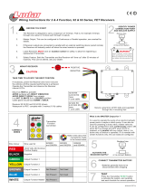
2.2 Wireless modems in a Communication System
Figure
2.2-1 and
Figure
2.2-2 illustrate the main blocks of a wireless communication
system using the wireless modem.
Figure
2.2-1 shows the communication system
when the script is embedded on the wireless modem and
Figure
2.2-2 shows the
communication system when a micro-controller is used. They also show the
communication principles of the system and the interface between the wireless
modem and the application. The definitions in the figures, as used elsewhere in this
manual, are in accordance with the recommendations of 3GPP TS 27.007.
The MS (mobile station) represents the wireless modem and SIM card. The wireless
modem excluding SIM card, is known as the ME (mobile equipment).
The DTE (data terminal equipment) is the controlling application. This can be either
an external host or an internal embedded application.
The DCE (data circuit terminating equipment) is the serial communication interface of
the MS.
SIM
SIM
GSM
ENGINE
GSM
ENGINE
DCE
DCE
DTE
DTE
SYSTEM INTERFACE
DC
POWER
STATUS &
RESPONSE
COMMAND
& CONTROL
EMBEDDED
APPLICATION
MS
GSM
NETWORK
SIM
SIM
GSM
ENGINE
GSM
ENGINE
DCE
DCE
DTE
DTE
SYSTEM INTERFACE
DC
POWER
STATUS &
RESPONSE
COMMAND
& CONTROL
EMBEDDED
APPLICATION
MS
GSM
NETWORK
Figure 2.2-1 Main Blocks in a Wireless System (embedded application)

LZT 123 1834 13
SIM
SIM
GSM
ENGINE
GSM
ENGINE
DCE
DCE
DTE
DTE
SYSTEM INTERFACE
STATUS &
RESPONSE
COMMAND
& CONTROL
MS
GSM
NETWORK
DC
POWER
GR64
SIM
SIM
GSM
ENGINE
GSM
ENGINE
DCE
DCE
DTE
DTE
SYSTEM INTERFACE
STATUS &
RESPONSE
COMMAND
& CONTROL
MS
GSM
NETWORK
DC
POWER
GR64
Figure 2.2-2 Main Blocks in a Wireless System (external micro-controller)
In accordance with the recommendations of ITU-T (International Telecommunication
Union - Telecommunications Standardization Sector) V.24, the TE communicates with
the MS over a serial interface.
The functions of the wireless modem follow the recommendations provided by 3GPP
(3rd Generation Partnership Project) and ITU-T. 3GPP is a collaboration agreement
that was established in December 1998. The collaboration agreement brings
together a number of telecommunications standards bodies which are known as
Organizational Partners
. The current Organizational Partners are ARIB, CCSA, ETSI,
ATIS, TTA, and TTC.
3GPP specifies a set of AT commands for controlling the GSM element of the wireless
modem; these commands are supplemented by Sony Ericsson specific commands.
To find out how to work with AT commands, see the AT Commands Manual.

LZT 123 1834 14
2.3 Features
The wireless modem performs a set of telecom services (TS) according to 3GPP
release 99 and ITU-T. The functions of the wireless modem are implemented by
issuing AT commands over a serial interface.
2.3.1 Types of Mobile Station
The GR64 is a fully Quad Band capable GSM/GPRS mobile station with the
characteristics shown in the table below.
Feature GSM850 E-GSM900 GSM1800 GSM1900
Tx 824-849 880-915 1710-1785 1850-1910
Frequency range (MHz)
Rx 869-894 925-960 1805-1880 1930-1990
Channel spacing 200kHz 200kHz 200kHz 200kHz
Number of channels 124 174 374 299
Number of TD slots 8 8 8 8
Duplex spacing 45MHz 45MHz 95MHz 80MHz
GSM power class 4 (2W) 4 (2W) 1 (1W) 1 (1W)
Modulation GMSK
Receive sensitivity <-102dBm at antenna connector
GPRS multi-slot class Class 10
2.3.2 Short Message Service
The wireless modem supports the following SMS services:
• Sending; MO (mobile-originated) with both PDU (protocol data unit) and text
mode supported
• Receiving; MT (mobile-terminated) with both PDU and text mode supported
• CBM (cell broadcast message); a service in which a message is sent to all
subscribers located in one or more specific cells in the GSM network (for example,
traffic reports)
• SMS status report according to 3GPP TS 23.40
The maximum length of a text mode SMS message is 160 characters using 7-bit
encoding. The wireless modem supports up to six concatenated messages to extend
this function. Concatenation is performed by the host application.

LZT 123 1834 15
2.3.3 Voice Calls
The wireless modem offers the capability of MO (mobile originated) and MT (mobile
terminated) voice calls, as well as supporting emergency calls. Multi-party, call
waiting and call divert features are available. Some of these features are network-
operator specific.
For the inter-connection of audio, the wireless modem offers both single ended and
balanced analogue input and output lines. Direct interface to the digital PCM (pulse
code modulation) bus used within the wireless modem is available, thus by-passing
the internal analogue circuitry. The wireless modems support HR, FR, EFR and AMR
vocoders.
2.3.4 Data
The wireless modem supports the following data protocols:
• GPRS (General Packet Radio Service)
The wireless modem is a Class B terminal. The wireless modem is GPRS multi-slot
class10 (4+2) enabled, capable of receiving at a maximum of four timeslots per
frame (down link), and transmitting in two timeslots per frame (up link). See
section 2.3.5 for multi-slot allocation by class.
• CSD (Circuit Switched Data)
The GR64 wireless modem is capable of establishing a CSD communication at 9.6
kbps over the air.

LZT 123 1834 16
2.3.5 GPRS Multi-Slot Support
GSM Multi-slot classes supported by Gx64 devices
Maximum slot allocation
Multislot
Class
Downlink Uplink Active
Allowable
Configuration
Max data rate
8 4 1 5 1 up; 4 down
8-12Kbps Send
32-48Kbps Receive
1 up; 4 down
8-12Kbps Send
32-48Kbps Receive
10 4 2 5
2 up; 3 down
16-24Kbps Send
24-36Kbps Receive
2.3.6 SIM Card
The GR64 supports an external SIM card through its system connector. A variant of
the GR64 also supports an on-card SIM. For dual SIM support, automated SIM-
switching is available. Both 3V and 1.8V SIM technology is supported. Older, 5V SIM
technology is not supported.
A mechanical variant of the GS64 also supports an on-card SIM. For dual SIM
support, automated SIM-switching is available. Only one SIM is active at any one
time, it is not possible to concurrently register on more than one network.
2.3.7 Power Consumption
Feature
Sleep Mode
DRX 8
Idle Mode
Transmit
Operation
Voice/CSD
GSM850 & E-GSM900
Data (GPRS)
1.6 mA 17 mA 2000 mA
Voice/CSD
GSM1800 & GSM1900
Data (GPRS)
1.6 mA 16 mA 1450 mA
The power consumption figures shown represent typical average current for
maximum transmitted power, single uplink (transmit) slot, and single downlink
(receive) slot. The module will consume more average power in different multi-slot
configurations, the worst case being that of two uplink and three downlink slots.

LZT 123 1834 17
2.3.8 Other Features
The GR64 supports many other features, including:
• 3GPP TS 27.010 multiplexing
• GPS interoperability
• SIM application tool kit, class 2 release 99 compliant
• On board TCP/IP stack
In addition, customers have the option of a GS64 software variant which adds
embedded application functionality.

LZT 123 1834 18
2.4 Service and Support
2.4.1 Web Pages
Visit the Sony Ericsson M2M extranet web site for the following information:
• Where to buy wireless modems or for recommendations concerning accessories
and components
• Local contact details for customer support in your region
• FAQs (frequently asked questions)
Access to the Sony Ericsson extranet site requires a user account and password.
Accounts can be arranged through your local account manager.
The extranet web site address is:
https://extranet.sonyericsson.com/collaborationarea/m2m/default.aspx
2.4.2 AT Commands Manual
The AT Commands Manual provides users with all the AT commands that can be
used with the wireless modem. AT commands appear in logical groups and contain
the command, a description of its functionality and an example of use.
2.4.3 M2mpower Application Guide
The M2mpower Application Guide provides users with all the information they need
to build an application using the M2mpower support environment. This manual is
supplied as part of the M2mpower package.
2.4.4 Developer’s Kit
Sony Ericsson provides the developer’s kit to get you started quickly. The kit
includes the following hardware which is required to begin the development of an
application:
• This Integrator’s Manual
• Developer’s kit hardware
• Developer’s kit accessories
• Power supply
• RS232 cable
• Headset
• Antenna
Make sure to order the M2M module(s) that are applicable to the needs of your
organization. Also, ensure that you have computer or micro-controller. The AT
command manual provides the necessary command and control reference to drive
the module.

LZT 123 1834 19
2.5 Precautions
The wireless modems are ESD protected up to ±15kV on all 2.8V IO pins. All other
pins are protected up to ±2kV. Integrators must follow electronic device handling
precautions when working with any electronic device system to ensure no damage
occurs to the host or the wireless modem. In the section ‘Integrating the Wireless
modem’, users will find more information about safety and product care. Do not
exceed the environmental and electrical limits as specified in ‘Technical Data’
section.
2.6 Guidelines for Safe and Efficient Use
Users must follow the general usage outlined in this chapter before using the GR64
for any purpose.
2.6.1 General Usage
• Always treat the product with care and keep it in a clean and dust-free place.
• Do not expose the product to liquid.
• Avoid exposing the product to moisture or high humidity environments.
• Do not expose the product to extreme high or low temperatures beyond
those specified for operation and storage.
• Do not expose the product to open flames or lit tobacco products.
• Do not drop, throw or try to bend the product.
• Do not paint the product.
• Do not use the product near medical equipment without requesting
permission.
• Do not use the product when in, or around aircraft, or areas posted “turn off
two-way radio”.
• Do not use the product in an area where a potentially explosive atmosphere
exists.
• Do not place the product or install wireless equipment in the area above a
vehicle’s air bag.
• Do not attempt to disassemble the product; only Sony Ericsson authorized
personnel should perform servicing.

LZT 123 1834 20
2.6.2 Radio Frequency (RF) exposure and SAR
Your wireless modem device is a low-power radio transmitter and receiver
(transceiver). When it is turned on, it emits low levels of radio frequency energy (also
known as radio waves or radio frequency fields).
Governments around the world have adopted comprehensive international safety
guidelines, developed by scientific organizations, e.g. ICNIRP (International
Commission on Non-Ionizing Radiation Protection) and IEEE (The Institute of
Electrical and Electronics Engineers Inc.), through periodic and thorough evaluation
of scientific studies. These guidelines establish permitted levels of radio wave
exposure for the general population. The levels include a safety margin designed to
assure the safety of all persons, regardless of age and health, and to account for any
variations in measurements.
Specific Absorption Rate (SAR) is the unit of measurement for the amount of radio
frequency energy absorbed by the body when using a transceiver. The SAR value is
determined at the highest certified power level in laboratory conditions, but the
actual SAR level of the transceiver while operating can be well below this value. This
is because the transceiver is designed to use the minimum power required to reach
the network.
The GR64 wireless modem device has been approved for applications where the
antenna is located >20cm from the body. In all other configurations the integrator is
responsible for meeting the local SAR regulations.
Integrators of the GR64 wireless modem device are responsible for ensuring that they
meet the SAR regulatory requirements of the countries in which they intend to
operate the device, and that their documentation contains the relevant SAR
declaration, certification information, and user guidance as appropriate.
More information on radio frequency exposure and SAR can be found at
www.sonyericsson.com
.
2.6.3 Personal Medical Devices
Wireless modem devices may affect the operation of cardiac pacemakers, hearing
aids and certain other implanted equipment. If a minimum distance of 15 cm (6
inches) is maintained between the GR64 module’s radiating antenna and a
pacemaker, the risk of interference is limited. If the integrator’s application is likely
to be situated in the vicinity of personnel, a suitable warning should be contained in
the equipment manual to this effect.
2.6.4 Disposal of Old Electronic Equipment
/