CyberPower CST1500S User manual

Category
Uninterruptible power supplies (UPSs)
Type
User manual

CyberPower CST1500S provides uninterrupted power supply and protection for your sensitive electronics. With 1030 joules of surge protection, it safeguards your equipment from voltage spikes and fluctuations. The CST1500S features five battery-powered surge suppression outlets, ensuring temporary power during outages. Advanced Voltage Regulation (AVR) stabilizes inconsistent utility power, preventing damage to your data and hardware. It supports Active PFC power supplies, making it compatible with modern computers.

CyberPower CST1500S provides uninterrupted power supply and protection for your sensitive electronics. With 1030 joules of surge protection, it safeguards your equipment from voltage spikes and fluctuations. The CST1500S features five battery-powered surge suppression outlets, ensuring temporary power during outages. Advanced Voltage Regulation (AVR) stabilizes inconsistent utility power, preventing damage to your data and hardware. It supports Active PFC power supplies, making it compatible with modern computers.

CST1500S
User’s Manual
K01-0000837-00
Thank you for purchasing a CyberPower product. Please take a few minutes to register your product at
www.cyberpowersystems.com/registration/. Registration certifies your product's warranty, confirms your
ownership in the event of a product loss or theft and entitles you to free technical support. Register your
product now to receive the benefits of CyberPower ownership.
(SAVE THESE INSTRUCTIONS)
This manual contains important safety instructions. Please read and follow all instructions carefully during
installation and operation of the unit. Read this manual thoroughly before attempting to unpack, install, or
operate your UPS.
CAUTION! To prevent the risk of fire or electric shock, install in a temperature and humidity controlled
indoor area free of conductive contaminants. (Please see specifications for acceptable temperature and
humidity range).
CAUTION! To reduce the risk of electric shock, do not remove the cover except to service the battery. Turn
off and unplug the unit before servicing the batteries. There are no user serviceable parts inside except for
the battery.
CAUTION! Hazardous live parts inside can be energized by the battery even when the AC input power is
disconnected.
CAUTION! The UPS must be connected to an AC power outlet with fuse or circuit breaker protection. Do
not plug into an outlet that is not grounded. If you need to de-energize this equipment, turn off and unplug
the unit.
CAUTION! To avoid electric shock, turn off the unit and unplug it from the AC power source before
servicing the battery or installing a computer component.
CAUTION! Not for use in a computer room as defined in the Standard for the Protection of Electronic
Computer/Data Processing Equipment, ANSI/NFPA 75.
CAUTION! To reduce the risk of fire, connect only to a circuit provided with 20 amperes maximum branch
circuit over current protection in accordance with the National Electric Code, ANSI/NFPA 70.
CAUTION! DO NOT USE FOR MEDICAL OR LIFE SUPPORT EQUIPMENT! DO NOT use in any
circumstance that would affect the operation and safety of life support equipment, medical applications, or
patient care.
CAUTION! DO NOT USE WITH OR NEAR AQUARIUMS! To reduce the risk of fire or electric shock, do not
use with or near an aquarium. Condensation from the aquarium can cause the unit to short out.
CAUTION! DO NOT USE THE UPS ON ANY TRANSPORTATION! To reduce the risk of fire or electric shock,
do not use the unit on any transportation such as airplanes or ships. The effect of shock or vibration caused
during transit and the damp environment can cause the unit to short out.
UNPACKING
Inspect the UPS upon receipt. The box should contain the following: (a) UPS unit (b) User’s manual (c)
Coaxial cable (d) USB A+B type cable (e) Function Setup Guide
*PowerPanel® Personal software is available on our website. Please visit www.cyberpower.com and go to the
Software Section for free download.
SUPPORTS Active PFC POWER SUPPLIES
This CyberPower UPS system supports High Efficiency power supplies with Active Power Factor Correction
(Active PFC). Active PFC is used to improve the efficiency of power delivery. The current US Energy Star®
Program Requirements for Computers (version 5.0) mandates Active PFC for all power supplies over 100
watts. Additionally, programs such as 80 Plus® are often used to identify high efficiency power supplies with
Active PFC.
OVERVIEW
The CST1500S provides complete power protection from utility power that is not always consistent. The
CST1500S features 1030 Joules of surge protection. The unit provides long lasting battery backup during
power outages with maintenance free batteries. The CST1500S ensures consistent power to your computer
system and includes software that will automatically save your open files and shutdown your computer
system during a utility power loss.
SYSTEM BLOCK DIAGRAM
AUTOMATIC VOLTAGE REGULATOR
The CST1500S stabilizes inconsistent utility power voltage to nominal levels that are safe for equipment.
Inconsistent incoming utility power may be damaging to important data files and hardware, but with
Automatic Voltage Regulation (AVR), damaging voltage levels are corrected to safe levels. AVR
automatically increases low utility power and decreases high utility power to a consistent and safe output
voltage.
HOW TO DETERMINE THE POWER REQUIREMENTS OF YOUR EQUIPMENT
1. Ensure that the equipment plugged into the outlet does not exceed the UPS unit’s rated capacity
(1500VA/900W for CST1500S). If the rated capacities of the unit are exceeded, an overload condition
may occur and cause the UPS unit to shut down or the circuit breaker to trip.
2. There are many factors that can affect the amount of power that your computer system will require.
It is suggested that the load placed on the battery outlets not exceed 80% of the unit’s capacity.
HARDWARE INSTALLATION GUIDE
1. Your new UPS may be used immediately upon receipt. However, after receiving a new UPS, to ensure
the battery’s maximum charge capacity, it is recommended that you charge the battery for at least 8
hours. Your UPS is equipped with an auto-charge feature. When the UPS is plugged into an AC outlet,
the battery will automatically charge whether the UPS is turned on or off. Note: This UPS is designed
with a safety feature to keep the system from being turned on during shipment. The first time you turn
the UPS on, you will need to have it connected to AC power or it will not power up.
2. With the UPS unit turned off and unplugged, connect your computer, monitor, and any other
peripherals requiring battery backup into the battery power supplied outlets. DO NOT plug a laser
printer, paper shredder, copier, space heater, vacuum, sump pump or other large electrical devices
into the “Battery and Surge Protected Outlets”. The power demands of these devices may overload
and damage the unit.
3. Plug the UPS into a 2 pole, 3 wire grounded receptacle (wall outlet). Make sure the
wall branch outlet is protected by a fuse or circuit breaker and does not service
equipment with large electrical demands (e.g. air conditioner, copier, etc…). The
warranty prohibits the use of extension cords, outlet strips, and surge strips.
4. Press the power switch to turn the unit on. The Power On indicator light will
illuminate and the unit will “beep”. If an overload is detected, an audible alarm will sound and the unit
will emit one long beep. To correct this, turn the UPS off and unplug at least one piece of equipment
from the battery power supplied outlets. Make sure the circuit breaker is depressed and then turn the
UPS on.
5. To maintain optimal battery charge, leave the UPS plugged into an AC outlet at all times.
6. To store the UPS for an extended period, cover it and store with the battery fully charged. While in
storage, recharge the battery every three months to ensure battery life.
7. Ensure the wall outlet and UPS are located near the equipment being attached for proper
accessibility.
1 Power Switch: Used as the master on/off
switch for equipment connected to the
battery power supplied outlets.
2 Power On Indicator: This LED is
illuminated when the utility power is
normal and the UPS outlets are providing
power, free of surges and spikes.
3 LCD module display: High resolution and
intelligent LCD display shows all the UPS
information using icons and messages.
For more information please review the
“Definitions for Illuminated LCD Indicators”
section below.
4 Display switch: The switch can be used to
select the LCD display contents including
Input Voltage, Output Voltage, and
Estimated Run Time. The toggle frequency
is set to one time per 0.5 second. Press the
switch to roll down the function menu.
Pressing the switch for 2 seconds will turn the LCD display on or off while in AC/Utility power mode.
5 Silence Alarm switch: The toggle frequency is set to one time per 0.5 second. Press the switch to roll
up the function menu. Holding the switch for more than 2 seconds while running on battery will
silence the buzzer.
6 Control switch: Press the Control switch for 3 seconds in AC/Utility Power Mode to perform a Self Test
of the battery.
7 USB Charging Ports: The USB charging ports provide DC 5V 2.1A power output.
8 Battery and Surge Protected Outlets: The unit has five battery powered/surge suppression outlets for
connected equipment to ensure temporary uninterrupted operation of your equipment during a
power failure. (DO NOT plug a laser printer, paper shredder, copier, space heater, vacuum, sump pump
or other large electrical devices into the “Battery and Surge Protected Outlets”. The power demands
of these devices may overload and damage the unit.)
9 Full-Time Surge Protected Outlets: The unit has five surge suppression outlets.
10 Circuit Breaker: Located on the back of the UPS, the circuit breaker serves to provide overload and
fault protection.
11 Serial/USB Ports to PC: The USB port allows connection and communication between the USB port
on the computer and the UPS unit.
12 Communication Protection Ports: Communication protection ports,bi-directional, will protect a
10/100/1000Ethernet connection(RJ45).
13 Wiring Fault Indicator (red): This LED indicator will illuminate to warn the user that a wiring problem
exists, such as bad ground, missing ground or reversed wiring. If this is illuminated, disconnect all
electrical equipment from the outlet and have an electrician verify the outlet is properly wired. The
unit will not provide surge protection without being plugged into a grounded and properly wired wall
outlet.
14 Coax/Cable/DSS Surge Protection: The Coax/Cable/DSS protection ports will protect any cable
modem, CATV converter, or DSS receiver.
15 Outlets Designed for AC Adapters: The unit has two outlets spaced to allow AC power adapter blocks
to be plugged into the UPS without blocking adjacent outlets.
Replacement of batteries located in an OPERATOR ACCESS AREA. When replacing batteries, replace with
the same number of the following battery: CyberPower / RB1280X2B for the CST1500S.
CAUTION! RISK OF EXPLOSION IF BATTERY IS REPLACED BY AN INCORRECT TYPE. DISPOSE OF USED
BATTERIES ACCORDING TO LOCAL REGULATIONS.
CAUTION! Risk of Energy Hazard, 24 V, maximum 9 Ampere-hour battery. Before replacing batteries,
remove conductive jewelry such as chains, wrist watches, and rings. High energy conducted through these
materials could cause severe burns.
CAUTION! Do not dispose of batteries in a fire. The batteries may explode.
CAUTION! Do not open or mutilate batteries. Released material is harmful to the skin and eyes. It may be
toxic.
CAUTION: A battery can present a risk of electrical shock and high short circuit current. The following
precautions should be observed when working on batteries:
(1) Remove watches rings, or other metal objects.
(2) Use tools with insulated handles.
BATTERY REPLACEMENT PROCEDURE
1. Turn off and unplug all connected equipment.
2. Turn the UPS off and unplug it from the AC power source.
3. Turn the UPS on its side.
4. Remove the front panel retaining screws located on the bottom of the UPS.
5. Slide the battery compartment cover (front panel) completely off of the unit.
6. Remove the batteries from the compartment.
7. Disconnect the battery wires from the batteries.
8. Install the replacement batteries by connecting the wire bundle (composed of one red wire and one
black wire) to the connector from the battery pack.
9. Put the batteries back into the compartment.
10. Slide back the battery compartment cover and tighten the retaining screws.
11. Recharge the UPS for 8-16 hours to fully charge the battery.
REMINDER: Batteries are considered HAZARDOUS WASTE and must be disposed of properly. Most
retailers that sell lead-acid batteries collect used batteries for recycling, as required by local regulations.
Advanced Energy-Saving Patented Bypass Technology
CyberPower’s patented GreenPower UPS™ with Bypass Technology reduces UPS energy
costs by up to 75% compared to conventional UPS models. Even when utility power is
normal, conventional UPS models constantly pass power through a transformer. By
contrast, under normal conditions the advanced circuitry of a GreenPower UPS™
bypasses the transformer. As a result, the power efficiency is significantly increased
while decreasing waste heat, using less energy, and reducing energy costs. When an
abnormal power condition occurs, the GreenPower UPS™ automatically runs power
through its transformer to regulate voltage and provide “safe” power. Since utility power
is normal over 88% of the time, the GreenPower UPS™ operates primarily in its efficient
bypass mode. The GreenPower UPS™ is also manufactured in accordance with the
Restriction on Hazardous Substances (RoHS) directive making it one of the most
environmentally-friendly on the market today.
FCC Compliance Statement This device complies with part 15 of the FCC rules. Operation is subject to the
following two conditions: (1) this device may not cause harmful interference, and (2) this device must accept
any interference received, including interference that may cause undesired operation.
Note:
This equipment has been tested and found to comply with the limits for a Class B digital device,
pursuant to part 15 of the FCC Rules. These limits are designed to provide reasonable protection against
harmful interference in a residential installation. This equipment generates, uses, and can radiate radio
frequency energy and, if not installed and used in accordance with the instructions, may cause harmful
interference to radio communications. However, there is no guarantee that interference will not occur in a
particular installation. If this equipment does cause harmful interference to radio or television reception,
which can be determined by turning the equipment off and on, the user is encouraged to try to correct the
interference by one or more of the following measures:
- Reorient or relocate the receiving antenna.
- Increase the separation between the equipment and receiver.
- Connect the equipment to an outlet on a circuit different from that to which the receiver is connected.
- Consult the dealer or an experienced radio/TV technician for help.
Important
: Changes or modifications not expressly approved by the party responsible for
compliance could void the user's authority to operate the equipment.
Canadian Compliance Statement CAN ICES-3 (B)/NMB-3(B)
PRODUCT REGISTRATION
IMPORTANT SAFETY INSTRUCTIONS
INSTALLING YOUR UPS SYSTEM
BASIC OPERATION
BATTERY REPLACEMENT
CYBERPOWER GREENPOWER UPS™ TECHNOLOGY
FCC COMPLIANCE STATEMENT
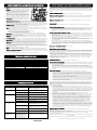
1. ONLINE: The UPS is supplying utility power to connected
equipment.
2. BATTERY: During a severe brownout or blackout, this icon
appears and an alarm sounds (two short beeps followed by
a pause) to indicate the UPS is operating from its internal
batteries. During a prolonged brownout or blackout, the
alarm will beep rapidly every 1/2 second (and the
BATT.CAPACITY meter shows one 20% capacity segment
shaded. The capacity depends on how much load added
and the runtime left.) to indicate the UPS’s batteries are
nearly out of power. You should save files and turn off your
equipment immediately or allow the software to shut the
system down.
3. Energy-Saving: The UPS in energy-saving bypass mode.
See “CyberPower GreenPower UPSTM Technology” section
for more information.
4. LOAD capacity / Sensitivity setup: This meter displays the
approximate output load level (in 20% increments) of the UPS battery outlets. It can also be sensitivity
setup meter if you are in programming mode. It is to control the sensitivity of the UPS to switch to
Battery Mode by selecting UPS shutdown voltage range. When the sensitivity is increased, the UPS will
switch to Battery Mode with less input power variation.
5. BATTERY capacity: This meter displays the approximate charge level (in 20% increments) of the UPS’s
internal battery. During a blackout or severe brownout, the UPS switches to battery power, the
BATTERY icon appears, and the charge level decreases.
6. FAULT: This icon appears if there is a problem with the UPS. Press the POWER button to turn off the
UPS.
- F01: Battery Mode or AC/Utility Power Mode Overload fault (Turn the UPS off and unplug at least
one piece of equipment. Turn on the UPS again.)
- F02: Battery Output Short fault (Contact CyberPower for support.)
- F03: Charger Fault (Contact CyberPower for support.)
- F04: Internal Fault (Contact CyberPower for support.)
7. OVER LOAD: This icon appears and an alarm sounds to indicate the battery-supplied outlets are
overloaded. To clear the overload, unplug some of your equipment from the battery-supplied outlets
until the icon turns off and the alarm stops.
8. SCHEDULE: Users can setup the schedule to turn on and shut down the computer and UPS through
PowerPanel® Personal software. The LCD display will show how much time is left before the UPS will
turn back on or shut down.
9. ESTIMATED RUNTIME: This displays the run time estimate of the UPS with current battery capacity and
load.
10. OUTPUT meter: This meter measure, in real time, the AC voltage that the UPS system is providing to the
computer, such as normal AC line mode, AVR mode, and battery backup mode. (Note: The OUTPUT
meter shows the status of the battery backup outlets in terms of load, frequency, and voltage.)
11. INPUT meter: This meter measures the AC voltage that the UPS system is receiving from the utility wall
outlet. The UPS is designed, through the use of automatic voltage regulation, to continuously correct
output voltage to connected equipment to a safe 110/120 voltage output range. In the event of a
complete power loss, severe brownout, or over-voltage, the UPS relies on its internal battery to supply
consistent 110/120 output voltage. The INPUT voltage meter can be used as a diagnostic tool to identify
poor-quality input power.
12. EVENT: This meter records the number of power outages.
13. MUTE: This icon appears whenever the UPS is in silent mode. The alarm does not beep during silent
mode until the battery reaches low capacity.
14. AVR (Automatic Voltage Regulation): This icon appears whenever your UPS is automatically correcting
low AC line voltage without using battery power. This is a normal, automatic operation of your UPS, and
no action is required on your part.
For more information about functions setup, please refer to the
Function Setup Guide
.
MODEL
CST1500S
Capacity
1500VA / 900W
Nominal Input Voltage
120V
Input Frequency
60 Hz +/- 3 Hz
On-Battery Output Voltage
120Vac +/- 5%
Max. Load for UPS Outlets (5 Outlets)
1500VA / 900W
Max. Load for Full-Time Surge Protection outlets
(10 Outlets)
12 Amp
On-Battery Output Wave Form
Adaptive Sinewave
Operating Temperature
+ 32°F to 104° F / 0° C to 40° C
Operating Relative Humidity
0 to 95% non-condensing
Size (L x W x H)
14.2" x 3.9" x 10.4" (361 x 99 x 264 mm)
Net Weight
24.7lbs / 11.2kg
Battery Type
CyberPower / RB1280X2B
Typical Battery Recharge Time
8 hours from total discharge
Typical Battery Life
3 to 6 years, depending on number of
discharge/recharge cycles
Recommended Battery
Sealed Maintenance Free Lead Acid Battery
Safety Approvals
UL1778, CSA C22.2 No 107.3, FCC/DoC Class B
Problem
Possible Cause
Solution
Circuit breaker button
is projecting from the
back of the unit.
Circuit breaker has tripped
due to an overload.
Turn the UPS off and unplug at least one
piece of equipment. Wait 10 seconds, reset
the circuit breaker by depressing the button,
and then turn the UPS on.
The UPS does not
perform expected
runtime.
Battery not fully charged.
Recharge the battery by leaving the UPS
plugged in.
Battery is worn out.
Contact CyberPower about replacement
batteries.
The UPS will not turn
on.
The on/off switch is designed
to prevent damage from
rapidly turning it off and on.
Turn the UPS off. Wait 10 seconds and then
turn the UPS on.
The unit is not connected to
an AC outlet.
The unit must be connected to a 110/120V
60Hz outlet.
The battery is worn out.
Contact CyberPower about replacement
batteries.
Mechanical problem.
Contact CyberPower.
PowerPanel® Personal
software is inactive (all
icons are gray).
The USB / serial cable is not
connected.
Connect the USB / serial cable to the UPS
unit and an open USB / serial port on the
back of the computer. You must use the
cable that came with the unit.
The USB / serial cable is
connected to the wrong port.
Check the back of the computer for an
additional USB / serial port. Move the cable
to this port.
The unit is not providing
battery power.
Shutdown your computer and turn the UPS
off. Wait 10 seconds and turn the UPS back
on. This should reset the unit.
The serial cable is not the
cable that came with the unit.
Please use the serial cable that came with
the unit for the software.
The USB charging
ports are not providing
power to the
connected devices.
The USB power port has Over
Current Protection design.
When the total current of
connected devices is over
2.1A, the USB charging ports
will stop providing power to
the connected devices.
Turn the UPS off and unplug at least one
piece of device connected to the USB
charging port and then turn the UPS on.
Additional troubleshooting information can be found under “Support” at www.cyberpower.com.
Read the following terms and conditions carefully before using the CyberPower CST1500S (the “Product”).
By using the Product you consent to be bound by and become a party to the terms and conditions of this
Limited Warranty and Connected Equipment Guarantee (together referred to as this “Warranty”). If you do
not agree to the terms and conditions of this Warranty, you should return the Product for a full refund prior to
using it.
Who is Providing this Warranty?
CyberPower Systems (USA), Inc. (“CyberPower”) provides this Limited Warranty.
What Does This Warranty Cover?
This warranty covers defects in materials and workmanship in the Product under normal use and conditions.
It also covers equipment that was connected to the Product and damaged because of the failure of the
Product.
What is the Period of Coverage?
This warranty covers the Product for three years and connected equipment for as long as you own the
Product.
Who Is Covered?
This warranty only covers the original purchaser. Coverage ends if you sell or otherwise transfer the
Product.
How Do You Get Warranty Service?
1. Before contacting CyberPower, identify Your Product model number, the Purchase Date, and each item
of Connected Equipment (E.G. Computer tower, Computer Monitor, Ink Jet Printer, Cable Modem, etc).
2. Visit our web site at http://www.cpsww.com/support or Call us at (877) 297-6937.
3. If your product requires warranty service you must provide a copy of your dated purchase receipt or
invoice.
How Do You Open A Connected Equipment Claim?
1. Call us at (877) 297-6937 or write to us at Cyber Power Systems (USA), Inc., 4241 12th Ave. E., STE 400,
Shakopee, MN 55379, or send us an e-mail message at claims@cpsww.com for instructions, within 10
days of the occurrence.
2. When you contact CyberPower, identify the Product, the Purchase Date, and the item(s) of Connected
Equipment. Have information on all applicable insurance or other resources of recovery/payment that
are available to the Initial Customer and Request a Claim Number.
3. You must provide a dated purchase receipt (or other proof of the original purchase) for the CyberPower
unit and connected equipment. You also need to provide a description of the damage to your
connected equipment.
4. Pack and ship the product to CyberPower and, if requested, the item(s) of Connected Equipment, a
repair cost estimate for the damage to the Connected Equipment, and all claim forms that CyberPower
provides to you. Show the Claim Number on the shipping label or include it with the product. You must
prepay all shipping costs, you are responsible for packaging and shipment, and you must pay the cost of
the repair estimate.
How Long Do I Have To Make A Claim?
All claims must be made within ten days of the occurrence.
What Will We Do To Correct Problems?
CyberPower will inspect and examine the Product.
If the Product is defective in material or workmanship, CyberPower will repair or replace it at CyberPower's
expense, or, if CyberPower is unable to or decides not to repair or replace the Product (if defective) within a
reasonable time, CyberPower will refund to you the full purchase price you paid for the Product (purchase
receipt showing price paid is required).
If it appears that our Product failed to protect any equipment plugged into it, we will also send you forms for
making your claim for the connected equipment. We will repair or replace the equipment that was
damaged because of the failure of our Product or pay you the fair market value (NOT REPLACEMENT COST)
of the equipment at of the time of the damage. We will use Orion Blue Book, or another a third-party
valuation guide, or eBay, craigslist, or other source to establish that amount. Our maximum liability is
limited to $500,000 for the CST1500S.
Who Pays For Shipping?
We pay when we send items to you; you pay when you send items to us.
What isn’t covered by the warranty?
1. This Warranty does not cover any software that was damaged or needs to be replaced due to the failure
of the Product or any data that is lost as a result of the failure or the restoration of data or records, or
the reinstallation of software.
2. This Warranty does not cover or apply to: misuse, modification, operation or storage outside
environmental limits of the Product or the equipment connected to it, nor for damage while in transit or
in storage, nor if there has been improper operation or maintenance, or use with items not designed or
intended for use with the Product, such as laser printers, appliances, aquariums, medical or life support
devices, etc.
What are the Limitations?
The sole and exclusive remedies of the Initial Customer are those provided by this Warranty.
1. This Warranty does not apply unless the Product and the equipment that was connected to it were
connected to properly wired and grounded outlets (including compliance with electrical and safety
codes of the most current electrical code), without the use of any adapters or other connectors.
2. The Product must have been plugged directly into the power source and the equipment connected to
the Product must be directly connected to the Product and not “daisy-chained” together in serial
fashion with any extension cords, another Product or device similar to the Product, surge suppressor,
or power tap. Any such installation voids the Limited Warranty.
3. The Product and equipment connected to it must have been used properly in a suitable and proper
environment and in conformance with any license, instruction manual, or warnings provided with the
Product and the equipment connected to it.
4. The Product must have been used at all times within the limitations on the Product’s VA capacity.
The Product was designed to eliminate disrupting and damaging effects of momentary (less than 1ms)
voltage spikes or impulses from lightning or other power transients. If it can be shown that a voltage spike
lasting longer than 1ms has occurred, the occurrence will be deemed outside the rated capabilities of the
Product and the Limited Warranty is void. CyberPower Does Not Cover or Undertake Any Liability in Any
Event for Any of the Following:
1. Loss of or damage to data, records, or software or the restoration of data or records, or the
reinstallation of software.
2. Damage from causes other than AC Power Line Transients, spikes, or surges on properly installed,
grounded and code-compliant 120 volt power lines in the United States and Canada; transients, surges
or spikes on standard telephone land lines, PBX telephone equipment lines or Base 10T Ethernet lines,
when properly installed and connected. (This exclusion applies, for example, to fluctuations in data
transmission or reception, by CATV or RF transmission or fluctuations, or by transients in such
transmission.)
3. Damage from any circumstance described as excluded above with respect to the Product.
4. Damages from fire, flood, wind, rain, rising water, leakage or breakage of plumbing, abuse, misuse or
alteration of either the product or the Connected Equipment.
5. CyberPower excludes any liability for personal injury under the Limited Warranty and Connected
Equipment Guarantee. CyberPower excludes any liability for direct, indirect, special, incidental or
consequential damages, whether for damage to or loss of property [EXCEPT FOR (AND ONLY FOR)
the specific limited agreement of CyberPower to provide certain warranty benefits regarding
"Connected Equipment" under this Warranty], loss of profits, business interruption, or loss of
information or data. NOTE: Some States or Provinces do not allow the exclusion or limitation of
incidental or consequential damages, so the above limitation may not apply to you.
6. The Product is not for use in high-risk activities or with aquariums. The Product is not designed or
intended for use in hazardous environments requiring fail-safe performance, or for use in any
circumstance in which the failure of the Product could lead directly to death, personal injury, or severe
physical or property damage, or that would affect operation or safety of any medical or life support
device (collectively, "High Risk Activities"). CyberPower expressly disclaims any express or implied
warranty of fitness for High Risk Activities or with aquariums. CyberPower does not authorize use of
any Product in any High Risk Activities or with Aquariums. ANY SUCH USE IS IMPROPER AND IS A
MISUSE OF THE PRODUCT.
Where Can I Get More Information?
The application of the United Nations Convention of Contracts for the International Sale of Goods is
expressly excluded.
CyberPower is the warrantor under this Limited Warranty.
For further information please feel free to contact CyberPower at Cyber Power Systems (USA), Inc. 4241 12th
Ave E., STE 400, Shakopee, MN 55379; call us at (877) 297-6937; or send us an e-mail message at
claims@cyberpowersystems.com.
Cyber Power Systems (USA), Inc. encourages environmentally sound methods for disposal and recycling of
its UPS products.
Please dispose and/or recycle your UPS and batteries in accordance to the local regulations of your state.
All rights reserved. Reproduction without permission is prohibited.
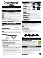
DEFINITIONS FOR ILLUMINATED LCD INDICATORS
TROUBLESHOOTING
TECHNICAL SPECIFICATIONS
  • Page 1 1
  • Page 2 2

CyberPower CST1500S User manual

Category
Uninterruptible power supplies (UPSs)
Type
User manual

CyberPower CST1500S provides uninterrupted power supply and protection for your sensitive electronics. With 1030 joules of surge protection, it safeguards your equipment from voltage spikes and fluctuations. The CST1500S features five battery-powered surge suppression outlets, ensuring temporary power during outages. Advanced Voltage Regulation (AVR) stabilizes inconsistent utility power, preventing damage to your data and hardware. It supports Active PFC power supplies, making it compatible with modern computers.

Ask a question and I''ll find the answer in the document

Finding information in a document is now easier with AI