Page is loading ...

Micro Box
Hardware Manual
Q22, Q22-K1
2016/10/26

www.acti.com
Hardware Manual
2
Table of Contents
Precautions 4
Safety Instructions .................................................................................................... 6
Introduction 7
List of Models ............................................................................................................ 7
Package Contents ..................................................................................................... 8
Physical Description................................................................................................. 9
Mounting Options of Q22 ....................................................................................... 11
Installation Procedures of Q22 12
Step 1: Mount the Bracket ..................................................................................... 12
Step 2: Attach the Camera ..................................................................................... 13
Step 3: Install the Main Unit ................................................................................... 14
Step 4: Connect the Cables ................................................................................... 15
Step 5: Connect to Network ................................................................................... 16
Step 6: Access the Camera Live View .................................................................. 16
Installation Procedures of Q22-K1 17
Step 1: Prepare the Desktop Mount ...................................................................... 17
Step 2: Attach the Camera ..................................................................................... 17
Step 3: Install the Main Unit ................................................................................... 19
Step 4: Connect the Cables ................................................................................... 20
Step 5: Connect to Network ................................................................................... 21
Step 6: Access the Camera Live View .................................................................. 21
Cable Connections 22
Connecting a Power Adapter (Optional) ............................................................... 22
Connecting DI/DO Devices (Optional) .................................................................. 24
Connecting an Audio Out Device (Optional) ........................................................ 27

www.acti.com
Hardware Manual
3
Connecting a Serial Devices (Optional)................................................................ 28
Other Adjustments and Accessories 29
How to Install / Remove the Memory Card ........................................................... 29
How to Insert the Memory Card ................................................... 29
How to Remove the Memory Card ............................................... 30
Accessing the Camera 31
Configure the IP Addresses ................................................................................... 31
Using DHCP Server to Assign IP Addresses ................................ 31
Using the Default Camera IP Address .......................................... 33
Access the Camera ................................................................................................. 35

www.acti.com
Hardware Manual
4
Precautions
Read these instructions
Read all the safety and operating instructions before using this product.
Heed all warnings
Adhere to all the warnings on the product and in the instruction manual. Failure to follow the
safety instructions given may directly endanger people, cause damage to the system or to other
equipment.
Servicing
Do not attempt to service this product yourself as opening or removing covers may expose you to
dangerous voltage or other hazards. Refer all servicing to qualified service personnel.
Trademarks
ACTi and ACTi logo are registered trademarks of ACTi Corporation. All other names and products
used in this manual are registered trademarks of their respective companies.
Liability
Every reasonable care has been taken during the writing of this manual. Please inform your local
office if you find any inaccuracies or omissions. ACTi will not be held responsible for any
typographical or technical errors and reserves the right to make changes to the product and
manuals without prior notice.

www.acti.com
Hardware Manual
5
Federal Communications Commission Statement
This equipment has been tested and found to comply with the limits for a class B
digital device, pursuant to Part 15 of the FCC Rules. These limits are designed
to provide reasonable protection against harmful interference in a residential
installation. This equipment generates, uses, and can radiate radio frequency energy and, if not
installed and used in accordance with the instructions, may cause harmful interference to radio
communications. However, there is no guarantee that interference will not occur in a particular
installation. If this equipment does cause harmful interference to radio or television reception,
which can be determined by turning the equipment off and on, the user is encouraged to try to
correct the interference by one or more of the following measures:
Reorient or relocate the receiving antenna.
Increase the separation between the equipment and receiver.
Connect the equipment into an outlet on a circuit different from that to which the
receiver is connected.
Consult the dealer or an experienced radio/TV technician for help.
Warning: Changes or modifications to the equipment that are not expressly approved by the
responsible party for compliance could void the user’s authority to operate the equipment.
European Community Compliance Statement
This product has been tested and found to comply with the limits for Class B
Information Technology Equipment according to European Standard EN 55024
and EN 55032. In a domestic environment, this product may cause radio interference in which
cause the user may be required to take adequate measures.

www.acti.com
Hardware Manual
6
Safety Instructions
Cleaning
Disconnect this product from the power supply before cleaning.
Accessories and Repair Parts
Use only the accessories and repair parts recommended by the manufacturer. Using other
attachments not recommended by the manufacturer may cause hazards.
Installation
Install the main unit and other devices (such as PoE injector, alarm, etc.) that will be used with the
camera in a dry place protected from weather,
Servicing
Do not attempt to service this product yourself. Refer all servicing to qualified service personnel.
Damage Requiring service
Disconnect this product from the power supply immediately and refer servicing to qualified
service personnel under the following conditions.
1) When the power-supply cord or plug is damaged
2) If liquid has been spilled, or objects have fallen into the product.
3) If the inner parts of product have been directly exposed to rain or water.
4) If the product does not operate normally even by following the operating instructions in this
manual. Adjust only those controls that are covered by the instruction manual, as improper
adjustment of other controls may result in damage, and will often require extensive work by a
qualified technician to restore the product to its normal operation.
Safety Check
Upon completion of any service or repairs to this product, ask the service technician to perform
safety checks to determine if the product is in proper operating condition.

www.acti.com
Hardware Manual
7
Introduction
List of Models
This hardware manual contains the following models:
Q22
2MP Outdoor Micro Box with Basic WDR, SLLS, Fixed
lens
Q22-K1
2MP Outdoor Micro Box with Basic WDR, SLLS, Fixed
lens
From the installation perspective, the above models are very similar; therefore one manual is
used for all of them.

www.acti.com
Hardware Manual
8
Package Contents
Check if the camera package comes with the following items:
Camera
Main Unit
Mounting Rail
Bracket (Q22 only)
PMAX-0901 (Q22-K1 only)
PMAX-1110 (Q22-K1 only)
Terminal Block
(for DI/DO)
Terminal Block
(for RS-232)
Terminal Block
(for Power)
Camera Set Screws
Quick Installation Guide
Warranty Card
IMPORTANT: When the camera is taken out from the box, the lens cover is covered by a thin film.
DO NOT remove this film. It is used to protect the lens cover from scratches or fingerprint marks
which may happen during installation. Remove this film after the camera is securely installed
and all connections are complete.

www.acti.com
Hardware Manual
9
Physical Description
Item
Description
1
Camera Module
This is the camera lens module.
2
Built-in Microphone
Use for audio recording.
3
LED Indicators
Power LED (PWR): Lights BLUE to indicate power is
connected.
Link LED (LINK): Lights GREEN to indicate network is
connected.
Activity LED (ACT): Flashes AMBER to indicate network
activity is in progress.
4
Memory Card Slot
Insert a memory card (not included) into the slot for local
recording purposes. See How to Install / Remove the Memory
Card on page 29 for more information.
NOTE: Supports only microSDHC and microSDXC cards.
5
Digital Input / Output
Connects to digital input or output devices, such as an alarm
trigger, panic button, etc. Digital Input (DI) and Digital Output
(DO) devices are used in applications like motion detection,
event triggering, alarm notifications, etc. See Connecting DI/DO
Devices (Optional) on page 24 for information.
6
Camera Port
Connects the camera to the main unit.

www.acti.com
Hardware Manual
10
Item
Description
7
Audio Input / Output
Connects the built-in microphone and an audio output device,
such as speakers. See Connecting an Audio Out Device
(Optional) on page 27 for more information.
8
Ethernet Port
Connects to a network using an Ethernet cable.
9
Serial Port
Connects to serial device using the RS-232 protocol. See
Connecting a Serial Devices (Optional) on page 28 for more
information.
10
DC 12V Power Input
In case the camera is connected to a non-PoE (Power over
Ethernet) switch, use this connector to connect the camera to an
external power adapter. See Connecting a Power Adapter
(Optional) on page 22 for more information.
11
Reset Button
Restores the factory default settings of the camera. To reset the
camera, while the power is on, press and hold the Reset Button
for at least 5 seconds or until the Power LED goes off.

www.acti.com
Hardware Manual
11
Mounting Options of Q22
Below are several mounting options that you can use to install the camera. Select the most
suitable solution for your installation environment.
Mount Types
Accessories
Desktop Mount
The camera is placed on counter tops, desktops, etc. using the Desktop
Magnetic Base and Gooseneck. Ideal for close-up video and audio
recording.
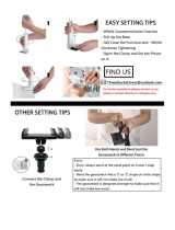
Edge Clamp
The camera can be mounted on any flat edges like desks, partitions,
shelves, etc. using the Edge Clamp. The optional Gooseneck can also
be attached to provide flexibility and extend the camera farther from the
edge.
Pole Mount
The camera can be mounted on a horizontal pole to provide close-up
video and audio recording ideal for customer service applications.
NOTE:
For more information about the mounting solutions and accessories, please check the
Mounting Accessory Selector in our website (http://www.acti.com/mountingselector).
The above mounting accessories are not included in the package. Contact your sales
agents to purchase.

www.acti.com
Hardware Manual
12
Installation Procedures of Q22
Before installation, determine the location to mount the camera and the main unit. The main unit
can be installed apart from where the camera is mounted, but should be close enough. Consider
that the camera cable is 3 meters long. Although the camera module is waterproof, the main unit
is not so it should be installed indoors.
This section describes procedures in mounting the camera on the ceiling. Similar procedures
apply when mounting on walls.
NOTE:
There is a plastic film protecting the lens. Do not remove the plastic film until the
installation is complete. However, the plastic film has been removed on the camera
images in this documentation to capture them more clearly.
The camera images on this documentation are for reference only and may be
different from the actual camera.
Step 1: Mount the Bracket
NOTE: Before installing the bracket, make sure the ceiling or wall can bear more than the weight
of the camera and its accessories.
Install the bracket to the ceiling or wall using the three (3) screws included in the bracket
package.

www.acti.com
Hardware Manual
13
Step 2: Attach the Camera
The camera has two (2) installation screw holes, located on the rear or the bottom side of the
camera module, where the bundled bracket can be mounted onto. Use the rear screw hole for
ceiling installation while the bottom screw hole for wall installation.
NOTE: The following procedures show how to mount the bracket on the ceiling using the rear
screw hole. Similar procedures apply when attaching the bracket to the bottom side for wall
installation.
1. Attach the camera to the bracket through the screw hole on the rear of the camera module.
2. Loosen the knob and adjust the camera angle.
3. Route the camera cable towards the main unit.
4. Remove the thin film covering the lens.
Knob

www.acti.com
Hardware Manual
14
Step 3: Install the Main Unit
NOTE: Although the camera module and lens are already waterproof, the main unit is not and
should be installed indoors. Use a third party junction box with cable gland to protect the main
unit and cable connections against outdoor conditions.
1. Install the mounting rail on the surface using the two (2) screws.
2. Attach the lower end of the main unit to the mounting rail.
3. Slightly push up the main unit and snap the upper end into place.
2
3

www.acti.com
Hardware Manual
15
Step 4: Connect the Cables
1. Connect the camera cable connector to the Camera port of the main unit.
2. Connect the Audio terminal block to the Audio port of the main unit.
3. For excess cable, properly roll the cable as shown below; do not bend the cable.
Camera Cable
Audio

www.acti.com
Hardware Manual
16
Step 5: Connect to Network
1. Connect one end of a network cable to the Ethernet port of the main unit.
2. Connect the other end to a switch or injector. Then, connect the switch or injector to a
network or PC and a power source. See Power-over-Ethernet (PoE) example connection
diagram below.
Network
AC Power
Source
PoE Injector /
PoE Switch
Power Cable
Ethernet Cable
Ethernet Cable
(Data + Power)
Ethernet Cable
(Data)
Main Unit
In case of using a non-PoE switch, power up the camera using a power adapter (not
supplied). See Connecting a Power Adapter (Optional) on page 22 for more information.
3. As needed, connect and power up other devices, such as digital input/output, audio, or serial
device. See Connecting DI/DO Devices (Optional) on page 24 for more information on
connecting other devices.
Step 6: Access the Camera Live View
See Accessing the Camera on page 31 for more information on how to access the Live View of
the camera.

www.acti.com
Hardware Manual
17
Installation Procedures of Q22-K1
Before installation, determine the location to mount the camera and the main unit. The main unit
can be installed apart from where the camera is mounted, but should be close enough, like under
the desk. Consider that the camera cable is 3 meters long. Although the camera module is
waterproof, the main unit is not so it should be installed indoors.
This section describes procedures in mounting the camera on the desktop.
NOTE:
There is a plastic film protecting the lens. Do not remove the plastic film until the
installation is complete. However, the plastic film has been removed on the camera
images in this documentation to capture them more clearly.
The camera images on this documentation are for reference only and may be
different from the actual camera.
Step 1: Prepare the Desktop Mount
Attach the gooseneck to the magnetic base.
Step 2: Attach the Camera
The camera has two (2) installation screw holes, located on the rear or the bottom side of the
camera module, where the gooseneck can be mounted onto.
NOTE: The following procedures show how to mount the bracket on the desktop mount using the
bottom screw hole. Similar procedures apply when attaching the bracket to the rear side hole.

www.acti.com
Hardware Manual
18
1. Attach the camera to the gooseneck through the screw hole on the bottom of the camera
module.
2. Route the camera cable along the gooseneck and attach it in place with the bundled Velcro
strap(s).
3. Bend the gooseneck to tilt or adjust the viewing position of the camera.
4. Route the camera cable towards the main unit.
5. Remove the thin film covering the lens.

www.acti.com
Hardware Manual
19
Step 3: Install the Main Unit
Although the camera module is waterproof, the main unit is not and should be installed indoors.
1. Install the mounting rail on the surface using the two (2) screws.
2. Attach the lower end of the main unit to the mounting rail.
3. Slightly push up the main unit and snap the upper end into place.
2
3

www.acti.com
Hardware Manual
20
Step 4: Connect the Cables
1. Connect the camera cable connector to the Camera port of the main unit.
2. Connect the Audio terminal block to the Audio port of the main unit.
3. For excess cable, properly roll the cable as shown below; do not bend the cable.
Camera Cable
Audio
/