Duerkopp Adler 527 User manual
- Category
- Sewing machines
- Type
- User manual

Instructions for setting individual mechanisms
527
Minerva Boskovice, a.s., Sokolská 60, CZ - 680 17 Boskovice
Tel.: +420-516 453434, 453433, 494111 Fax: +420-516 452165 http://www.minerva-boskovice.com
Edition: 01/2004 Printed: Czech Republic

Contens - Instructions for setting individual:
1. General safety instructions.............................................................................................................................................. 1
2. Introduction ........................................................................................................................................................................ 1
3. Setting of the feeder height above the throat plate.................................................................................................... 2
4. Setting of the needle and feeder movement ................................................................................................................ 2
5. Mounting of the throat plate ............................................................................................................................................ 2
6. Setting of the elliptical path of the feeder ................................................................................................................... 2
7. Setting of the feeding length .......................................................................................................................................... 3
8. Presser foot replacement ................................................................................................................................................. 3
9. Presser foot lifting setting ............................................................................................................................................... 3
10. Setting of the needle bar height ..................................................................................................................................... 3
11. Adjustment of the hook timing ........................................................................................................................................ 4
12. Setting of the middle part of the hook holder .............................................................................................................. 4
13. Setting of the opening hook of the hook ....................................................................................................................... 5
14. Dismounting and mounting of the driving belt ............................................................................................................ 5
15. Setting the needle punch into the middle of the needle groove
in the throat plate in longitudinal direction................................................................................................................. 6
16. Setting of the needle punch into the middle of the needle groove
in the throat plate in transversal direction ................................................................................................................... 6
17. Setting of the zigzag stitch shifting................................................................................................................................6
18. Setting of the controlling force of the zigzag stitch adjusting .................................................................................. 7
19. Taking up of the teeth clearance in the zigzag stitch gearing................................................................................... 7
20. Setting of the needle bar and of the hook shaft position........................................................................................... 8
21. Time setting of the control cam of the thread cutter................................................................................................... 8
22. Setting of the movable cutting knife lifting.................................................................................................................. 9
23. Setting of the upper thread tensioner releasing.......................................................................................................... 9
24. Setting of the adjusting spring function ....................................................................................................................... 9
25. Setting of the starting position of the movable thread cutter ................................................................................... 9
26. Setting of the stationary knife presure .......................................................................................................................... 9
27. Setting of the stop in the top position of the needle .................................................................................................. 1 0
28. Making an upper thread reserve ..................................................................................................................................... 1 0
29. Dismounting and mounting of the plate........................................................................................................................ 1 0
30. Dismounting and mounting of the movable cutting knife.......................................................................................... 1 0

1
Instructions for setting individual mechanisms
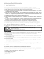
1. General safety instructions
The non-observance of the following safety instructions can cause bodily injuries or damages to the machine.
1. The machine must only be commissioned of the instruction book and operated by persons with appropriate training.
2. Before putting into service also read the safety rules and instructions of the motor supplier.
3. The machine must be used only for the purpose intended. Use of the machine without the safety devices is not permitted.
Observe all the relevant safety regulations.
4. When gauge parts are exchanged (e.g. needle, top roller, needle plate, feed dog and bobbin) when treading, when the
workplace is left, and during service work, the machine must be disconnected from the mains by switching off the master
switch or disconnecting the mains plug.
5. Daily servicing work must be carried out only by appropriately trained persons.
6. Repairs, conversion and special maintenance work must only be carried out by technicians or persons with appropriate
training.
7. For service or repair work on pneumatic systems the machine must be disconnected from the compressed air supply system.
Exceptions to this are only adjustments and functions checks made by appropriately trained technicians.
8. Work on the electrical equipment must be carried out only by electricians or appropriately trained persons.
9. Work on parts and systems under electric current is not permitted, except as specified in regulations DIN VDE 0105.
10. Conversion or changes to the machine must be authorized by us and made only in adherence to all safety regulations.
11. For repairs, only replacement parts approved by us must be used.
12. Commissioning of the sewing head is prohibited until such time as the entire sewing unit is found to comply with EC
directives.
It is absolutely necessary to respect the safety instructions marked by these signs.
Danger of bodily injuries !
Please note also the general safety instructions.
IMPORTANT WARNING
In spite of all safety measures made on the machines, inappropriate actions of the operator may lead to dangerous situations. In
industrial sewing machines, attention should be paid to the following still remaining possible sources of injury:
1. Moving sewing needle
- risk of injury when sewing with raised pressure foot or top roller, because the finger guard is then positioned too high.
2. Moving thread take-up lever
- risk of injury when inadvertently or intentionally inserting the finger(s) between the thread take-up lever and its guard.
3. Moving pressure member
- risk of injury when holding sewn work in immediate vicinity of the pressure member and beginning to insert under the
pressure member a considerably thicker sewn work portion,
- risk of injury when sinking the pressure member.
4. When switched off, the clutch motor slows down by inertia but would be reactivated by an accidental treading down of the
motor treadle. To avoid such risk, it is advised to hold the handwheel by hand and slightly to depress the motor treadle.
2. Introduction
This part contains instruction for regulating the mechanisms of the sewing machine head.
For setting the machine, simple setting aids are used which are included in the accessory of the machine. Besides these aids,
universal measuring devices are used, such as slide calliper, feeler gauges and dynamometer for measuring the thread tension.
It is adviceable to order the locating fixture S791 947001 for setting:
- the feeder planeness and and height
- the hook timing
- the hook medium part holder
- presser foot lifting

2
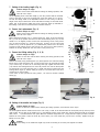
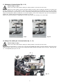
3. Setting of the feeder height above the throat plate (Fig. 1, 2, 3)
Caution! Danger of injury!
Switch off the main switch! Before starting the setting operation, wait until the motor stops!
The height of the feeder teeth (11) above the throat plate (10) is to be set within the extent of 0.8 – 1.2 mm according to the nature
of the sewn material. The setting thereof is to be done in loosening the screw (2) of the lifting lever (8) on the shaft (6) and in
setting the necessary height of the feeder teeth. Tighten firmly the screw. The evenness of the teeth can be set using the eccentric
pin (5) in loosening the screw (1) in the feeding lever (9) on the shaft (7) and, in turning a bit the pin (5) set the feeder at the level
of the throat plate. Tighten then the screw (1).
Check the height and the planeness of the feeder teeth using the locating fixture (12).
The figure 2 shows the method of using of the locating fixture for checking the planeness and height of the feeder teeth 0.8 mm
above the throat plate. The figure 3 shows the method of using of the locating fixture for checking the planeness and height of
the feeder teeth 1.2 mm above the throat plate.
4. Setting of the needle and feeder movement
Caution! Danger of injury!
Switch off the main switch! Before starting the setting operation, wait until the motor stops!
In turning by hand the hand wheel, set the feeder into the position, where the feeding ends and where the feeder teeth are at the
level of the throat plate. Loosen two screws on the lower belt wheel and turn a bit the hand wheel until the needle point, when
moving downward, is set about 5 mm above the throat plate, and tighten the screws on the belt wheel.
5. Mounting of the throat plate (Fig. 1)
Caution! Danger of injury!
Switch off the main switch! Before starting the setting operation, wait until the motor stops!
The throat plate (10) must be correctly placed and tightened by the screws (3) in such a way, so that the needle passes through
the centre of the needle hole. The needle hole should not be damaged or abraded by the needle or thread, eventually otherwise
damaged. Each damage of this kind influences on the quality of sewing.
6. Setting of the elliptical path of the feeder (Fig. 1)
Caution! Danger of injury!
Switch off the main switch! Before starting the setting operation, wait until the motor stops!
With a correctly set machine the feeder describes an elliptical path in both feeding directions. We proceed to the respective
setting as follows: The adjustable eccentric is set by means of a pin into the hole in the bottom shaft and determines the size of
the feeding length. The second (fixed) eccentric situated in front of the adjustable eccentric determines the correct ellipse. The
fixed eccentric is secured with two screws which are placed in its collar.
The eccentric is of a constant eccentricity, so that the height of the ellipse remains the same with different setting of the height
of the feeder teeth. With a zero eccentricity of the adjustable eccentric (i.e. with a zero feeding), we set the feeder holder with the
feeder in the centre of the slot in the throat plate with the loosened screws (4) of the lever (9) on the feeding shaft (7).
It is necessary to observe the principle that the maximum feeder lifting is about in the middle of the feeding path.
3
11
10
3
6
82
1
5
9
7
4
Fig. 1
Fig. 2 Fig. 3
12

3
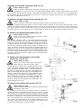
7. Setting of the feeding length (Fig. 4)
Caution! Danger of injury!
Switch off the main switch! Before starting the setting operation, wait
until the motor stops!
On the regulating knob of the stitch length (1) the zero position with the loosened
screw of the lever on the pin of the hand lever of the back stitch (2) is to be set.
Set now the sliding sleeve of the adjustable eccentric in such a way, so that the
height of the ellipse remains the same with different setting of the feeder teeth
height. and, in this position, tighten the screw of the lever. Check up thereafter, if
the feeding is the same in the forward and rearward direction.
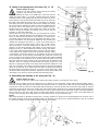
8. Presser foot replacement (Fig. 5)
Caution! Danger of injury!
Switch off the main switch! Before starting the setting operation, wait
until the motor stops!
When replacing the presser foot (1), switch off the stop motor, lift first the pressure
bar (11) into its top position and secure it with the hand lifting lever (12). Lift the
needle too in its highest position.Loosen then the fastening screw of the presser
foot (5) with the washer (7), dismount the finger protector (9) and remove the
presser foot (1) from the presser bar (11). Remount the presser foot in an inverse
procedure. After having fixed a new presser foot, check up (in lifted position),
whether the moving needle bar does not strike on the presser foot.
9. Presser foot lifting setting (Fig. 5, 6, 8)
Caution! Danger of injury!
Switch off the main switch! Before starting the setting operation, wait
until the motor stops!
Remove the needle, Using the lifting lever (12) lift the presser foot. Place the locating
fixture (Fig. 6) under the presser foot. Loosen the the screw (14) and shift the guide
(15) in such a way, so that it fits on the lifting sheet (16). Tighten then the screw
(14). Remove the locating fixture and lower the presser foot onto the throat plate.
Lift the presser foot using the knee lever or pedal and check its lifting using the
locating fixture (Fig.6, 8). Further setting of the lift is to be done with a lever in an
oil bath and on the arm web.
In the event of other presserfoot lifting values , we shall use another suitable
setting jig.
10. Setting of the needle bar height (Fig. 5)
Caution! Danger of injury!
Switch off the main switch! Before starting the setting operation, wait until the motor stops!
The hook together with the needle must be set in such a way, so that, at the moment when the hook point picks up the loop of the
upper thread, the top edge of the needle eye is in the lefthand position of the needle bar, with the maximum width of the zigzag
stitch, about 0,6 mm below the hook point. When the needle bar height does not comply with this request, proceed as follows:
Remove the front guard. Loosen the screw (6) of the carrier (13) of the needle bar (10) and set it correctly. Tighten screw (6).
Mount the front guard.
Caution !
An incorrect setting of the needle bar height may cause the striking of the hook point against the needle.
Fig. 4
1
2
Fig. 5
6
12
13
4
2
11
7
5
4
3
10
9
1
Fig. 6
Fig. 8
15
14
16

4
11. Adjustment of the hook timing (Fig. 9, 10)
Caution! Danger of injury!
Switch off the main switch! Before starting the setting operation, wait until the motor stops!
Set a zero zigzag sitch on the machine. Turn the hand wheel towards ourselves, until the needle bar descends in its lowest point
and then ascends by 2.8 + 0.2 mm upwards. In this position, the hook point must be on the needle axis. The max. space between
the needle and the hook is to be 0.05 mm. If it is not so, dismount the throat plate proceed to the correct setting of the hook timing
using the locating fixture. When the needle bar is in its lowest position, screw on the locating fixture (Fig. 9) onto the needle bar
together with gauges giving the hook timing size, namely 2.8 + 0.2 mm.
Secure the correct hook position in tightening the screws and proceed to the mounting of the throat plate.
12.Setting of the middle part of the hook holder (Fig. 11, 12)
Caution! Danger of injury!
Switch off the main switch! Before starting the setting operation, wait until the motor stops!
Set the middle part hook holder (7) in such a way, so that the space between the holder nose and the bottom of the groove of the
middle hook part is about 0.7 mm. Proceed to this setting after having loosened the holding screw (10) using a locating jig (Fig.
11) - see equipments part A, par. 4.2, 4.4.
Fig. 9 Fig. 10
10 7
Fig. 11

5
Fig. 12
4
1
7
8
5
6
2
9
3
10
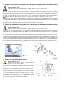
13. Setting of the opening hook of the hook (Fig. 12, 13)
Caution! Danger of injury!
Switch off the main switch! Before starting the setting
operation, wait until the motor stops!
The space between the sides of the middle part of the hook and the
middle part hook holder (7) is forcibly produced during the machine
running by means of the opening hook (8) and the eccentric (6) for an
easier passing of the thread between the middle part of the hook and
the holder of the middle part of the hook (7). This setting is to be done
after having set the zero zig-zag stitch. Set first the opening size, namely
the space produced between the holder of the hook middle part and
the groove sides in the middle part of the hook. Together with this
setting proceed to the setting of the opening hook, namely to the axial
clearance taking up between the opening hook nose (8) and the
projection on the hook middle part.
Unscrew first four screws (3) on the cover (9) of the hook box, remove
the cover and withdraw therefrom the lubricating insert. Loosen the
screw (1) which secures the position of the sleeve (5), on which the pin
(4) with the opening hook bears on. Set the bobbin case lifter in such
a way, so that there is 0.8 mm clearance between its nose and the hook
medium part and tighten the screw (1). Loosen at the same time the
screw (11) and set the opening hook in such a way, so that it forms
with the projection of the hook middle part the clearance of 0.5 mm
necessary for the thread passage. After having set the opening hook
tighten the screw (11) with the maximum eccentric turning. This setting
is to be done with the removed throat plate. Proceed to the time setting
of the opening hook against the the hook during the running-in phase
of the machine. Loosen two screws (2) on the eccentric (6) and, in turning it a bit
on the bottom shaft, set the opening of the middle part of the hook in such a way,
so that it begins at the moment, before the upper thread starts passing between
the groove sides in the middle part of the hook and the hook holder nose. At the
same time check the correct passage of the upper thread over the maximum hook
diameter, when the opening hook approaches the opening projection for the
purpose of opening the passage of the upper thread around the middle part of the
hook. The correctness of this setting can be best checked in observing the adjusting
spring on the tensioner of the upper thread. Be careful in having free passage of
the thread when the adjusting spring has to produce in this phase only a slight
movement. After having set the eccentric, tighten the screws and proceed to the
remounting of the hook box guard including the lubricating insert.
14. Dismounting and mounting of the driving belt (Fig. 14)
Caution! Danger of injury!
Switch off the main switch! Before starting the setting operation, wait until the motor stops!
Dismount first the position sensor (A). When there is no marking of the synchronizer position against the hand wheel, mark it.
Dismount the upper belt guard (2) after having unscrewed the screws (1). Remove the V-belt from the hand wheel.After having
loosened two screws (3) shift out the hand wheel with the bearing )4) from the machine arm and from the upper shaft (5). Pull the
driving belt (6) through the hole in the machine arm and around the upper shaft and put it on both belt wheels. Remount the hand
wheel on the upper shaft in such a way, so that the first screw (3) in the direction of the hand wheel rotation, after being tightened,
bears on the flat on the upper shaft. Secure the hand wheel with the second screws (3). Put the V-belt on the hand wheel and
proceed to the mounting of the belt guard and of the position sensor up to the position mark.
Notice!
After having mounted or replaced the driving belt, it is always necessary to proceed to the timing adjustment of the hook. and of
the feeding according to the above paragraphs. When the mounting is not done by any skilled mechanician, then we recomend
to remove the needle from the needle bar before starting the mounting.
3
Fig. 14
A
4
1
2
56
0,5
0,8
8
Fig. 13
11
Middle part of
the hook

6
Fig. 17
4
5
6
1
23
15.Setting the needle punch into the middle of the needle groove in the throat plate in longitudinal direction
(Fig. 5)
Caution! Danger of injury!
Switch off the main switch! Before starting the setting operation, wait until the motor stops!
This setting is to be done after having set the zero zigzag stitch. In turning the hand wheel set the needle bar with the needle into
its bottom position. The needle is to stand in the middle of the needle groove both in the longitudinal and in the transversal
direction. When this is not so in the longitudinal direction (in the direction of feeding the sewn material), remove the front guard
after having unscrewed two fastening screws and loosen the securing screws (2) and (3). Now it is possible, by a fine turning of
the screws (4) on the front and on the rear side of the arm, to set the needle into the middle of the groove in the throat plate in
the longitudinal direction Tighten thereafter the screws (2) and (3) and proceed to the mounting of the front guard.
Notice!
When setting the needle position in the throat plate, not tighten fully the adjusting screws (4). Between these screws and the
needle bar holder there must be let a minimum clearance, so that the side movement of the needle bar holder with the zigzag stitch
is without any resistance. Without observing the necessary clearance between the adjusting screws (4) and the needle bar holder
the mechanism may be damaged. Check up the space between the hook point and the needle.
16.Setting of the needle punch into the middle of the needle groove in the throat plate in transversal direction
(Fig. 15, 16)
Caution! Danger of injury!
Switch off the main switch! Before starting the setting operation, wait until the motor stops!
This setting is to be done after having set the zero zigzag stitch. In turning the hand wheel set the needle bar with its needle in its
bottom position. The needle should stand in the middle of the needle groove both in the transversal and in the longitudinal
direction. When it is not so, remove the guard (1) from the front part of the arm after having unscrewed the screw (2) and the plug
from the rear opposite part of the arm. Loosen thereafter both screws (3) and set the complete needle bar holder (4) in such a way,
so that the needle is in the middle of the groove of the throat plate in transversal direction. After having set this, tighten the screws
(3) and proceed to the mounting of the guard and the plug. Check up the needle punch with the maximum stitch width and bear
in mind to have a clearance between the needle and the groove side in both needle positions. When turning the hand wheel and
with the set zero zigzag stitch, the needle bar with the needle should not perform any side movement. If it is so, then it is necessary
to set the basic zero position of the driving mechanism of the zigzag stitch. But this setting is of a larger extent, it needs more time
and is to be done by a mechanician with a good knowledge of the machine having some practice in the sewing machines line.
17.Setting of the zigzag stitch shifting (Fig. 17)
Caution! Danger of injury!
Switch off the main switch! Before starting the setting
operation, wait until the motor stops!
With the correctly set up machine, the needle bar shifts with the maximum
zigzag stitch width at the moment, when the needle is about 4 mm above
the throat plate and its path (shifting) is symmetrical against the axis of
the groove in the throat plate. Proceed to the necessary setting after
having unscrewed four screws (6) and after having removed the guard
(1). Loosen the screws (2) of the toothed wheel (3) on the upper shaft
(4). Turn the hand wheel and change the mutual position of the upper
shaft (4) and the wheel (3). After having moderately tightened check the
needle shifting. After having attained the correct needle shifting tighten
the screws (2) and proceed to the mounting of the guard.
Fig. 15
Fig. 16
2
1
3
4
3

7
18. Setting of the controlling force of the zigzag stitch adjusting (Fig. 18, 19)
Caution! Danger of injury!
Switch off the main switch! Before starting the setting operation, wait until the motor stops!
To get a continuous tilting of the slot link of the zigzag stitch (19) there is placed in the insert (10) the braking roller (1) with the
spring (5) and with the regulating screw (8). In turning the screw to the right, the pressure upon the roller increases in increasing
so the force necessary for setting the zigzag stitch width. The proper securing of the zigzag stitch setting is done by means of a
arresting mechanism controlled by the lever (7). Proceed to any setting of the zigzag stitch width only after having loosened this
lever in turning it to the left. The zigzag stitch width is set by shifting the lever (2). In its zero position (up to the stop) the zigzag
stitch width is zero, in shifting the lever to the right it is increased up to 10 mm. The numerical designation on the guard (16)
corresponds approximately to the set values. The shifting force is regulated after having withdrawn the complete zigzag stitch
mechanism from the web of the arm. Unscrew first two screws (17) on this mechanism and remove the guard (16) therefrom.
Unscrew three fastening screws (3) from the body of the zigzag stitch mechanismu. Unscrew the lock screw (18) on the pin (20)
and pull this pin out from the guide (19). Loosen the arresting lever (7) and disengage the pin (21). In this way the body of the
zigzag stitch mechanism is loosened to be removed from the machine arm. The remounting thereof is done in the inverse
procedure.
Fig. 18 Fig.19
19
20
18
21
16
17
9
10
3
7
23
6
5
1
8
4
19. Taking up of the teeth clearance in the zigzag stitch gearing (Fig. 17, 18)
Caution! Danger of injury!
Switch off the main switch! Before starting the setting operation, wait until the motor stops!
For taking up the teeth clearance in the zigzag stitch gearing there serves the eccentric pin (6, Fig. 18). If we want to change the
clearance, we must dismount first the upper guard (1, Fig. 17) after having unscrewed four fastening screws (6, Fig. 17). After
having loosened the screw (5, Fig. 17) which is placed on the riser in the arm space, proceed, in turning a bit the eccentric pin (6,
Fig. 18), to taking up of the teeth clearance in the zigzag stitch gearing, namely between the toothed wheel on the complete cam
and the toothed wheel (3, Fig. 17) on the upper shaft. Secure the adjusted position by tightening orderly the screw (5, Fig. 17).

8
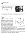
20.Setting of the needle bar and of the hook shaft position (Fig. 20, 21)
Caution! Danger of injury!
Switch off the main switch! Before starting the setting operation, wait until the motor stops!
After a larger repair of the machine it is suitable to check up the mutual position of the needle bar in its central position and that
of the hook shaft. The axis of the hook shaft is shifted to the left from the axis of the needle bar. Proceed to the respective setting
after having loosened two screws (3), which secure the clamping joint between the bedplate and the hook gearbox. In its correct
position, the hook gearbox is pushed to the riser of the bed plate and the axis of the hook shaft is parallel with the plane of the
bedplate. Secure the box position in tightening both screws (3).
Notice!
In case of dismounting the hook gearbox it is necessary to respect, when remounting it, the parallelism of the axis of the hook
shaft with the plane of the bed plate. This parallelism is measured e.g. by means of two shafts, which we place on the top surface
of the bedplate and on the machined surface of the gearbox. We check up this parallelism in measuring the value (B).
21.Time setting of the control cam of the thread cutter
(Fig. 22)
Caution! Danger of injury!
Switch off the main switch! Before starting the setting
operation, wait until the motor stops!
For a safe and correct thread catching under the throat plate it is
neces-sary to set the correct position of the control cam which is
placed on the bottom shaft. From this cam, the movement of the
thread wiper derived for catching the upper and bottom thread
including its cutting, and the mechanisme of the tensioner. With
the machine switched off, tilt the machine head and, using the
hand wheel, set the take-up lever into its top position. Loosen
two screws (1) of the cam (2) and set the loosened cam in such a
way, so that we set the gauge mark on the cam (marked with
colour) into the axis of the pin (3) and secure the cam anew by the
screws (1). This position is to be taken as a basic setting of the
cam and it is necessary to eventually reset it according to the
thread or sewn material type. The start of the thread wiper
movement is to be set in slight turning of the cam on the bottom shaft. Push the lever (4), in this way the pin (3) is put into the
straight course of the groove. In turning the hand wheel in the direction towards the sewer (in counter-clockwise direction) check
the start of the movement of the thread wiper from the starting into the rear position.
Check the correct position of the thread wiper as follows:
At the moment when the loop of the upper thread and the bottom thread will leave the knocking-over slide of the hook and form
so a characteristic triangle, the point of the thread wiper should be in its close vicinity. When further turning the hand wheel, the
point of the thread wiper must pass through the triangle (one branch of the upper thread loop, bottom thread on one side of the
thread wiper and the other upper thread loop branch on the other side of the thread wiper). The thread lying on the side of the
wiper provided with a cutout, must fit into this cutout.
After having loosened two screws (1) on the cam (2) set the start of the thread wiper movement. In turning the cam in the direction
of the bottom shaft rotation the start of the thread wiper is accelerated and, inversely, it is delayed. After having set up the cam,
check whether the pin (3), after pushing on the lever (4), fits easily onto the straight part of the cam (2) groove. Push the carrier
ring (5) to the cam set up in this way and tighten it up with the screws (6) on the bottom shaft.
B
3
Fig. 20
Fig. 21
Fig. 22
512 3
4
698
7
13
12
11
10

9
22. Setting of the movable cutting knife lifting (Fig. 22)
Caution! Danger of injury!
Switch off the main switch! Before starting the setting operation, wait until the motor stops!
After having engaged the pin (3) into the cam (2), turn the hand wheel towards ourselves, until the bottom thread and one branch
of the loop enter into the cutout on the side of the cutting knife. When this does not occur, loosen the nut (7) on the tilting lever
(8) and shift the draw bar (9) in the groove of the lever (8). To increase the movement, the lever arm is to be lenghtened. Secure
the position in tightening up the nut (7).
23. Setting of the upper thread tensioner releasing (Fig. 22)
Caution! Danger of injury!
Switch off the main switch! Before starting the setting operation, wait until the motor stops!
The cutting mechanism needs that, within its course, the upper thread is released i.e. that the main thread tensioner is to be
released. It is automatically released within the necessary cutting cycle through the cable (13) and the lever system when starting
the cutting operation. If there no release thereof occurs, it is necessary to set the tension of the cable (13). This is done when
loosening the screw (11) on the lever (12) or in turning slightly the whole lever (12) after having loosened the screw (10).
24. Setting of the adjusting spring function (Fig. 23)
Caution! Danger of injury!
Switch off the main switch! Before starting the setting
operation, wait until the motor stops!
After having loosened the screw (1) remove the complete upper thread
tensioner from the machine arm. The size of the elasticity of the adjusting
spring (2) is to be set after having loosened the screw (3) on the sleeve (4)
in turning slightly the pin (5) using a screwdriver. In turning the pin to the
left, the size of the spring elasticity is being reduced, in turning it to the
right, it is increased. In the same way, the lesser or the greater swing of the
spring arm is to be set. The correct setting of the adjusting spring is to be
checked after having sewn some stitches. Tilt the machine head and check
the correct passing of the thread over the hook. The thread passing over
the biggest hook diameter should slightly move the adjusting spring
without tensioning it.
25. Setting of the starting position of the movable
thread cutter (Fig. 24, 25)
Caution! Danger of injury!
Switch off the main switch! Before starting the
setting operation, wait until the motor stops!
The cutting knife (1) should be set in its starting position in such
a way, so that there is between the outer knife edge and the outer
edge of the plate (2) the distance of 0,5 - 1 mm (the outer edge of
the plate (2) is idential with the outer edge of the bedplate). The
plate must be fastened with two screws (3) to the bedplate of the
machine in such position, that there is no gap between this plate
and the throat plate. The position of the cutting knife is to be set
after loosening the lock nuts (5) in turning the connecting draw
bar (6). In turning the driving draw bar, its necessary length is to
be set for securing the correct position of the thread wiper, then
tighten anew the lock nuts (5).
26. Setting of the stationary knife pressure (Fig. 25)
Caution! Danger of injury!
Switch off the main switch! Before starting the setting operation,
wait until the motor stops!
For ensuring the correct function of the thread cutting, it is necessary to
regulate the pressure of the stationary cutting knife. In screwing the screw
(4) in the plate (2), the pressure is increased, in screwing it out, it is reduced.
Be careful in having this pressure the least possible when the knife still cuts
the thread in a reliable way. In the opposite case there occurs an excessive
wear of the stationary and of the movable knife (and that of the thread
wiper). When even after having set up no reliable trimming occurs, it is
necessary to check up the state of the cutting edge of the stationary knife,
to restore this cutting edge or to replace the knife.
Fig. 24
S
5
0,5 - 1
65
3
12
Fig. 23
1
2
4
3
5
Fig. 25
4
2

10
27.Setting of the stop in the top position of the needle
Caution! Danger of injury!
Switch off the main switch! Before starting the setting operation, wait until the motor stops!
The proper principle of the top position setting is described in detail in the instructions for setting the driving unit. The machine
is being delivered from the manufacturing factory after having been tested and after having proceeded to a running-in sewing
with the adjusted values, i.e. the machine stops in the top position which varies between 5
o
- 10
o
behind the top position of the
thread lever.
28. Making an upper thread reserve
Caution! Danger of injury!
Switch off the main switch! Before starting the setting operation, wait until the motor stops!
The reserve of the upper thread may be influenced by several methods:
a) Correct tension of the ausiliary tensioner - the greater is the tension of the auxiliary tensioner, the lesser is the reserve of the
upper thread and inversely.
b) Correctly set the top position of the thread lever - in stopping before the top dead centre of the thread lever the reserve of the
upper thread is reduced, behind the top dead centre it is increased.
29.Dismounting and mounting of the plate (Fig. 25)
Caution! Danger of injury!
Switch off the main switch! Before starting the setting operation, wait until the motor stops!
When it is necessary to dismount the plate (2), loosen two screws (3) which secure the firm connection of the plate with the
bedplate of the machine, and take out the plate. When remounting it, proced in the inverse way.
30.Dismounting and mounting of the movable cutting knife (Fig. 24)
Caution! Danger of injury!
Switch off the main switch! Before starting the setting operation, wait until the motor stops!
Proceed to the dismounting of the plate (2) according to the point 29 and then take out the knife (1) from the guide in the
direction of the arrow “S”. When remounting it, proced in the inverse way.
-
 1
1
-
 2
2
-
 3
3
-
 4
4
-
 5
5
-
 6
6
-
 7
7
-
 8
8
-
 9
9
-
 10
10
-
 11
11
-
 12
12


Duerkopp Adler 527 User manual
- Category
- Sewing machines
- Type
- User manual
Ask a question and I''ll find the answer in the document
Finding information in a document is now easier with AI
Related papers
-
 Duerkopp Adler 523 User manual
-
 Duerkopp Adler 524 User manual
-
 Duerkopp Adler 525 User manual
-
 Duerkopp Adler 524 Owner's manual
-
 Duerkopp Adler 4120i User manual
-
 Duerkopp Adler 1180-5 Instructions For Service Manual
-
 Duerkopp Adler 4220i User manual
-
 Duerkopp Adler 4180i Operating instructions
-
 Duerkopp Adler 4280i Operating instructions
-
 Duerkopp Adler 1140-5 Operating instructions