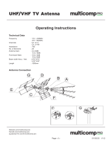
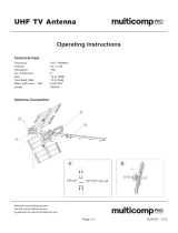
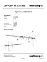
Page is loading ...

austriamicrosystems AG
is now
ams AG
The technical content of this austriamicrosystems application note is still valid.
Contact information:
Headquarters:
ams AG
Tobelbaderstrasse 30
8141 Unterpremstaetten, Austria
Tel: +43 (0) 3136 500 0
e-Mail: ams_sales@ams.com
Please visit our website at www.ams.com

AS1337 - Demo Board Manual
Step-Up Converter
www.austriamicrosystems.com Revision 1.00 1 - 4
Demo Board Manual
AS1337
200mA, DC-DC Step-Up Converter with Buck
Mode
www.austriamicrosystems.com/DC-DC_Step-Up/AS1337
ams AG
Technical content still valid

AS1337 - Demo Board Manual
Step-Up Converter
www.austriamicrosystems.com Revision 1.00 2 - 4
General Description
Board Description
Connector Description
Label Name Description Info
A
VIN
Supply Voltage
B
GND
Ground
Supply voltage ranging from 0.65V to 4.5V
C
EN
Enable Input
Set the digital input “high” for normal operation.
For shutdown, set “low”
D
VOUT
Output Voltage Output voltage ranging from 2.5V to 5.0V
E
POK
POK high, when VOUT is within regulation
Measurement Point Description
Label Name Description Info
F
VIN
Supply Voltage
G
GND
Ground
H
LX
External Inductor
I
VOUT
Output Voltage
J
EN
Enable Input
K
FB
Feedback
L
POK
POK
Measurement Points
M
EN
Enable
ON: The AS1337 is enabled
OFF: The AS1337 is disabled
No Jumper: Connect a valid enable signal
via external connector “C”.
Getting Started
The AS1337 Demoboard is designed to work with the AS1337A “Battery connected in shutdown” version.
With the resistor divider R1/R2 it is possible to adjust the VOUT.
On this Demoboard the following resistor values are mounted:
R1 = 560k and R2 = 330k VOUT
= 3.3V
Figure 1: Board Description
-
Connector
s
Figure 2
: Board Description
–
Measurement Points
A
C
B
E
D
B
F
G
G
M
J
K
H
I
L
ams AG
Technical content still valid

AS1337 - Demo Board Manual
Step-Up Converter
www.austriamicrosystems.com Revision 1.00 3 - 4
Bill of Materials
Layout of Demo Board
Board schematics and layout
Figure 3: Schematics
Figure 4: Top + Bottom Layer
Ref.
Function Value Description Manufacturer Mfg. Order Nr.
C1s Input Capacitor 10µF 0805 / X5R / 6.3V Murata GRM219R60J106KE19
C2s Output Capacitor 22µF 0805 / X5R / 6.3V Murata GRM21BR60J226ME39
L1 Coil 4.7µH 50mΩ / 1.82A / 6.8x6.0x2.4mm Coilcraft MOS6020-472ML
R1 Resistor (VOUT) 560k 0805/ ±1% Multicomp MC 0.1W 0805 1% 560K
R2 Resistor (VOUT) 330k 0805/ ±1% Multicomp MC 0.1W 0805 1% 330K
R3 R
POK
100k 0805/ ±1% Multicomp MC 0.1W 0805 1% 100K
U1 DC/DC Converter ASSE TQFN 3x3mm 8-pin Austriamicrosystems AG AS1337A-BTDT
ams AG
Technical content still valid

AS1337 - Demo Board Manual
Step-Up Converter
www.austriamicrosystems.com Revision 1.00 4 - 4
Copyright
Copyright © 1997-2010, austriamicrosystems AG, Tobelbaderstraße 30, 8141 Unterpremstätten - Graz, Austria -
Europe. Trademarks Registered ®. All rights reserved. The material herein may not be reproduced, adapted,
merged, translated, stored, or used without the prior written consent of the copyright owner.
All products and companies mentioned are trademarks or registered trademarks of their respective companies.
Disclaimer
Devices sold by austriamicrosystems AG are covered by the warranty and patent indemnification provisions
appearing in its Term of Sale. austriamicrosystems AG makes no warranty, express, statutory, implied, or by
description regarding the information set forth herein or regarding the freedom of the described devices from
patent infringement. Austriamicrosystems AG reserves the right to change specifications and prices at any time
and without notice. Therefore, prior to designing this product into a system, it is necessary to check with
austriamicrosystems AG for current information.
This product is intended for use in normal commercial applications. Applications requiring extended temperature
range, unusual environmental requirements, or high reliability applications, such as military, medical life-support
or life-sustaining equipment are specifically not recommended without additional processing by
austriamicrosystems AG for each application. For shipments of less than 100 parts the manufacturing flow might
show deviations from the standard production flow, such as test flow or test location.
The information furnished here by austriamicrosystems AG is believed to be correct and accurate. However,
austriamicrosystems AG shall not be liable to recipient or any third party for any damages, including but not
limited to personal injury, property damage, loss of profits, loss of use, interruption of business or indirect,
special, incidental or consequential damages, of any kind, in connection with or arising out of the furnishing,
performance or use of the technical data herein. No obligation or liability to recipient or any third party shall arise
or flow out of austriamicrosystems AG rendering of technical or other services.
Contact Information
Headquarters
austriamicrosystems AG
Tobelbaderstraße 30
A-8141 Unterpremstätten - Graz, Austria
T. +43 (0) 3136 500 0
F. +43 (0) 3136 5692
For Sales Offices, Distributors and Representatives, please visit:
http://www.austriamicrosystems.com/contact
ams AG
Technical content still valid
/


