
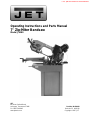
Operating Instructions and Parts Manual
7" Zip-Miter Bandsaw
Model J-9180
JET
427 New Sanford Road
LaVergne, Tennessee 37086 Part No. M-414464
Ph.: 800-274-6848 Revision C2 09/2018
www.jettools.com Copyright © 2017 JET
This .pdf document is bookmarked

2
Warranty and Service
JET
®
warrants every product it sells against manufacturers’ defects. If one of our tools needs service or repair, please
contact Technical Service by calling 1-800-274-6846, 8AM to 5PM CST, Monday through Friday.
Warranty Period
The general warranty lasts for the time period specified in the literature included with your product or on the official
JET branded website.
• JET products carry a limited warranty which varies in duration based upon the product. (See chart below)
• Accessories carry a limited warranty of one year from the date of receipt.
• Consumable items are defined as expendable parts or accessories expected to become inoperable within a
reasonable amount of use and are covered by a 90 day limited warranty against manufacturer’s defects.
Who is Covered
This warranty covers only the initial purchaser of the product from the date of delivery.
What is Covered
This warranty covers any defects in workmanship or materials subject to the limitations stated below. This warranty
does not cover failures due directly or indirectly to misuse, abuse, negligence or accidents, normal wear-and-tear,
improper repair, alterations or lack of maintenance. JET woodworking machinery is designed to be used with Wood.
Use of these machines in the processing of metal, plastics, or other materials outside recommended guidelines may
void the warranty. The exceptions are acrylics and other natural items that are made specifically for wood turning.
Warranty Limitations
Woodworking products with a Five Year Warranty that are used for commercial or industrial purposes default to a
Two Year Warranty. Please contact Technical Service at 1-800-274-6846 for further clarification.
How to Get Technical Support
Please contact Technical Service by calling 1-800-274-6846. Please note that you will be asked to provide proof
of initial purchase when calling. If a product requires further inspection, the Technical Service representative will
explain and assist with any additional action needed. JET has Authorized Service Centers located throughout the
United States. For the name of an Authorized Service Center in your area call 1-800-274-6846 or use the Service
Center Locator on the JET website.
More Information
JET is constantly adding new products. For complete, up-to-date product information, check with your local distributor
or visit the JET website.
How State Law Applies
This warranty gives you specific legal rights, subject to applicable state law.
Limitations on This Warranty
JET LIMITS ALL IMPLIED WARRANTIES TO THE PERIOD OF THE LIMITED WARRANTY FOR EACH PRODUCT.
EXCEPT AS STATED HEREIN, ANY IMPLIED WARRANTIES OF MERCHANTABILITY AND FITNESS FOR A
PARTICULAR PURPOSE ARE EXCLUDED. SOME STATES DO NOT ALLOW LIMITATIONS ON HOW LONG AN
IMPLIED WARRANTY LASTS, SO THE ABOVE LIMITATION MAY NOT APPLY TO YOU.
JET SHALL IN NO EVENT BE LIABLE FOR DEATH, INJURIES TO PERSONS OR PROPERTY, OR FOR
INCIDENTAL, CONTINGENT, SPECIAL, OR CONSEQUENTIAL DAMAGES ARISING FROM THE USE OF OUR
PRODUCTS. SOME STATES DO NOT ALLOW THE EXCLUSION OR LIMITATION OF INCIDENTAL OR
CONSEQUENTIAL DAMAGES, SO THE ABOVE LIMITATION OR EXCLUSION MAY NOT APPLY TO YOU.
JET sells through distributors only. The specifications listed in JET printed materials and on official JET website are
given as general information and are not binding. JET reserves the right to effect at any time, without prior notice,
those alterations to parts, fittings, and accessory equipment which they may deem necessary for any reason
whatsoever. JET
®
branded products are not sold in Canada by JPW Industries, Inc.
Product Listing with Warranty Period
90 Days – Parts; Consumable items
1 Year – Motors; Machine Accessories
2 Year – Metalworking Machinery; Electric Hoists, Electric Hoist Accessories; Woodworking Machinery used
for industrial or commercial purposes
5 Year – Woodworking Machinery
Limited Lifetime – JET Parallel clamps; VOLT Series Electric Hoists; Manual Hoists; Manual Hoist
Accessories; Shop Tools; Warehouse & Dock products; Hand Tools; Air Tools
NOTE: JET is a division of JPW Industries, Inc. References in this document to JET also apply to JPW Industries,
Inc., or any of its successors in interest to the JET brand.

3
Table of Contents
Warranty and Service .................................................................................................................................... 2
Table of Contents .......................................................................................................................................... 3
IMPORTANT SAFETY INSTRUCTIONS ...................................................................................................... 4
Introduction.................................................................................................................................................... 6
Specifications ................................................................................................................................................ 6
Shipping Contents ......................................................................................................................................... 7
Contents of the Carton .............................................................................................................................. 7
Hardware ................................................................................................................................................... 7
Machine Features ......................................................................................................................................... 7
Machine Base ............................................................................................................................................ 7
Saw Head .................................................................................................................................................. 7
Work Stop .................................................................................................................................................. 7
Control Panel ............................................................................................................................................. 7
Assem bly ....................................................................................................................................................... 8
Stand Assembly ......................................................................................................................................... 8
Mounting Saw to Stand ............................................................................................................................. 8
Electrical Connection .................................................................................................................................... 8
Controls and Indicators ................................................................................................................................. 9
Control Panel ............................................................................................................................................. 9
Feed Rate Control ..................................................................................................................................... 9
Blade Tension Indicat or ............................................................................................................................. 9
Blade Speeds ............................................................................................................................................ 9
Blade Selection ........................................................................................................................................... 10
Blade Break-in Procedures ..................................................................................................................... 10
Operations ................................................................................................................................................... 10
Hydraulic Feed Control ............................................................................................................................ 10
Evaluating Cutting Efficiency ................................................................................................................... 10
Setting the Work Stop.............................................................................................................................. 11
Quick Release Vise Operation ................................................................................................................ 11
Miter Cuts ................................................................................................................................................ 12
Coolant Flow Control ............................................................................................................................... 12
Adjustments ................................................................................................................................................ 12
Blade Guide Adjustm ent .......................................................................................................................... 12
Guide Bearing Adjustment ...................................................................................................................... 13
Blade Tension .......................................................................................................................................... 14
Limit Switch Adjustment .......................................................................................................................... 14
Maintenance ................................................................................................................................................ 15
Changing Blades ..................................................................................................................................... 15
Cleaning ...................................................................................................................................................... 16
Lubrication ................................................................................................................................................... 16
Coolant ........................................................................................................................................................ 16
Troubleshooting .......................................................................................................................................... 17
Parts ............................................................................................................................................................ 18
Replacement Parts .................................................................................................................................. 18
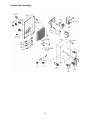
Saw Assembly – Parts............................................................................................................................. 19
Saw Assembly Drawing (1 of 3) .............................................................................................................. 23
Saw Assembly Drawing (2 of 3) .............................................................................................................. 24
Saw Assembly Drawing (3 of 3) .............................................................................................................. 25
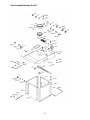
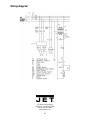
Electrical Box Assembly – Parts .............................................................................................................. 26
Electrical Box Assembly .......................................................................................................................... 27
Wiring Diagram ........................................................................................................................................... 28

4
IMPORTANT SAFETY INSTRUCTIONS
WARNING – To reduce risk of injury:
1. Read and understand the entire owner's manual before attempting assembly or operation.
2. Read and understand the warnings posted on the machine and in this manual. Failure to comply with
all of these warnings may cause serious injury.
3. Replace the warning labels if they become obscured or removed.
4. This band saw is designed and intended for use by properly trained and experienced personnel only.
If you are not familiar with the proper and safe operation of a band saw, do not use until proper
training and knowledge have been obtained.
5. Do not use this band saw for other than its intended use. If used for other purposes, JET, disclaims
any real or implied warranty and holds itself harmless from any injury that may result from that use.
6. Always wear approved safety glasses/face shields while using this band saw. Everyday eyeglasses
only have impact resistant lenses; they are not safety glasses.
7. Before operating this band saw, remove tie, rings, watches and other jewelry, and roll sleeves up past
the elbows. Remove all loose clothing and confine long hair. Non-slip footwear or anti-skid floor strips
are recommended. Do not wear gloves.
8. Wear ear protectors (plugs or muffs) during extended periods of operation.
9. Do not operate this machine while tired or under the influence of drugs, alcohol or any medication.
10. Make certain the switch is in the OFF position before connecting the machine to the power supply.
11. Make certain the machine is properly grounded.
12. Make all machine adjustments or maintenance with the machine unplugged from the power source.
13. Remove adjusting keys and wrenches. Form a habit of checking to see that keys and adjusting
wrenches are removed from the machine before turning it on.
14. Keep safety guards in place at all times when the machine is in use. If removed for maintenance
purposes, use extreme caution and replace the guards immediately.
15. Check damaged parts. Before further use of the machine, a guard or other part that is damaged
should be carefully checked to determine that it will operate properly and perform its intended
function. Check for alignment of moving parts, binding of moving parts, breakage of parts, mounting
and any other conditions that may affect its operation. A guard or other part that is damaged should
be properly repaired or replaced.
16. Provide for adequate space surrounding work area and non-glare, overhead lighting.
17. Keep the floor around the machine clean and free of scrap material, oil and grease.
18. Keep visitors a safe distance from the work area. Keep children away.
19. Make your workshop child proof with padlocks, master switches or by removing starter keys.
20. Give your work undivided attention. Looking around, carrying on a conversation and “horse-play” are
careless acts that can result in serious injury.
21. Maintain a balanced stance at all times so that you do not fall or lean against the blade or other
moving parts. Do not overreach or use excessive force to perform any machine operation.
22. Use the right tool at the correct speed and feed rate. Do not force a tool or attachment to do a job for
which it was not designed. The right tool will do the job better and safer.
23. Use recommended accessories; improper accessories may be hazardous.

5
24. Maintain tools with care. Keep blades sharp and clean for the best and safest performance. Follow
instructions for lubricating and changing accessories.
25. Make sure the work piece is securely clamped in the vise. Never use your hand to hold the work
piece.
26. Turn off the machine before cleaning. Use a brush or compressed air to remove chips or debris — do
not use your hands.
27. Do not stand on the machine. Serious injury could occur if the machine tips over.
28. Never leave the machine running unattended. Turn the power off and do not leave the machine until
the blade comes to a complete stop.
29. Remove loose items and unnecessary work pieces from the area before starting the machine.
Familiarize yourself with the following safety notices used in this manual:
This means that if precautions are not heeded, it may result in minor injury and/or
possible machine damage.
This means that if precautions are not heeded, it may result in serious injury or possibly
even death.
- - SAVE THESE INSTRUCTIONS - -
WARNING: Some dust, fumes and gases created by power sanding, sawing, grinding, drilling,
welding and other construction activities contain chemicals known to the State of California to cause
cancer and birth defects or other reproductive harm. Some examples of these chemicals are:
• lead from lead based paint
• crystalline silica from bricks, cement and other masonry products
• arsenic and chromium from chemically treated lumber
Your risk of exposure varies, depending on how often you do this type of work. To reduce your
exposure to these chemicals, work in a well-ventilated area and work with approved safety equipment,
such as dust masks that are specifically designed to filter out microscopic particles. For more
information
g
o to htt
p
://www.
p
65warnin
g
s.ca.
g
ov
/
and htt
p
://www.
p
65warnin
g
s.ca.
g
ov/wood.
WARNING: This product can expose you to chemicals including lead which is known to the State
of California to cause cancer and birth defects or other reproductive harm, and ethylbenzene which is
known to the State of California to cause cancer. For more information go to
http://www.p65warnings.ca.gov.

6
Introduction
This manual is provided by JET, covering the safe operation and maintenance procedures for a JET
Model J-9180 zip-miter bandsaw. This manual contains instructions on installation, safety precautions,
general operating procedures, maintenance instructions and parts breakdown. This machine has been
designed and constructed to provide consistent, long-term operation if used in accordance with
instructions set forth in this manual. If there are any questions or comments, please contact either your
local supplier or JET. JET can also be reached at our web site: www.jettools.com.
The JET Model J-9180 bandsaw is designed for medium production cut-off work. Two cutting speeds and
a hydraulic feed control allow the efficient cutting of virtually any material.
The Model J-9180 bandsaw is equipped with a coolant system which can greatly extend blade life and
speed the cutting of a variety of materials which are best cut with cutting fluids and coolants.
Register your product using the mail-in card provided, or register online:
http://www.jettools.com/us/en/service-and-support/product-registration/
Specifications
Model .................................................................................................................................................... J-9180
Stock Number ..................................................................................................................................... 414464
Cutting Capacity
Round at 90° (in.) ..................................................................................................................................... 7
Round at 45° (in.) ............................................................................................................................... 4-1/2
Round at 60° (in.) ............................................................................................................................... 2-3/4
Rectangle at 90° (in.) ................................................................................................................... 7-7/8 x 6
Rectangle at 45° (in.) ........................................................................................................... 4-7/8 x 4-5/16
Rectangle at 60° (in.) ............................................................................................................. 2-3/4 x 2-3/4
Blade Provided (in.) ............................................................................................... 3/4” x0 .035 x 82” x 5/8VT
Blade Speeds (SFPM) ....................................................................................................................... 157,314
Blade Wheel Diameter (in.) ................................................................................................................... 10-1/2
Coolant Capacity (qt.) ................................................................................................................................. 10
Bed Height (in.) ..................................................................................................................................... 35-7/8
Motor ..................................................................................................................................... 1HP, 230V, 3Ph
Floor Space Required (L x W x H)(in.) .................................................................................. 44 x 22 x 29-1/2
Net Weight (lbs.) ....................................................................................................................................... 375
The above specifications were current at the time this manual was published, but because of our policy of
continuous improvement, JET reserves the right to change specifications at any time and without prior
notice, without incurring obligations.

7
Shipping Contents
Contents of the Carton
1 Band Saw (not shown)
1 Front Stand Panel (A)
1 Rear Stand Panel (B)
1 Left Stand Panel (C)
1 Right Stand Panel (D)
1 Bottom Plate (E)
1 Operating Instructions/Parts List
1 Warranty Card
Contents of the Carton
Hardware
04 M8 x 25 Socket Head Cap Screw (F)
12 M8 x 20 Hex Cap Screw (G)
28 M8 Flat Washer (H)
24 M8 Hex Nut (J)
Hardware (Actual Size)
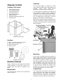
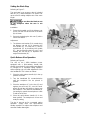
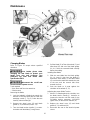
Machine Features
Figures 1 depicts the main features of the Model
J-9180 Bandsaw. The machine consists of a
machine base onto which is installed a saw
head.
Machine Base
The machine base consists of four panels that
require assembly.
Saw Head
The saw head (Figure 1) consists of a drive
motor, gearbox, blade wheels, blade guides and
supports, control panel, blade tension
mechanism, wire brush, and the saw blade.
The drive wheel is installed on the output shaft
of the gearbox. The driven wheel is located on
the left side of the machine and is mounted on a
shaft that is part of the blade tension mechan-
ism. The blade tension mechanism is used to
tighten the saw blade on the blade wheels.
Blade tension generally requires adjustment only
after the saw blade is changed, but the tension
should be monitored with the convenient blade
tension indicator.
Figure 1
Work Stop
A work stop is provided with the machine to
allow cutting multiple pieces of identical length
(refer to Figure 5). The stop consists of a set rod
onto which is installed a distance set bracket,
stop rod assembly and two lock handles. The
rod is installed in a bore in the front of the saw
bed. The distance set bracket is moved in or out
on the set rod to establish the length of the
workpiece and the stop rod can be adjusted to
accommodate workpieces of various widths.
Control Panel
The control panel is mounted on the top of the
saw head. Refer to the Controls and Indicators
section (page 9) for a description of the controls.
Switches and fuses required for operation and
protection of the drive motor are inside the box.

8
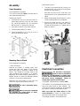
Assembly
Stand Assembly
Tools required for assembly:
Two 1/2-inch wrenches (Note: A ratchet wrench
may speed assembly time.)
Referring to Figure 2:
1. Assemble the rear (D
1
) and right side (E
1
)
panels with three M8 x 20 hex cap screws
(A), six M8 flat washers (B
1
, B
2
) and three
M8 hex nuts (C). Tighten the hex nuts.
2. Assemble E
2
and D
2
in the same manner.
3. Position bottom plate (F) in stand.
4. Finish assembling E
2
to D
1
and E
1
to D
2
in
the same manner as above.
Figure 2
Mounting Saw to Stand
Tools required for assembly:
– 8mm hex wrench
Remove any plastic or holding straps from
around the band saw. Areas of the machine
have been given a protective coating at the
factory. This should be removed using a soft
cloth moistened with kerosene or a cleaner-
degreaser. Do not use gasoline, paint thinner, or
lacquer thinner as these will damage painted
surfaces. Do not use an abrasive pad.
Determine the final location for the saw and
allow for a sufficient work space around it.
The saw is extremely heavy.
Use a hoist to lift.
When moving the saw/stand
top assembly the cutting head, or “bow”,
should be in the down position.
Referring to Figure 3:
1. The saw (A) and stand top (B) come as an
assembled unit. Use a hoist to lift and place
the saw onto the stand (C).
Note that the front of the saw faces the
same direction as the indented panel of the
stand.
2. Adjust the stand top (B) and stand (C) so the
corner mounting holes (D) are aligned.
3. Secure the stand top (B) to the stand (C)
with four each M8 hex socket head screws
(E) with M8 flat washers (F). Tighten with an
8mm hex wrench.
Figure 3
Electrical Connection
All electrical connections
must be done by a qualified
electrician. All adjustments or repairs must
be done with the machine disconnected from
the power source, unplugged. Failure to
comply may result in serious injury!
The Model J-9180 bandsaw is rated at 230V.
This machine is not supplied with a plug. Use a
plug and outlet rated at least 20amps. The
circuit for the machine should also be protected
by at least a 20 amp circuit breaker or fuse.
Make sure that the blade moves in the
correct direction. If it does not, simply reverse
two of the phase wires on the supply input.
The sawing machine is now ready for use.

9
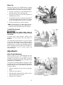
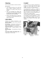
Controls and Indicators
Control Panel
The operating controls for the bandsaw are
located on the control panel (Figure 4) and
consist of the following controls and indicators:
Emergency Stop Switch – by depressing this
switch the user can quickly stop the machine
when it is in operation; to restart, turn clockwise
slightly to release then press Start switch
Feed Rate Control – used in conjunction with the
Feed Rate Start/Stop Control (see below); this
knob is used to set the downward head speed
that is applied to the saw blade. The feed rate is
proportional to the opening of the valve. When
set to zero, the saw head is locked in position.
Increasing the valve opening (counter-clockwise
adjustment) increases the feed rate; decreasing
the valve opening (clockwise adjustment)
reduces the feed rate.
Motor Speed Selector – select Low for 137
SFPM, High for 275 SFPM; machine will not
operate when Off is selected.
On/Off Switch – main power switch
Standby Lamp Indicator – indicates that power is
present, i.e., machine is plugged in and On/Off
Switch in set to ON.
Start Switch – press to start machine, also: set
On/Off Switch to ON, select Motor Speed
Selector to Low or High, Emergency Stop must
be released.
Feed Rate Control
The Feed Rate Controls (Figure 5) are mounted
on the hydraulic cylinder located below the
control panel.
With the Feed Rate Start/Stop (F) lever in the
locked position the saw head is prevented from
descending; in the unlocked position the saw
head will descend at the rate determined by the
Feed Rate Control (G) setting.
Blade Tension Indicator
The Blade Tension Indicator is located on the
saw head (see Figure 1) – indicates the blade
tension. To set blade tension refer to the
Changing Blades section on page 15.
Blade Speeds
See Motor Speed Selector above.
Figure 4
Figure 5
Figure 6

10
Blade Selection
The cut-off saw is delivered with a saw blade
that is adequate for a variety of cut-off jobs on a
variety of common materials. A general-purpose
blade is provided as standard equipment with
the machine. After-market blades can be
acquired for specific cutting jobs.
A coarse blade could be used for a solid steel
bar, but a finer tooth blade would be used on a
thin-wall steel tube. In general, the blade choice
is determined by the thickness of the material;
the thinner the materials; the finer the tooth
pitch.
A minimum of three teeth should be on the
workpiece at all times for proper cutting. The
blade and workpiece can be damaged if the
teeth are so far apart that they straddle the
workpiece.
For very high production on cutting of special
materials, or to cut hard-to-cut materials such as
stainless steel, tool steel, or titanium, call JET,
for more specific blade recommendations. JET
can provide you with very specific instructions
regarding the best blade (and coolant or cutting
fluid, if needed) for the material or shape
supplied.
Blade Break-in Procedures
New blades are very sharp and, therefore, have
a tooth geometry that is easily damaged if a
careful break-in procedure is not followed.
Consult the blade manufacturer’s literature for
break-in of specific blades on specific materials.
However, the following procedure will be
adequate for break-in of JET-supplied blades on
lower alloy ferrous materials.
1. Clamp a section of round stock in the vise.
The stock should be 2 inches or larger in
diameter.
2. Operate the saw at low speed. Start the cut
with a very light feed rate.
3. When the saw has completed 1/3 of the cut,
increase the feed rate slightly and allow the
saw to complete the cut.
4. Keep the hydraulic cylinder needle valve in
the same position and begin a second cut
on the same or similar workpiece.
5. When the blade has completed about 1/3 of
the cut, increase the feed rate.
Watch the chip formation until cutting is at its
most efficient rate and allow the saw to
complete the cut (refer to Evaluating Blade
Efficiency below). The blade is now consid-
ered ready for use.
Operations
Hydraulic Feed Control
The weight of the saw head provides the force
needed to cut through the workpiece. The cut-off
saw has a hydraulic cylinder that controls the
feed rate of the saw.
The hydraulic feed control circuit consists of a
single acting hydraulic cylinder and a feed rate
control. The feed control cylinder resists motion
in the downward direction to control the feed
rate. The control cylinder offers no resistance
when raised upward.
The feed rate adjustment (G, Fig. 4) controls the
rate at which the saw head is lowered. The
control knob (needle valve) controls the rate at
which the hydraulic fluid is released from the
hydraulic cylinder. When the needle valve is
closed, the cylinder is locked. With the needle
valve slightly open, the cylinder permits slow, or
light, downward force. Opening the needle valve
further increases the feed rate.
The needle valve is adjusted until the saw is
operating efficiently. The efficiency of operation
is usually evaluated by observing chip formation.
Blade efficiency is further described below.
A lever (F, Fig. 5) is used to permit or stop the
saw head from descending regardless of the
feed rate adjustment (G, Fig. 5) setting.
Evaluating Cutting Efficiency
Is the blade cutting efficiently? The best way to
determine this is to observe the chips formed by
the cutting blade.
If the chip formation is powdery, then the feed is
much too light or the blade is dull.
If the chips formed are curled, but colored – blue
or straw colored from heat generated during the
cut – then the feed rate is too high.
If the chips are slightly curled and are not
colored by heat – the blade is sufficiently sharp
and is cutting at its most efficient rate.

11
Setting the Work Stop
Referring to Figure 7:
The work stop is an accessory that is included
with the JET J-9180 Bandsaw. It is used to set
up the saw for making multiple cuts of the same
length.
Do not allow the blade to rest
on the workpiece when the saw is not
cutting.
Installation
1. Screw the threaded end of the distance set
rod (A) into the hole at the front of the base
(B) as shown.
2. Secure by tightening the lock nut (C) with a
22mm hex wrench.
Adjustment
3. The distance set bracket (D) is moved along
the distance set rod (A) by loosening the
lock handle (H). The stop rod (F) can be
repositioned (G) by loosening lock handle
(E) – also by loosening the lock nut (C) and
rotating the set rod (A) to reposition the
angle of the bracket (D).
Quick Release Vise Operation
Referring to Figure 8:
The vise on the J-9180 bandsaw comes
equipped with a quick-release handle that
permits the workpiece to be rapidly repositioned
or changed for a repeated cutting operation
while requiring only one initial adjustment of the
vise handwheel. This is done as follows:
1. Place the quick-release handle (A) in the up
position as shown.
2. Turn the handwheel (B) counterclockwise
until the workpiece can be placed in
position.
3. Place the workpiece (C) in the vise (D) and
against the work stop (E); turn the hand-
wheel (B) until the vise begins to clamp onto
the workpiece. Then back the handwheel off
just enough to permit the workpiece to slide
in and out of the vise.
4. Place the quick-release handle (A) in the
down position. The workpiece is secure and
ready for cutting.
The vise is now set up for a repeated cutting
operation. Simply raise the quick-release
handle, reposition or replace the workpiece and
reset the handle down again.
Figure 7
Figure 8

12
Miter Cuts
Referring to Figure 9, the J-9180 bandsaw is capable
of making angle cuts from 0–60º. The vise remains
stationary while the saw head is adjusted as follows:
1. Place the saw head (F) in the raised position so
the blade doesn't catch in the table slots.
2. Set the lock handle (A) to the unlock position as
indicated by the arrows.
3. Using handles (B and C), rotate the saw head (F)
to any desired angle within a range of 0º (square
cut) to 60º, setting it to the scale (D) on the base.
4. Set the lock handle (A) to the lock position.
Note: Two miter stops (E) on either side of the saw
base set the miter range of 0–60º. Adjust only if
necessary so the saw travel stops at 0º and 60º.
Coolant Flow Control
The coolant pump must be
submerged before operating to prevent damage
to the pump.
A coolant pump, which provides coolant to the
workpiece, runs at all times when the machine is
turned on.
Two coolant flow control valves (A, Fig. 10), located
on the top of the bearing blocks, control the amount
of flow from the nozzles. Coolant flow should be
adjusted to be no more than the saw blade can draw
into the workpiece by the movement of the blade. To
stop coolant flow, turn the control valves fully
counterclockwise.
Adjustments
Blade Guide Adjustment
Refer to Figure 11. The J-9180 Bandsaw has two
blade guide assemblies; one is stationary (A) and
mounted to the body of the saw head. The other,
consisting of a blade guide support or bracket (B) and
blade guide (C), is adjustable.
The position of the blade guides is important in order
to make accurate cuts and prolong blade life and is
determined by the size of the workpiece. Adjustment
is made as follows:
1. Place the workpiece (D) in the vise (E) and clamp
tightly.
2. Loosen the lock handle (F).
3. Slide the guide support (B) left or right so that it
just clears the piece to be cut (D).
4. Tighten the lock handle (F).
Figure 9
Figure 10
Figure 11

13
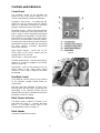
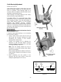
Guide Bearing Adjustment
Referring to Figure 12:
Guide bearings are located on either side of the saw
blade and provide stability for the blade when the
saw is in operation. These bearings rotate on an
eccentric shaft so the distance from the blade can be
adjusted for optimal performance.
Guide bearings are initially adjusted at the factory
and should rarely require adjustment.
It is always better to try a new blade when cutting
performance is poor. If performance remains poor
after changing the blade, check the blade guides for
proper guide bearing spacing. For most efficient
operation and maximum accuracy, clearance
between the blade and the guide bearings should be
0.001-inch. The bearings will still turn freely with this
clearance. If the clearance is incorrect, the blade may
track off the drive wheel.
Disconnect the bandsaw from its
electrical power source.
If required, adjust guide bearings on one assembly
then the other as follows:
1. Using a 14mm wrench loosen two lock nuts (A)
that secure the eccentric bushings (B) while
maintaining the positions of the eccentric
bushings with a 6mm wrench.
2. Position the bearings (B) by adjusting the
bushings (C) with the 6mm wrench. Set the
clearance between the bearings (B) and blade
(D) at approximately 0.001 inch.
Note: Only the bearing towards the front is
mounted on an eccentric bushing. Make adjust-
ments on this bearing.
When properly adjusted, the blade should be in a
vertical position between the bearings as shown
in Figure 13.
3. While maintaining the new position of the
bushings with the 6mm wrench, secure the
settings by tightening the lock nuts (A).
Figure 12
Figure 13
Outer
Rolle
r
Inner
Roller
INCORRECT CORRECT
Saw Blade
Saw Blade

14
Blade Tension
Blade tension is covered in the Changing Blades
section on page 15.
Limit Switch Adjustment
Refer to Figure 14.
The J-9180 bandsaw should shut off automatically
when a cut is completed. If not, the limit switch (A)
located below the control panel (Figure 1) probably
needs to be adjusted as follows:
Disconnect the cut-off saw from
its electrical power source.
1. Place the saw in the lowered position to repres-
ent the completion of a cutting operation.
The microswitch wheel (E) should be pressed
against the plate (F) which is attached to the
hydraulic cylinder bracket (G). If this is not the
case, make a note of how much the switch
assembly (A) should be repositioned upwards.
2. Using a crosspoint screwdriver, remove two
screws (C) and the switch (A) from its mounting
plate (B).
3. With a 3mm hex wrench, loosen two screws (D)
and reposition the mounting plate (B) as
determined in step 1.
4. Tighten the mounting plate screws (D) and
reinstall the switch assembly (A).
5. Test to verify that the bandsaw shuts off when a
cut is completed. If it does not, repeat above
steps.
Figure 14

15
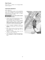
Maintenance
Figure 15
Changing Blades
Refer to Figure 15 except where specified
otherwise.
Use leather gloves when
changing the saw blade to protect your
hands from cuts and scratches. Use
protective eye wear that meets ANSI
Specification Z87.1
Disconnect the cut-off saw
from its electrical power source.
Tools required:
-- 3mm, 4mm and 5mm hex wrenches
-- 12mm wrench
Removing the Blade
1. Lock the hydraulic cylinder that controls the
descent of the saw head with the feed rate
start/stop control (F, Fig. 5). Raise the saw
head (A) about half way up.
2. Remove the wheel cover (B) and blade
guards (C, D) and brush (Inset 2 - M).
3. Turn the blade tension handle (J) counter-
clockwise until the blade (E) hangs loose.
4. Pull the blade (E) off the drive wheel (F) and
idler wheel (G) and out of the blade guides
(H
1
, H
2
). Store the removed blade carefully
before proceeding.
Installing New Blade
5. Slide the new blade into the blade guides
(H
1
, H
2
, Inset 1), then loop the blade (E)
around the drive wheel (F) and idler wheel
(G) such that the teeth face towards the rear
of the saw and the smooth side faces
towards the front.
6. Push the blade so it seats against the
shoulders of the wheels (F, G).
Adjusting the proper Blade Tension
7. When it is seated against the shoulder, turn
the blade tension handle (J) clockwise to
increase the tension until the scale for the
3/4" blade tension measures 14–21KPSI
(green zone) on the tension indicator (K).
8. Replace the wheel cover (B) and blade
guards (C, D) and brush (M).
9. Reconnect the saw to the electrical power
source.

16
Cleaning
Clean off any preservative on machine surfaces.
After cleaning:
1. Coat machined surfaces of the cutoff saw
with a medium consistency machine oil.
Reapply the oil coating at least every six
months.
2. Clean up accumulated saw cuttings after
use. Make sure the lead screw and rapid nut
are kept free from saw cuttings and other
material that would cause damage.
3. Clean the chip sludge from the coolant tank.
The frequency should be determined by how
often the saw is used.
Lubrication
Lubricate the following components at the
specified frequencies and using the lubricants
defined as follows:
Ball Bearings – the bearings are lubricated and
sealed – periodic lubrication is not required.
Blade Guide Bearing – the bearings are lubri-
cated and sealed – periodic lubrication is not
required.
Wheel Bushings – six to eight drops of oil each
week.
Pivot Points, Shafts, and Bearing areas – six
to eight drops of oil each week.
Coolant
Change coolant with a frequency appropriate to
the type of coolant being used. Oil based
coolants can sour. Refer to the coolant
supplier’s instructions for change frequency.
The general-purpose coolant is a mixture of
water-soluble oil or synthetic based coolant and
water. Mix one part of coolant to ten parts of
water (one quart of oil to ten quarts water). Ten
quarts of coolant is the amount required for the
coolant pump to operate properly.
There are numerous coolants on the market that
are formulated for special applications. Consult
your local distributor for details in the event you
have a long range production task, or are
required to cut some of the more exotic
materials.
Figure 16

17
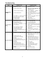
Troubleshooting
Fault Probable Cause Suggested remedy
Excessive blade
breakage
1. Material loose in vise.
2. Incorrect speed or feed.
3. Teeth too coarse for material.
4. Incorrect blade tension.
5. Saw blade is in contact with work-
piece before the saw is started.
6. Misaligned guides.
7. Cracking at weld.
1. Clamp work securely.
2. Check Machinist’s Handbook for
speed/feed appropriate for the
material being cut.
3. Check Machinist’s Handbook for
recommended blade type.
4. Adjust blade tension to the point
where the blade just does not slip on
the wheel.
5. Start the motor before placing the
saw on the workpiece.
6. Adjust guides.
7. Longer annealing cycle.
Premature blade
dulling
1. Blade teeth too coarse.
2. Blade speed too high.
3. Inadequate feed pressure.
4. Hard spots in workpiece or scale
on/in workpiece.
5. Work hardening of material
(especially stainless steel).
6. Insufficient blade tension.
7. Operating saw without pressure on
workpiece.
1. Use a finer tooth blade.
2. Try a lower blade speed.
3. Decrease spring tension.
4. Increase feed pressure (hard spots).
Reduce speed, increase feed pres-
sure (Scale).
5. Increase feed pressure by reducing
spring tension.
6. Increase tension to proper level.
7. Do not run blade at idle in/on
material.
Bad cuts (crooked)
1. Workpiece not square with blade.
2. Feed pressure too fast.
3. Guide bearings not adjusted
properly.
4. Inadequate blade tension.
5. Span between the two blade guides
too wide.
6. Dull blade.
7. Incorrect blade speed.
8. Blade guide assembly is loose.
9. Blade guide bearing assembly loose.
10. Blade track too far away from wheel
flanges.
11. Guide bearing worn.
1. Adjust vise so it is square with the
blade. (Always clamp the workpiece
tightly in the vise.)
2. Decrease pressure.
3. Adjust guide bearing clearance to
0.001 inch (0.002 inch maximum).
4. Gradually increase blade tension.
5. Move blade guide bracket closer to
work.
6. Replace blade.
7. Check blade speed.
8. Tighten blade guide assembly.
9. Tighten blade guide bearing
assembly.
10. Adjust blade tracking.
11. Replace worn bearing.

18
Troubleshooting
Fault Probable Cause Suggested remedy
Bad cuts (rough)
1. Blade speed too high for feed
pressure.
2. Blade is too coarse.
1. Reduce blade speed and feed
pressure.
2. Replace with finer blade.
Blade is twisting
1. Blade is binding in the cut.
2. Blade tension too high
1. Decrease feed pressure.
2. Decrease tension on Blade
Unusual wear on
side/back of blade
1. Blade guides worn
2. Blade guide bearings not adjusted.
3. Blade guide bearing bracket is
loose.
1. Replace blade guides.
2. Adjust blade guide bearings.
3. Tighten blade guide bearing bracket.
Parts
Replacement Parts
Replacement parts are listed on the following pages. To order parts or reach our service department, call
1-800-274-6848 Monday through Friday, 8:00 a.m. to 5:00 p.m. CST. Having the Model Number and
Serial Number of your machine available when you call will allow us to serve you quickly and accurately.
Non-proprietary parts, such as fasteners, can be found at local hardware stores, or may be ordered from
JET. Some parts are shown for reference only, and may not be available individually.

19
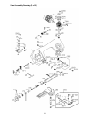
Saw Assembly – Parts
Index No. Part No. Description Size Qty
1 ............... J-9180-01G .............. Body Frame.......................................................... .................................... 1
2 ............... J-9180-02G .............. Anchor Block ........................................................ .................................... 1
2A ............. 9180-02A ................. Anchor Plate......................................................... .................................... 1
2B ............. TS-2245102 ............. Button Head Socket Screw .................................. M5x10 ......................... 2
3 ............... 9180-03 .................... Shaft ..................................................................... .................................... 1
4 ............... TS-1504041 ............. Socket Head Cap Screw ...................................... M8x20 ......................... 1
5 ............... 9180-05 .................... Bearing Cover ...................................................... .................................... 2
6 ............... 9180-06 .................... Tapered Bearing .................................................. .................................... 2
7 ............... 9180-07 .................... Washer ................................................................. .................................... 1
10-1 .......... 9180-10-1 ................. Blade Tension Gauge .......................................... .................................... 1
11 ............. 9180-11 .................... Bearing ................................................................. .................................... 1
12 ............. 9180-12 .................... Handle .................................................................. .................................... 2
13 ............. 9180-13 .................... Hub ....................................................................... .................................... 1
14 ............. 9180-14 .................... Spring Washer ..................................................... øID16.3xø31.5x1.8t .. 10
15 ............. 9180-15 .................... Lead Screw .......................................................... .................................... 1
16 ............. TS-154010 ............... Hex Nut ................................................................ M16 ............................. 1
17 ............. TS-1504051 ............. Socket Head Cap Screw ...................................... M8x25 ......................... 3
18 ............. 9180-18G ................. Fixed Block........................................................... .................................... 1
19 ............. 9180-19 .................... Pin ........................................................................ ø 5x40 ......................... 2
20 ............. TS-1503051 ............. Socket Head Cap Screw ...................................... M6x20 ......................... 2
21 ............. 9180-21 .................... Fixed Block........................................................... .................................... 1
22 ............. TS-2248252 ............. Button Head Socket Screw .................................. M8x25 ......................... 2
23 ............. TS-1523051 ............. Set Screw ............................................................. M6x16 ......................... 2
23-1 .......... TS-1523061 ............. Set Screw ............................................................. M6x20 ......................... 6
24 ............. 9180-24 .................... Locking Handle .................................................... M8x30 ......................... 1
25 ............. 9180-25 .................... Blade Adjust Bar .................................................. .................................... 1
26 ............. TS-1524021 ............. Set Screw ............................................................. M8x10 ......................... 2
27 ............. TS-1503021 ............. Socket Head Cap Screw ...................................... M6x10 ......................... 1
28 ............. 9180-28 .................... Lift Handle ............................................................ .................................... 1
29 ............. 9180-29 .................... Handle Grip .......................................................... .................................... 1
30 ............. 9180-30 .................... Fixed Plate ........................................................... .................................... 1
36-1 .......... TS-1505081 ............. Socket Head Cap Screw ...................................... M10x60 ....................... 1
37 ............. 9180-37 .................... Bearing Shaft ....................................................... .................................... 2
38 ............. 9180-38 .................... Guide Block (Front) .............................................. .................................... 1
39-1 .......... TS-1551071 ............. Lock Washer ........................................................ M10 ............................. 1
40 ............. 9180-40 .................... Hose Clip .............................................................. ø8 ................................ 3
41 ............. TS-1504031 ............. Socket Head Cap Screw ...................................... M8x16 ......................... 3
43 ............. 9180-43 .................... Eccentric Guide .................................................... .................................... 2
44 ............. BB-608ZZ ................. Bearing ................................................................. 608ZZ........................ 10
45 ............. 9180-45 .................... C-Retainer Ring ................................................... ø8 ................................ 4
46 ............. 9180-46 .................... Eccentric Guide .................................................... .................................... 2
47 ............. TS-2245122 ............. Button Head Socket Screw .................................. M5x12 ......................... 2
48 ............. J-9180-48 ................. Blade Guard (Front) ............................................. .................................... 1
50 ............. TS-1550031 ............. Flat Washer .......................................................... M5 ............................... 2
51 ............. 9180-51 .................... Hex Nut ................................................................ M10xP1 ....................... 4
52 ............. TS-2361101 ............. Lock Washer ........................................................ M10 ............................. 4
53 ............. J-9180-53 ................. Deflector Plate ..................................................... .................................... 1
54 ............. 9180-54 .................... Guide Block (Rear) .............................................. .................................... 1
56 ............. 9180-56 .................... Button Head Socket Screw .................................. M8x35 ......................... 2
58S ........... 9180-58S ................. Brush Assembly ................................................... .................................... 1
58-1 .......... 9180-58-1 ................. Brush Support ...................................................... .............
....................... 1
58-2 .......... 9180-58-2 ................. Brush .................................................................... .................................... 1
58-3 .......... TS-1482061 ............. Hex Cap Screw .................................................... M6x30 ......................... 1
58-4 .......... 9180-58-4 ................. Washer ................................................................. ø6.5xø18xT1.5mm ...... 1
58-6 .......... TS-1540041 ............. Hex Nut ................................................................ M6 ............................... 1

20
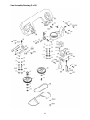
Saw Assembly – Parts
Index No. Part No. Description Size Qty
61 ............. 9180-61 .................... Cover .................................................................... .................................... 1
62 ............. TS-2248162 ............. Button Head Socket Screw .................................. M8x16 ......................... 2
64 ............. TS-1524041 ............. Set Screw ............................................................. M8x16 ......................... 1
65 ............. 9180-65 .................... Frame Pivot Shaft ................................................ .................................... 1
67 ............. 9180-67 .................... Tapered Bearing .................................................. .................................... 2
69 ............. 9180-69 .................... Cover .................................................................... .................................... 2
70 ............. 9180-70 .................... Washer ................................................................. .................................... 2
71 ............. 9180-71 .................... Motor .................................................................... 1HP, 3Ph, 230V .......... 1
72 ............. TS-1482051 ............. Hex Cap Screw .................................................... M6x25 ......................... 4
73 ............. TS-2361061 ............. Lock Washer ........................................................ M6 ............................... 4
74GA ........ 9180-74GA ............... Gear Box .............................................................. 3Ph, 1:28 .................... 1
75 ............. TS-1551071 ............. Lock Washer ........................................................ M10 ............................. 4
76 ............. TS-1505031 ............. Socket Head Cap Screw ...................................... M10x25 ....................... 4
77 ............. 9180-77 .................... Hose ..................................................................... ø6x750L ...................... 1
78 ............. 9180-78 .................... Hose Fitting .......................................................... ø8x1/4”PT ................... 1
79 ............. TS-1503041 ............. Socket Head Cap Screw ...................................... M6x16 ......................... 2
80 ............. 9180-80 .................... Coolant Block ....................................................... .................................... 1
81 ............. 9180-81 .................... Hose ..................................................................... ø6x240L ...................... 1
82 ............. 9180-82 .................... Valve .................................................................... 1/8” .............................. 2
83 ............. 9180-83 .................... Hose Fitting .......................................................... ø6x1/8”PT ................... 4
84 ............. 9180-84 .................... Bushing ................................................................ .................................... 1
85 ............. TS-1505031 ............. Socket Head Cap Screw ...................................... M10x25 ....................... 1
86 ............. 9180-86 .................... Washer ................................................................. .................................... 1
87 ............. 9180-87 .................... Round Head Key .................................................. 8x7x50 ........................ 1
88 ............. 9180-88 .................... Output Shaft ......................................................... .................................... 1
89 ............. 9180-89 .................... Round Head Key .................................................. 7x7x30 ........................ 1
90 ............. 9180-90 .................... Bearing ................................................................. .................................... 1
91 ............. 9180-91 .................... Spring ................................................................... .................................... 1
92 ............. 9180-92 .................... Spring ................................................................... .................................... 1
96 ............. 9180-96 .................... Idler Wheel ........................................................... .................................... 1
99 ............. 9180-99 .................... Nut ........................................................................ M20xP1 ....................... 1
100 ........... ................................. Blade (local purchase)...............................3/4”x.035x82”x5/8VT ............. 1
101 ........... 9180-101 .................. Drive Wheel.......................................................... .................................... 1
102 ........... 9180-102 .................. Drive Shaft Washer .............................................. .................................... 1
103 ........... TS-1491031 ............. Hex Cap Screw .................................................... M10x25 ....................... 1
104 ........... 9180-104 .................. Frame Back Cover ............................................... .................................... 1
105 ........... TS-1503041 ............. Socket Head Cap Screw ...................................... M6x16 ......................... 4
106 ........... TS-1550041 ............. Flat Washer .......................................................... M6 ............................... 4
111 ........... TS-2245162 ............. Button Head Socket Screw .................................. M5x16 ......................... 2
112 ........... TS-1550031 ............. Flat Washer .......................................................... M5 ............................... 2
113 ........... TS-1550031 ............. Flat Washer .......................................................... M5 ............................... 1
114 ........... TS-2245122 ............. Button Head Socket Screw .................................. M5x12 ......................... 1
161 ........... 9180-161 .................. Scale .................................................................... .................................... 1
162 ........... 9180-162 .................. Rivet ..................................................................... ø2X6 ........................... 2
165S ......... 9180-165 .................. Stock Stop Assembly ........................................... .................................... 1
165-1 ........ 9180-165-1 ............... Stop Block ............................................................ .................................... 1
165-2 ........ TS-1550061 ............. Flat Washer .......................................................... M8 ............................... 2
165-3 ........ 9180-165-3 ............... Locking Handle .................................................... .................................... 2
165-4 ........ 9180-165-4 ............... Stock Stop Rod .................................................... .................................... 1
165-5 ........ 9180-165-5 ............... Distance Set Rod ................................................. .................................... 1
165-6 ........ TS-2310142 ............. Hex Nut ................................................................ M14xP1.5 .....
............... 1
165-7 ........ 9180-165-7 ............... Scale .................................................................... .................................... 1
165-8 ........ 9180-165-8 ............... Rivet ..................................................................... ø2 ................................ 4
170 ........... 9180-170 .................. Hand Wheel ......................................................... .................................... 1
171 ........... 9180-171 .................. Pin ........................................................................ ø5x35 .......................... 1
Page is loading ...
Page is loading ...
Page is loading ...
Page is loading ...
Page is loading ...
Page is loading ...
Page is loading ...
Page is loading ...
-
 1
1
-
 2
2
-
 3
3
-
 4
4
-
 5
5
-
 6
6
-
 7
7
-
 8
8
-
 9
9
-
 10
10
-
 11
11
-
 12
12
-
 13
13
-
 14
14
-
 15
15
-
 16
16
-
 17
17
-
 18
18
-
 19
19
-
 20
20
-
 21
21
-
 22
22
-
 23
23
-
 24
24
-
 25
25
-
 26
26
-
 27
27
-
 28
28


JET J-9180-3 Owner's manual
- Type
- Owner's manual
- This manual is also suitable for
Ask a question and I''ll find the answer in the document
Finding information in a document is now easier with AI
Related papers
Other documents
-
Franklin Brass 211-5SS Installation guide
-
Parkside PBS 350 A1 Operating And Safety Instructions Manual
-
KAKA INDUSTRIAL BS-1018B User manual
-
King Canada KC-712DS User manual
-
Wilton 7020/7040 User manual
-
Unbranded 1300003 Installation guide
-
King Industrial KC-227-6 User manual
-
 Northern Industrial Tools 145765 User manual
-
-
