Page is loading ...

OpenSwitch OPX Conguration Guide
Release 2.1.0

2017 - 7
Rev. A02

Contents
1 Network conguration....................................................................................................................................4
2 Interfaces...................................................................................................................................................... 5
Physical ports..................................................................................................................................................................... 6
Fan-out interfaces..............................................................................................................................................................6
Port-channel/bond interfaces.......................................................................................................................................... 7
VLAN interfaces................................................................................................................................................................. 8
3 Layer 2 bridging.............................................................................................................................................9
VLAN bridging.................................................................................................................................................................... 9
Link layer discovery protocol............................................................................................................................................11
Spanning-tree provisioning...............................................................................................................................................11
4 Layer 3 routing............................................................................................................................................. 13
IPv4 routing....................................................................................................................................................................... 13
IPv6 routing....................................................................................................................................................................... 14
Neighbor table entries......................................................................................................................................................14
Next-hop routing.............................................................................................................................................................. 15
L3 routing topology.......................................................................................................................................................... 15
Quagga routing..................................................................................................................................................................17
Routing using Quagga......................................................................................................................................................19
5 Security.......................................................................................................................................................24
6 Monitoring...................................................................................................................................................25
sFlow provisioning............................................................................................................................................................25
Port statistics................................................................................................................................................................... 26
7 Support resources....................................................................................................................................... 30
Contents
3

Network conguration
OpenSwitch OPX supports the ability to model and congure various networking features in the network processing unit (NPU) using two
methods—Linux commands and CPS APIs. This information describes how to program networking features using Linux commands and
open source applications.
See Programmability in the OpenSwitch OPX Developers Guide for a description of the CPS framework, and detailed information on using
the CPS API for conguration.
OpenSwitch OPX network functionality is handled by the network adaptation service (NAS) which listens to netlink events for Layer 2 and
Layer 3 congurations, and programs the NPU.
NOTE: Layer 2 LLDP conguration is not available when using the CPS
API.
Linux command — open source application
• Interfaces — physical, link aggregation (LAG), VLAN
• Layer 2 bridging — LLDP, STP, VLAN
• Layer 3 routing — ECMP, IPv4, IPv6, unicast
CPS API conguration
• Interfaces — physical, link aggregation (LAG), VLAN, Fanout (script)
• Layer 2 bridging — MAC address table, STP, VLAN
• Layer 3 routing — ECMP, IPv4, IPv6, unicast
• Security — QoS and ACL
• Monitoring — port mirroring, sFlow, and port and VLAN statistics
Dell-provided commands
These features are not supported using standard Linux commands but can be congured using the Dell EMC-provided utilities.
• Fan-out (4x10G) interface conguration
• Layer 2 MAC address table conguration
• QoS and ACL conguration
• Port monitoring, sFlow conguration, and port and VLAN statistics
1
4 Network conguration
Interfaces
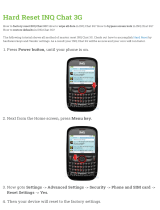
You can create and manage physical and virtual interfaces—physical port interfaces are ports on the NPU and do not include the
Management port. Each physical port on the NPU maps to a data port on the front panel of the device.
Applications access physical and virtual ports using mapped Linux interfaces. The software allocates an ifindex for each Linux interface,
and the value is used in CPS APIs to refer to a Linux interface.
Map ports to Linux interfaces
Each physical port is mapped to an internal Linux interface:
eNSS-PPP-F.vvv
• e — Ethernet port
• N — node ID (set to 1)
• SS — slot number (set to 01)
• PPP — port number (1 to 999)
• F — number of a 4x10G fan-out port (0 to 9)
• vvv — VLAN ID number (0 to 4095)
The e101-031-0 interface refers to physical port 31 without a fan-out—e101-005-4 identies fanout port 4 on physical port 5, and
e101-001-2 identies fanout port 2 on physical port 1.
Interfaces are created during system boot up and represent the physical ports on the NPU in a one-to-one mapping.
Internal interfaces allow applications to congure physical port parameters, such as MTU, port state, and link state. Interfaces also provide
packet input/output functionality and support applications sending and receiving control plane packets.
Map CPU port to Linux interface
The software creates a dedicated interface (npu0) that maps to the CPU port. Congure control plane policy (CoPP) queue rates by
specifying npu0 as the port in the QoS CPS API.
Topics:
• Physical ports
2
Interfaces 5

• Fan-out interfaces
• Port-channel/bond interfaces
• VLAN interfaces
Physical ports
Physical ports are administratively down by default. Each interface has a reserved MAC hardware address derived from the system MAC
address. Use standard Linux commands to congure physical interface parameters.
Set MTU
$ ip link set dev e101-002-0 mtu 1400
Show MTU
$ ip link show e101-002-0
17: e101-002-0: <BROADCAST,MULTICAST> mtu 1400 qdisc noop state DOWN mode DEFAULT group default
qlen 500
link/ether 90:b1:1c:f4:ab:f2 brd ff:ff:ff:ff:ff:ff
alias NAS## 0 29
Congure L3 IPv4 address
$ ip addr add 10.1.1.1/24 dev e101-001-0
Congure L3 IPv6 address
$ ip -6 addr add 2000::1/64 dev e101-001-0
View interface parameters
$ ip addr show e101-001-0
16: e101-001-0: <BROADCAST,MULTICAST> mtu 1500 qdisc noop state DOWN group default qlen 500
link/ether 90:b1:1c:f4:ab:ee brd ff:ff:ff:ff:ff:ff
inet 10.1.1.1/24 scope global e101-001-0
valid_lft forever preferred_lft forever
inet6 2000::1/64 scope global tentative
valid_lft forever preferred_lft forever
See Application examples in the OpenSwitch OPX Developers Guide for examples of how to program physical port conguration using the
CPS API.
Fan-out interfaces
Using a breakout cable, you can split a 40GbE physical port into four (quad) 10GbE SFP+ ports (if supported by the NPU). Each 4x10G
port is represented by a Linux interface with a fan-out eld in the interface name that identies the 4x10G port.
Use the opx-config-fanout script to congure fan-out interfaces. This script allows you to fan-out a 40GbE port or disable the
fanned-out 4x10G conguration and return the physical port to 40G operation.
opx-config-fanout portID [true | false]
• true enables 4x10G fan-out on a 40GbE port
• false disables 4x10G fan-out on a 40GbE port
Congure fan-out interface
$ opx-config-fanout e101-005-0 true
Key: 1.20.1310766.1310754.1310755.1310756.1310757.
base-port/physical/unit-id = 0
base-port/physical/phy-media = 1
base-port/physical/front-panel-number = 0
6
Interfaces

base-port/physical/loopback = 0
base-port/physical/hardware-port-id = 45
base-port/physical/npu-id = 0
base-port/physical/fanout-mode = 4
base-port/physical/breakout-capabilities = 4,2
base-port/physical/port-id = 45
base-port/physical/slot-id = 0
Deleting.. e101-005-0
Completed...
Creating interface e101-005-1
Creating interface e101-005-2
Creating interface e101-005-3
Creating interface e101-005-4
Successfully created interfaces...
Port-channel/bond interfaces
A port-channel or link aggregation group (LAG) corresponds to a bond interface, which aggregates multiple physical interfaces into one
virtual interface for load-balancing and link failovers. A LAG and a bond interface both refer to a link aggregation group. LAG refers to an
NPU conguration, while
bond interface refers to a Linux conguration.
NOTE: A Linux bond interface must be up before you can add member ports.
Create bond interface
$ ip link add bond1 type bond mode balance-rr miimon 50
Bring up bond interface
$ ip link set dev bond1 up
$ ip link show|grep bond1
50: bond1: <BROADCAST,MULTICAST,MASTER,UP,LOWER_UP> mtu 1500 qdisc noqueue state UNKNOWN mode
DEFAULT group default
Add port to bind interface
$ ip link set e101-010-0 master bond1
$ ip link show | grep bond1
12: e101-010-0: <BROADCAST,MULTICAST,SLAVE,UP,LOWER_UP> mtu 1500 qdisc mq master bond1 state UP
mode DEFAULT group default qlen 500
50: bond1: <BROADCAST,MULTICAST,MASTER,UP,LOWER_UP> mtu 1500 qdisc noqueue state UP mode
DEFAULT group default
Congure IP address on bond interface
$ ip addr add 20.1.1.1/24 dev bond1
$ ifconfig bond1
bond1 Link encap:Ethernet HWaddr 90:b1:1c:f4:9d:60
inet addr:20.1.1.1 Bcast:0.0.0.0 Mask:255.255.255.0
inet6 addr: fe80::8480:fcff:fe2f:d93b/64 Scope:Link
UP BROADCAST RUNNING MASTER MULTICAST MTU:1500 Metric:1
RX packets:66 errors:0 dropped:1 overruns:0 frame:0
TX packets:77 errors:0 dropped:0 overruns:0 carrier:0
collisions:0 txqueuelen:0
RX bytes:4224 (4.1 KiB) TX bytes:15648 (15.2 KiB)
Delete port from bond interface
$ ip link set e101-010-0 nomaster
$ ip link show | grep bond1
49: bond1: <NO-CARRIER,BROADCAST,MULTICAST,MASTER,UP> mtu 1500 qdisc noqueue state DOWN mode
DEFAULT group default
Delete bond interface
$ ip link delete bond1
$ ip link show | grep bond1
Interfaces
7

See www.kernel.org for more information about how to use bond interfaces, and see Application examples in the OpenSwitch OPX
Developers Guide for more information on programming a bond interface using the CPS API.
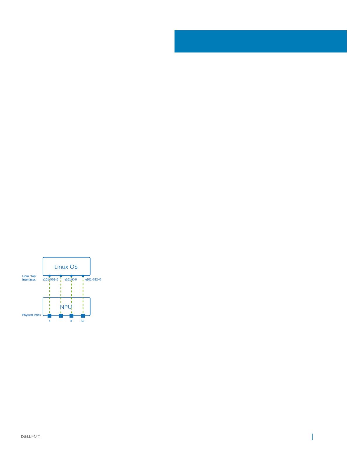
VLAN interfaces
Virtual LANs (VLANs) dene broadcast domains in a Layer 2 network, and an NPU VLAN entity is modeled as a separate Linux bridge
instance.
NPU entities (VLANs) are mapped to Linux entities (bridges). An NPU VLAN entity uses the MAC address from the rst port added as its
member port. The bridge interface is operationally up when at least one of its member interfaces is up. You can assign IP addresses to
multiple bridge interfaces to create an inter-VLAN routing domain.
Congure IP address on bridge interface
$ brctl show
bridge name bridge id STP enabled interfaces
br100 8000.90b11cf49d3c no e101-001-0.100
$ ip addr add 100.1.1.1 dev br100
$ ifconfig br100
br100 Link encap:Ethernet HWaddr 90:b1:1c:f4:9d:3c
inet addr:100.1.1.1 Bcast:0.0.0.0 Mask:255.255.255.255
inet6 addr: fe80::92b1:1cff:fef4:9d3c/64 Scope:Link
UP BROADCAST RUNNING MULTICAST MTU:1500 Metric:1
RX packets:0 errors:0 dropped:0 overruns:0 frame:0
TX packets:7 errors:0 dropped:0 overruns:0 carrier:0
collisions:0 txqueuelen:0
RX bytes:0 (0.0 B) TX bytes:738 (738.0 B)
8
Interfaces

Layer 2 bridging
OpenSwitch OPX supports Layer 2 bridging and includes VLAN bridging, spanning-tree provisioning (STP), link layer discovery protocol
(LLDP), and media access control (MAC) address forwarding. OpenSwitch OPX provides a CPS data model for conguring and managing
the MAC address forwarding database using the CPS API.
You can congure Layer 2 MAC addresses and VLAN learning and forwarding properties in support of Layer 2 bridging. The device learns
unicast MAC addresses to avoid ooding the packets to all the ports in a bridge domain. If the bridge receives a control protocol data unit
(PDU) which does not have a corresponding protocol congured, the control PDU is considered as an unknown multicast data packet, and
the packets are ooded across all ports that are part of the same bridge domain. If the bridge has the protocol corresponding to the PDU
congured, the control PDU is considered as a control packet and is processed by the routing engine.
See the OpenSwitch OPX Developers Guide for more information on writing applications that access the CPS API to congure Layer 2, and
using YANG models to congure the MAC address forwarding database.
Topics:
• VLAN bridging
• Link layer discovery protocol
• Spanning-tree provisioning
VLAN bridging
OpenSwitch OPX supports Layer 2 VLAN bridging by modeling each NPU VLAN entity as a separate Linux bridge instance. Each physical
or LAG port that is a VLAN member is modeled by adding its corresponding Linux interface to the bridge instance. See Application
examples in the OpenSwitch OPX Developers Guide for more information on creating a VLAN and assigning members.
To create a VLAN using the Linux bridge, create the bridge instance and then add a tagged member to the new bridge instance.
OpenSwitch OPX determines the VLAN ID associated with each bridge instance using the VLAN ID of the rst tagged member port
assigned to the bridge instance. The VLAN is created only after you add the rst tagged member to the bridge.
3
Layer 2 bridging 9

1 Create a bridge instance for the VLAN—br100 is the name of the bridge instance used to model the VLAN, and OpenSwitch OPX
does not derive the VLAN ID from the name.
$ brctl addbr br100
2 Add a tagged port to the VLAN to ensure that the Linux interface mapped to the port being added does not have an IP address.
$ ifconfig e101-001-0
e101-001-0 Link encap:Ethernet HWaddr 90:b1:1c:f4:9d:3c
inet addr:1.1.1.1 Bcast:1.1.1.255 Mask:255.255.255.0
BROADCAST MULTICAST MTU:1500 Metric:1
RX packets:0 errors:0 dropped:0 overruns:0 frame:0
TX packets:2221 errors:0 dropped:0 overruns:0 carrier:0
collisions:0 txqueuelen:500
RX bytes:0 (0.0 B) TX bytes:523446 (511.1 KiB)
If the interface already has an IP address, remove the IP address before continuing to the next step.
$ ip addr flush dev e101-001-0
3 Create a tagged virtual link—a Linux interface can only belong to a single bridge instance. To add the same interface to multiple VLAN
domains, create a separate Linux virtual link for each VLAN in which the port is a member. Create a virtual tagged link for the
e101-001-0 Linux interface in VLAN 100—the .100 sux in the Linux interface name indicates that the interface is VLAN tagged.
$ ip link add link e101-001-0 name e101-001-0.100 type vlan id 100
4 Add the tagged virtual link to the VLAN to add the newly created virtual link to the Linux bridge instance created in Step 1.
OpenSwitch OPX creates the VLAN and adds the physical port mapped to the e101-001-0 Linux interface as a tagged member of
the VLAN.
$ brctl addif br100 e101-001-0.100
5 Verify the VLAN conguration.
$ brctl show
bridge name bridge id STP enabled interfaces
br100 8000.90b11cf49d3c no e101-001-0.100
Add untagged member to VLAN
You can add a Linux interface directly to a Linux bridge without creating a separate VLAN-specic virtual link. Note that in the example the
interface does not have the .100 sux, which means the interface is an untagged VLAN member.
$ brctl addif br100 e101-002-0
A physical port can be an untagged member of only a single VLAN—a physical port can be added as a tagged member of multiple VLANs.
$ brctl show
bridge name bridge id STP enabled interfaces
br100 8000.90b11cf49d3c no e101-001-0.100
e101-002-0
Add port to multiple VLAN domains
To add the same port to a second VLAN, create another VLAN tagged virtual link on the e101-001-0 interface, then add the new virtual
link to the Linux bridge instance.
$ brctl addbr br200
$ ip link add link e101-001-0 name e101-001-0.200 type vlan id 200
$ brctl addif br200 e101-001-0.200
NOTE
: All interfaces in a bridge instance must be either untagged or have the same tagged VLAN ID—you cannot congure
e101-001-0.100 and e101-002-0.200 in the same Linux bridge instance.
$ brctl show
bridge name bridge id STP enabled interfaces
br100 8000.90b11cf49d3c no e101-001-0.100
e101-002-0
br200 8000.90b11cf49d3c no e101-001-0.200
Add Linux bond interface to VLAN domain
10
Layer 2 bridging
Add a Linux bond interface to a VLAN domain—bond1 is a Linux interface that maps to a LAG port in the NPU. Use the command to add
the LAG port to the VLAN associated with the bridge instance in the NPU.
$ ip link add link bond1 name bond1.200 type vlan id 200
$ brctl addif br200 bond1.200
Remove VLAN member from VLAN
$ brctl delif br200 e101-001-0.100
Delete VLAN
$ brctl delbr br200
Link layer discovery protocol
OpenSwitch OPX supports the link layer discovery protocol (LLDP) daemon on Linux interfaces.
LLDP daemon
$ lldpcli show neighbors
---------------------------------------------------------------------
LLDP neighbors:
---------------------------------------------------------------------
Interface: e101-003-0, via: LLDP, RID: 3, Time: 0 day, 01:17:18
Chassis:
ChassisID: mac 90:b1:1c:f4:9d:3b
SysName: OPEN
Capability: Repeater, on
Capability: Bridge, on
Capability: Router, on
Port:
PortID: ifalias ethernet1/1/3
----------------------------------------------------------------------
Spanning-tree provisioning
OpenSwitch OPX supports spanning-tree provisioning (STP) using the CPS API including:
• Create a new spanning-tree group
• Add VLANs to a spanning-tree group
• Remove VLANs from a spanning-tree group
• Change the STP state of ports mapped to a spanning-tree group
• Delete a spanning-tree group
This enables OpenSwitch OPX to run any of the spanning-tree protocols such as STP, RSTP, PVST, and MSTP.
Layer 2 bridging
11

NOTE: OpenSwitch OPX does not support RSTP, MSTP, and RPVST in a Linux bridge due to a Linux kernel limitation. STP is not
supported on a bridge which has multiple member interfaces with dierent VLAN IDs.
See YANG model reference in the OpenSwitch OPX Developers Guide for more information on the dell-open-stp.yang model for the
supported STP parameters.
Linux STP does not support the concept of spanning-tree groups. In Linux, you can enable spanning tree independently in each bridge
instance. OpenSwitch OPX treats STP enabled in a bridge instance as a separate spanning-tree group for each VLAN. If a Linux bridge
contains only untagged ports, the software does not support STP on the bridge.
1 Create a VLAN in the Linux bridge (see VLAN bridging).
2 Enable STP on the bridge, then view the conguration.
$ brctl stp br100 on
$ brctl show br100
bridge name bridge id STP enabled interfaces
br100 8000.90b11cf4a918 yes e101-001-0.100
$ brctl showstp br100
br100
bridge id 8000.90b11cf4a918
designated root 8000.90b11cf4a918
root port 0 path cost 0
max age 20.00 bridge max age 20.00
hello time 2.00 bridge hello time 2.00
forward delay 15.00 bridge forward delay 15.00
ageing time 300.00
hello timer 0.00 tcn timer 0.00
topology change timer 0.00 gc timer 0.00
flags
e101-001-0.100 (1)
port id 8001 state disabled
designated root 8000.90b11cf4a918 path cost 100
designated bridge 8000.90b11cf4a918 message age timer 0.00
designated port 8001 forward delay timer 0.00
designated cost 0 hold timer 0.00
flags
Disable STP on bridge
$ brctl stp br100 off
View bridge conguration
$ brctl show br100
bridge name bridge id STP enabled interfaces
br100 8000.90b11cf4a918 no e101-001-0.100
When you enable STP on a bridge which has tagged VLAN interfaces, OpenSwitch OPX creates a new spanning-tree group and associates
the VLAN ID of the bridge with the newly created spanning-tree group. When you delete a bridge from the Linux kernel, the corresponding
NPU spanning-tree group is deleted.
12
Layer 2 bridging

Layer 3 routing
OpenSwitch OPX supports unicast routing over Linux interfaces using routes in the Linux kernel routing table. Applications can also use the
CPS API to congure routes. This information describes how to congure Layer 3 unicast routing to provision the NPU.
The OpenSwitch OPX routing subsystem manages the forwarding information base (FIB). The routing subsystem programs routes with
resolved next hops using ARP/Neighbor table entries received from the Linux kernel.
Topics:
• IPv4 routing
• IPv6 routing
• Neighbor table entries
• Next-hop routing
• L3 routing topology
• Quagga routing
• Routing using Quagga
IPv4 routing
Use the iproute command to create a route. A routing table entry consists of a destination IP address prex and at least one next-hop
address or a Linux interface.
Congure static route
$ ip route show
default dev eth0 scope link
3.3.3.0/24 dev e101-003-0 proto kernel scope link src 3.3.3.1
$ ip route add 11.10.10.0/24 dev e101-003-0
4
Layer 3 routing 13

$ ip route show
default dev eth0 scope link
3.3.3.0/24 dev e101-003-0 proto kernel scope link src 3.3.3.1
11.10.10.0/24 dev e101-003-0 scope link
Congure static route with next-hop
$ ip route add 30.30.30.0/24 via 3.3.3.3
$ ip route show
default dev eth0 scope link
3.3.3.0/24 dev e101-003-0 proto kernel scope link src 3.3.3.1
30.30.30.0/24 via 3.3.3.3 dev e101-003-0
Delete static route
$ ip route delete 11.10.10.0/24
$ ip route show
default dev eth0 scope link
3.3.3.0/24 dev e101-003-0 proto kernel scope link src 3.3.3.1
To add a persistent static route that is saved after a reboot, congure the route in the /etc/network/interfaces conguration le.
See Application examples in the OpenSwitch OPX Developers Guide for more information on how to congure routing using the CPS API.
IPv6 routing
Add, delete, or modify IPv6 routes and next-hops in the routing table.
Add IPv4 route
$ ip -6 route add 5::5/64 via 3::3
View IPv6 route
$ ip -6 route show
3::/64 dev e101-003-0 proto kernel metric 256
5::/64 via 3::3 dev e101-003-0 metric 1024
Monitor IPv6 routing
$ ip monitor
30.30.30.0/24 via 3.3.3.3 dev e00-3
3::/64 via 3::3 dev e101-003-0 metric 1024
5::/64 via 3::3 dev e101-003-0 metric 1024
See Application examples in the OpenSwitch OPX Developers Guide for more information on how to congure routing using the CPS API.
Neighbor table entries
OpenSwitch OPX uses ARP and neighbor table entries to resolve adjacencies by using the host IP address-to-MAC address binding. The
ARP table is used for IPv4 routing—the neighbor table is used for IPv6 routing.
View kernel ARP table entries
$ arp -n
Address HWtype HWaddress Flags Mask Iface 3.3.3.4 ether 90:b1:1c:f4:9d:44 C e101-003-0
View IPv6 neighbor table
$ ip -6 neighbor
14
Layer 3 routing

Congure IPv6 address
$ ifconfig e101-003-0 inet6 add 3::1/64
$ ifconfig e101-003-0
e101-003-0 Link encap:Ethernet HWaddr 90:b1:1c:f4:a8:ea
inet addr:3.3.3.1 Bcast:3.3.3.255 Mask:255.255.255.0
inet6 addr: 3::1/64 Scope:Global
inet6 addr: fe80::92b1:1cff:fef4:a8ea/64 Scope:Link
UP BROADCAST RUNNING MULTICAST MTU:1500 Metric:1
RX packets:532 errors:0 dropped:0 overruns:0 frame:0
TX packets:173 errors:0 dropped:0 overruns:0 carrier:0
collisions:0 txqueuelen:500
RX bytes:46451 (45.3 KiB) TX bytes:25650 (25.0 KiB)
View IPv6 neighbor table
$ ip -6 neighbor show
3::3 dev e101-003-0 lladdr 90:b1:1c:f4:9d:44 router REACHABLE
Check connectivity to IPv6 neighbor
$ ping6 3::3
PING 3::3(3::3) 56 data bytes
64 bytes from 3::3: icmp_seq=1 ttl=64 time=1.74 ms
$ tcpdump -i e101-003-0
tcpdump: verbose output suppressed, use -v or -vv for full protocol decode
listening on e101-003-0, link-type EN10MB (Ethernet), capture size 262144 bytes
04:30:17.053115 IP6 3::1 > 3::3: ICMP6, echo request, seq 8, length 64
Next-hop routing
The Linux networking stack supports ECMP by adding multiple next-hops to a route, and the kernel provides limited support for IPv6
multipath routing.
Congure next-hop routing
$ ip route add 40.40.40.0/24 nexthop via 3.3.3.6 nexthop via 4.4.4.7
View ECMP conguration
$ ip route show
default dev eth0 scope link
3.3.3.0/24 dev e101-003-0 proto kernel scope link src 3.3.3.1
40.40.40.0/24
nexthop via 3.3.3.6 dev e101-003-0 weight 1
nexthop via 4.4.4.7 dev e101-004-0 weight 1
L3 routing topology
Use ip addr add or ifconfig to congure an interface.
See Application examples in the OpenSwitch OPX Developers Guide for more information on how to congure routing using the CPS API.
Congure IP address on R1
$ ip addr add 10.1.1.1/24 dev e101-007-0
$ ip addr add 11.1.1.1/24 dev e101-001-0
Layer 3 routing
15

Congure IP address on R2
$ ip addr add 10.1.1.2/24 dev e101-007-0
$ ip addr add 12.1.1.1/24 dev e101-001-0
Verify conguration on R1
$ ip addr show e101-007-0
16: e101-007-0: <BROADCAST,MULTICAST,UP,LOWER_UP> mtu 1500 qdisc mq state UP group default qlen
500
link/ether 74:e6:e2:f6:af:87 brd ff:ff:ff:ff:ff:ff
inet 10.1.1.1/24 scope global e101-007-0
valid_lft forever preferred_lft forever
inet6 fe80::76e6:e2ff:fef6:af87/64 scope link
valid_lft forever preferred_lft forever
$ ip addr show e101-001-0
10: e101-001-0: <BROADCAST,MULTICAST,UP,LOWER_UP> mtu 1500 qdisc mq state UP group default qlen
500
link/ether 74:e6:e2:f6:af:81 brd ff:ff:ff:ff:ff:ff
inet 11.1.1.1/24 scope global e101-001-0
valid_lft forever preferred_lft forever
inet6 fe80::76e6:e2ff:fef6:af81/64 scope link
valid_lft forever preferred_lft forever
Verify conguration on R2
$ ip addr show e101-007-0
16: e101-007-0: <BROADCAST,MULTICAST,UP,LOWER_UP> mtu 1500 qdisc mq state UP group default qlen
500
link/ether 74:e6:e2:f6:ba:87 brd ff:ff:ff:ff:ff:ff
inet 10.1.1.2/24 scope global e101-007-0
valid_lft forever preferred_lft forever
inet6 fe80::76e6:e2ff:fef6:ba87/64 scope link
valid_lft forever preferred_lft forever
$ ip addr show e101-001-0
10: e101-001-0: <BROADCAST,MULTICAST,UP,LOWER_UP> mtu 1500 qdisc mq state UP group default qlen
500
link/ether 74:e6:e2:f6:ba:81 brd ff:ff:ff:ff:ff:ff
inet 12.1.1.1/24 scope global e101-001-0
valid_lft forever preferred_lft forever
inet6 fe80::76e6:e2ff:fef6:ba81/64 scope link
valid_lft forever preferred_lft forever
Enable interfaces on R1 and R2
$ ip link set dev e101-007-0 up $ip link set dev e101-001-0 up
Congure static route to server on R1
$ ip route add 12.1.1.0/24 via 10.1.1.2
Congure static route to server on R2
$ ip route add 11.1.1.0/24 via 10.1.1.1
Check connectivity from server 2
$ ping 11.1.1.2
PING 11.1.1.2 (11.1.1.2) 56(84) bytes of data.
64 bytes from 11.1.1.2: icmp_seq=1 ttl=64 time=0.922 ms
^C
--- 11.1.1.2 ping statistics ---
1 packets transmitted, 1 received, 0% packet loss, time 0ms
rtt min/avg/max/mdev = 0.922/0.922/0.922/0.000 ms
$ping 10.1.1.2
PING 10.1.1.2 (10.1.1.2) 56(84) bytes of data.
64 bytes from 10.1.1.2: icmp_seq=1 ttl=64 time=0.709 ms
^C
--- 10.1.1.2 ping statistics ---
16
Layer 3 routing
1 packets transmitted, 1 received, 0% packet loss, time 0ms
rtt min/avg/max/mdev = 0.709/0.709/0.709/0.000 ms
View ARP table on R1
$ arp -n
Address HWtype HWaddress Flags Mask Iface
11.1.1.2 ether 00:00:00:1d:9a:bd C e101-001-0
10.1.1.2 ether 74:e6:e2:f6:ba:87 C e101-007-0
View ARP table on R2
$ arp -n
Address HWtype HWaddress Flags Mask Iface
10.1.1.1 ether 74:e6:e2:f6:af:87 C e101-007-0
12.1.1.2 ether 00:00:00:1d:9a:be C e101-001-0
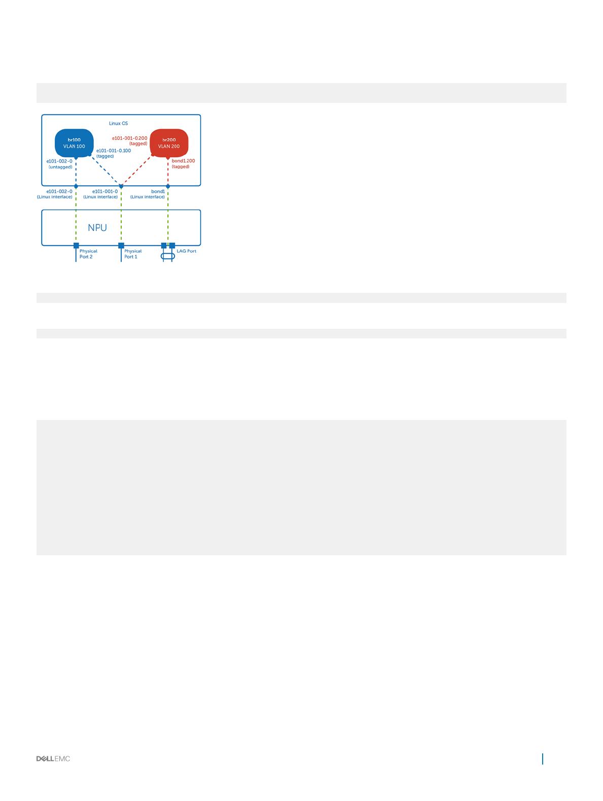
Quagga routing
Quagga is an open-source routing application that provides OSPFv2, OSPFv3, RIPv1 and v2, RIPng, and BGP-4 functionality.
The Quagga architecture consists of a core daemon zebra, which acts as an abstraction layer to the underlying Linux kernel and presents a
Zserv API over a Unix or TCP socket to Quagga clients. The Zserv clients implement a routing protocol and communicate routing updates
to the zebra daemon. See github.com/opensourcerouting/quagga for complete information.
Install Quagga
$ apt-get install -y quagga
Reading package lists... Done
Building dependency tree
Reading state information... Done
The following NEW packages will be installed:
quagga
0 upgraded, 1 newly installed, 0 to remove and 0 not upgraded.
Need to get 1217 kB of archives.
After this operation, 6323 kB of additional disk space will be used.
Get:1 http://10.11.56.31/debian/ jessie/main quagga amd64 0.99.23.1-1 [1217 kB]
Fetched 1217 kB in 0s (12.2 MB/s)
Preconfiguring packages ...
Selecting previously unselected package quagga.
(Reading database ... 46597 files and directories currently installed.)
Preparing to unpack .../quagga_0.99.23.1-1_amd64.deb ...
Unpacking quagga (0.99.23.1-1) ...
Processing triggers for systemd (215-17) ...
Processing triggers for man-db (2.7.0.2-5) ...
Setting up quagga (0.99.23.1-1) ...
Processing triggers for systemd (215-17) ...
Processing triggers for libc-bin (2.19-18) ...
Layer 3 routing
17

Quagga daemons and the debian.conf le are stored in the /etc/quagga directory. All routing protocol daemons installed with
Quagga are disabled by default. You must enable the zebra daemon to install the routes in the kernel routing table.
1 Open the daemons le for editing and change the daemon status to yes.
$ vim /etc/quagga/daemons
zebra=yes
bgpd=yes
ospfd=no
ospf6d=no
ripd=no
ripngd=no
isisd=no
babeld=no
2 Create the vtysh.conf and Quagga.conf conguration les.
$ cp /usr/share/doc/quagga/examples/vtysh.conf.sample /etc/quagga/vtysh.conf touch /etc/
quagga/Quagga.conf
3 Restart the Quagga service.
$ /etc/quagga# service quagga restart
4 View the status of Quagga protocol daemons.
$ /etc/quagga# service quagga status
? quagga.service - LSB: start and stop the Quagga routing suite
Loaded: loaded (/etc/init.d/quagga)
Active: active (running) since Tue 2016-02-16 17:47:25 UTC; 4s ago
Process: 5078 ExecStop=/etc/init.d/quagga stop (code=exited, status=0/SUCCESS)
Process: 5097 ExecStart=/etc/init.d/quagga start (code=exited, status=0/SUCCESS)
CGroup: /system.slice/quagga.service
??5111 /usr/lib/quagga/zebra --daemon -A 127.0.0.1
??5115 /usr/lib/quagga/bgpd --daemon -A 127.0.0.1
??5121 /usr/lib/quagga/watchquagga --daemon zebra bgpd
Feb 16 17:47:25 OPX quagga[5097]: Loading capability module if not yet done.
Feb 16 17:47:25 OPX quagga[5097]: Starting Quagga daemons (prio:10): zebra...d.
Feb 16 17:47:25 OPX quagga[5097]: Starting Quagga monitor daemon: watchquagga.
Feb 16 17:47:25 OPX watchquagga[5121]: watchquagga 0.99.23.1 watching [zebr...]
Feb 16 17:47:25 OPX systemd[1]: Started LSB: start and stop the Quagga rou...e.
Feb 16 17:47:25 OPX watchquagga[5121]: bgpd state -> up : connect succeeded
Feb 16 17:47:25 OPX watchquagga[5121]: zebra state -> up : connect succeeded
Hint: Some lines were ellipsized, use -l to show in full
5 Remove the ! character to the left of the service integrated-vtysh-config option in the vtysh.conf le.
$ /etc/quagga/vtysh.conf
!
! Sample
!
service integrated-vtysh-config
hostname quagga-router
username root nopassword
6 Enable paging in the /etc/environment le.
$ echo VTYSH_PAGER=more > /etc/environment
7 Source the environment le before you access the Quagga shell.
$ source /etc/environment
8 Access the Quagga shell.
$ vtysh
Hello, this is Quagga (version 0.99.23.1)
Copyright 1996-2005 Kunihiro Ishiguro, et al.
OPX#
9 Save the conguration changes.
$ write memory
Building Configuration...
Integrated configuration saved to /etc/quagga/Quagga.conf
[OK]
18
Layer 3 routing

See github.com/opensourcerouting/quagga for complete information.
Routing using Quagga
This use case describes how to congure BGP using Quagga in a spine/leaf network. See github.com/opensourcerouting/quagga for
complete information.
Link Network Link Nodes BGP AS Number
Leaf1-to-Spine1 10.1.1.0/24 Leaf1 64501
Spine1 64555
Leaf1-to-Spine2 20.1.1.0/24 Leaf1 64501
Spine2 64555
Leaf2-to-Spine1 40.1.1.0/24 Leaf2 64502
Spine1 64555
Leaf2-to-Spine2 30.1.1.0/24 Leaf2 64502
Spine2 64555
Leaf1-to-Server1 11.1.1.0/24 Leaf1 64501
Leaf2-to-Server2 12.1.1.0/24 Leaf2 64502
1 Congure the IP addresses to Spine1, Spine2, and Server1 from Leaf1.
leaf1(config)# interface e101-049-0
leaf1(conf-if-e101-049-0)# ip address 10.1.1.1/24
leaf1(conf-if-e101-049-0)# no shutdown
leaf1(conf-if-e101-049-0)# exit
leaf1(config)# interface e101-051-0
leaf1(conf-if-e101-051-0)# ip address 20.1.1.1/24
leaf1(conf-if-e101-051-0)# no shutdown
leaf1(conf-if-e101-051-0)# exit
leaf1(config)# interface e101-001-0
leaf1(conf-if-e101-001-0)# ip address 11.1.1.1/24
leaf1(conf-if-e101-001-0)# no shutdown
2 Congure the IP addresses to Spine1, Spine2, and Server2 from Leaf2.
leaf2(config)# interface e101-032-0
leaf2(conf-if-e101-032-0)# ip address 30.1.1.1/24
leaf2(conf-if-e101-032-0)# no shutdown
leaf2(conf-if-e101-032-0)# exit
leaf2(config)# interface e101-020-0
leaf2(conf-if-e101-020-0)# ip address 40.1.1.1/24
leaf2(conf-if-e101-020-0)# no shutdown
leaf2(conf-if-e101-020-0)# exit
leaf2(config)# interface e101-001-0
Layer 3 routing
19

leaf2(conf-if-e101-001-0)# ip address 12.1.1.1/24
leaf2(conf-if-e101-001-0)# no shutdown
3 Congure the IP addresses to Leaf1 and Leaf2 from Spine1.
spine1(config)# interface e101-027-1
spine1(conf-if-e101-027-1)# ip address 10.1.1.2/24
spine1(conf-if-e101-027-1)# no shutdown
spine1(conf-if-e101-027-1)# exit
spine1(config)# interface e101-010-1
spine1(conf-if-e101-010-1)# ip address 40.1.1.2/24
spine1(conf-if-e101-010-1)# no shutdown
4 Congure the IP addresses to Leaf1 and Leaf2 from Spine2.
spine2(config)# interface e101-027-1
spine2(conf-if-e101-027-1)# ip address 20.1.1.2/24
spine2(conf-if-e101-027-1)# no shutdown
spine2(conf-if-e101-027-1)# exit
spine2(config)# interface e101-018-1
spine2(conf-if-e101-018-1)# ip address 30.1.1.2/24
spine2(conf-if-e101-018-1)# no shutdown
spine2(conf-if-e101-018-1)# exit
5 Congure BGP to Spine1 and Spine2 from Leaf 1.
leaf1(config)# router bgp 64501
leaf1(conf-router-bgp-64501)# neighbor 10.1.1.2 remote-as 64555
leaf1(conf-router-bgp-64501)# neighbor 20.1.1.2 remote-as 64555
leaf1(conf-router-bgp-64501)# network 10.1.1.0/24
leaf1(conf-router-bgp-64501)# network 20.1.1.0/24
leaf1(conf-router-bgp-64501)# network 11.1.1.0/24
6 Congure BGP to Spine1 and Spine2 from Leaf 2.
leaf2(config)# router bgp 64502
leaf2(conf-router-bgp-64502)# neighbor 30.1.1.2 remote-as 64555
leaf2(conf-router-bgp-64502)# neighbor 40.1.1.2 remote-as 64555
leaf2(conf-router-bgp-64502)# network 12.1.1.0/24
leaf2(conf-router-bgp-64502)# network 30.1.1.0/24
leaf2(conf-router-bgp-64502)# network 40.1.1.0/24
7 Congure BGP to Leaf1 and Leaf2 from Spine1.
spine1(config)# router bgp 64555
spine1(conf-router-bgp-64555)# neighbor 10.1.1.1 remote-as 64501
spine1(conf-router-bgp-64555)# neighbor 40.1.1.1 remote-as 64502
spine1(conf-router-bgp-64555)# network 10.1.1.0/24
spine1(conf-router-bgp-64555)# network 40.1.1.0/24
8 Congure BGP to Leaf1 and Leaf2 from Spine 2.
spine2(config)# router bgp 64555
spine2(conf-router-bgp-64555)# neighbor 30.1.1.1 remote-as 64502
spine2(conf-router-bgp-64555)# neighbor 20.1.1.1 remote-as 64501
spine2(conf-router-bgp-64555)# network 30.1.1.0/24
spine2(conf-router-bgp-64555)# network 20.1.1.0/24
9 Congure ECMP from Leaf1 and Leaf2.
leaf1(config)# router bgp 64501
leaf1(conf-router-bgp-64501)# maximum-paths 16
leaf2(config)# router bgp 64502
leaf2(conf-router-bgp-64502)# maximum-paths 16
Verify spine/leaf conguration
1 Verify BGP neighbors from Leaf1 and Leaf2.
leaf1# show ip bgp sum
BGP router identifier 20.1.1.1, local AS number 64501
RIB entries 11, using 1232 bytes of memory
Peers 2, using 9136 bytes of memory
Neighbor V AS MsgRcvd MsgSent TblVer InQ OutQ Up/Down State/PfxRcd
10.1.1.2 4 64555 196 201 0 0 0 02:39:02 4
20
Layer 3 routing
/