Page is loading ...

REF:# SSUR001 DATE: 08/13/03
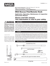
SURE STRONG™ WORK WINCH
Specification, System A
THESE INSTRUCTIONS MUST BE
PROVIDED TO THE USER.
MANAGEMENT AND USER MUST
READ AND UNDERSTAND THESE
INSTRUCTIONS;
FAILURE TO DO SO
COULD RESULT IN SERIOUS
INJURY OR DEATH.
Instructions for Application, Operation, Maintenance
& Inspection. Please read this manual. This
information is vital to your safety.
Sure-Strong™ Work Winch
P/N: SCE1074021050
• 3/16" (4.7mm) x 50 ft (15.2m), galvanized wire
rope installed, c/w 2.0 Ibs (1.0kg) line weight and
forged locking swivel hook
• total weight 22 Ibs (10kg)
• zinc chromate finish
• automatic load brake
• gear ratio 2.85:1
• tripod mounting bracket and locking pin
• 10" (25cm) removable winch handle with
mounting hardware
• safe working load 300 Ibs (136kg)
• rescue working load 600 lbs (272kg)
WINCH
DIMENSIONS
Spool diameter
Flange diameter
Spool width
A
B
C
D
E
F
G
H
J
K
L
M
S
T
inch cm
1.50 3.81
5.25 13.34
1.84 4.67
7.27 18.47
16.44 41.76
6.14 15.60
3.37 8.56
2.00 5.08
8.05 20.45
10.32 26.21
12.76 32.41
1.84 4.67
3.68 9.35
2.82 7.16
5.00 12.70
0.43 1.09
0.18 0.46
J
L
M
K
H C
D
A
G
E
B
F
handle
rotation
C
L
T
SCE1074021050
Copyright © 2001 MSA
All rights reserved. No part of this Catalogue covered
by the copyrights hereon may be reproduced or copied
in any form or by any means - graphics, electronic or
mechanical, including photocopying, recording, taping
or information storage and retrieval systems—without
the written permission of MSA.
WARNING
MSA Corporate Headquarters: P.O. Box 426, Pittsburgh, PA 15230, USA
Phone: 1-800-672-2222 Fax: 1-800-967-0398
• Web Site: www.msanet.com • e-mail: [email protected]

Specification, System B
Sure-Strong™ Work Winch
P/N.: SCE1074411200
• 3/16" (4.7mm) x 200ft (61m)
galvanized wire rope installed
c/w 2.0 lbs (1.0kg) line weight
and forged locking swivel hook
• total weight 48 lbs (21kg)
• zinc chromate finish
• automatic load brake
• gear ratio 3.83:1
• tripod mounting bracket and
locking pin
• 10" (25cm) removable winch
handle with mounting hardware
• safe working load 300 Ibs
(136kg)
• rescue working load 600 lbs
(272kg)
SHLAR001
FOR INSTALLATION ON 10' TRIPODS, FIRST UNWIND 15 FEET OF CABLE, INSTALL PULLEY.
THEN EXTEND TRIPOD LEGS TO WORKING HEIGHT AND INSTALL WINCH.
WINCH
DIMENSIONS
Spool diameter
Flange diameter
Spool width
A
B
C
D
E
F
G
H
J
K
L
M
S
T
inch cm
2.50 6.35
6.25 15.88
5.92 15.04
10.00 25.40
22.17 56.31
7.05 17.91
3.92 9.96
3.92 9.96
13.78 35.00
10.32 26.21
14.68 37.29
6.31 16.03
8.26 20.98
5.00 12.70
6.00 15.24
0.40 1.02
0.18 0.46
H
C
D
drum
A
C
L
F
B
G
handle
rotation
C
L
E
L
J
K
C
M
SCE1074411200
Pulley Specification
PULLEY
DIMENSIONS
U
V
W
X
Y
Z
inch cm
3.50 8.89
0.84 2.13
2.09 5.30
3.38 8.58
6.13 15.57
2.50 6.35
HEAD PULLEY #1
• 3.5" (8.9 cm) stainless
steel split pulley
• total weight: 2 lbs (1 kg)
Installation
THE WINCH SHOULD BE INSTALLED ON THE TRIPOD EVEN IF lT IS ANTICIPATED THAT
THE SYSTEM WILL ONLY BE USED FOR FALL PROTECTION. ALL CABLE MUST BE
REWOUND ON THE WINCH DRUM WHEN THE FALL ARREST SYSTEM IS IN USE. IF
POSSIBLE, INSTALL THE WORK WINCH BEFORE EXPOSING THE OPENING.
NOTE: LUBRICATE WINCH BEFORE INSTALLATION
X
z
C
L
W
V
U
Y
Copyright © 2001 MSA
2 0f 8

Installation
• Remove locking pin from work winch mounting bracket.
• Install winch on the inside of one tripod leg in the highest
adjustment hole (1).
• Apply tension to cable, unwind approximately five feet
from winch drum (turn winch handle counter clockwise)
and lay cable on working surface (2).
• Unfasten the pulley anchor bolt with two 1/2 wrenches
and rotate side plates to the open position. (3)
• Install cable onto pulley and close side plates.
• Inspect the nut and bolt for wear.
• Re-install bolt and nut through pulley anchor hole. Tighten
securely making sure the nylon retainer on the nut is
penetrated by the bolt threads. Ensure nylon retainer on
nut is not worn out by attempting to undo the nut by
hand. If nut can be loosened by hand, the nut must be
replaced. Tag and Remove part from service.
Immediately contact MSA for replacement. (4)
• Install pulley to the central anchor eye of the tripod
by coupling it with a MSA SRCC643 carabiner. (5)
• It is possible to leave the pulley attached to the work
winch cable to reduce wear on the nylon retainer nut.
(6)
• To install winch handle, insert winch handle in slot on
hex adapter and insert 1/4’’ pin (7). Winch handle must
be fully inserted to ensure 1/4’’ pin secures handle.
• Centre tripod over opening (8).
1 2 3 4
5 6 7 8
Copyright © 2001 MSA
3 0f 8
FOR INSTALLATION ON 10' TRIPODS, FIRST
UNWIND 15 FEET OF CABLE, INSTALL
PULLEY. THEN EXTEND TRIPOD LEGS TO
WORKING HEIGHT AND INSTALL WINCH.

• DO NOT OPERATE WINCH WITH LESS THAN 4 WRAPS OF WIRE ROPE ON THE DRUM.
• IF THE WINCH HANDLE IS NOT SECURED DURING OPERATION, IT COULD FALL THROUGH
THE OPENING. SERIOUS INJURY OR FAILURE OF RETRIEVAL SYSTEM MAY RESULT.
• Wire cable is installed when the system is assembled by the manufacturer. MSA Surety
is not responsible for the integrity of a system in which the wire cable has been replaced
or modified.
Suspended Work Positioning
Installation...continued
• THE SURE-STRONG™ WORK WINCH IS LOAD RATED, HOWEVER WORKERS SUPPORTED
BY THE WINCH MUST HAVE THE PROTECTION OF AN APPROVED FALL PROTECTION
SYSTEM WHICH IS INDEPENDENT OF THE RAISING AND LOWERING SYSTEM
(WINCH, CABLE AND CONNECTOR). EXCEPTIONS ARE PERMISSIBLE ONLY WHEN AN
EMERGENCY REQUIRES IMMEDIATE EVACUATION FROM THE CONFINED SPACE.
• IN THE UNLIKELY EVENT OF A WINCH FAILURE, A SUSPENDED WORKER CANNOT BE
RETRIEVED. ALTERNATE POSITIONING SYSTEMS ARE AVAILABLE TO ENSURE THE
WORK WINCH IS ALWAYS AVAILABLE FOR RETRIEVAL.
1. Work positioning seats and bosun's chairs shall
be approved in writing by MSA.
2. Attach the worker to the fall protection system away
from the opening or before the opening is exposed.
WARNING:
IF A FALL HAZARD AT THE OPENING CANNOT BE
AVOIDED, SET UP THE TRlPOD AWAY FROM THE
HAZARD TO COMPLETE STEPS 3 - 5.
3. Position the winch locking swivel hook at a convenient
height to allow a trial suspension in the bosun's chair
above the working surface.
4. Connect the hook to the bosun's chair hardware and
adjust chair for comfort as necessary.
5. Re-check attachments, and inspect all components of
the system before exposing the opening.
6. Clear objects and personnel from the suspension path.
Do not begin until the operation can be performed
without hazard.
7. Perform the operation slowly and smoothly. Turn the
handle clockwise to wind wire rope onto drum and lift
load. Stabilize the worker over centre of opening
before lowering.
8. To lower, apply firm pressure on handle to counteract
load brake.Turn in counterclockwise direction.
WARNING:
EFFECTIVE COMMUNICATION WITH THE WORKER IS
CRITICAL FOR A SAFE RAISING AND LOWERING
PROCEDURE. FOLLOW GUIDELINES AS OUTLINED IN
YOUR COMPANY'S CONFINED SPACE ENTRY "CODE
OF PRACTICE"
9. Observe wire rope as it winds on or off the drum. If it
becomes loose or uneven, stop the operation and rewind
the wire rope before continuing.
10. If worker becomes caught on an obstruction immediately
stop the operation, reverse the drum slightly, wait for
the worker to clear the obstruction and continue the
operation.
Copyright © 2001 MSA
4 0f 8

Function
The Sure-Strong™ Work Winch assembly is used for
several functions. It is used in conjunction with the fall
protection system and Sure Strong™ Tripod or suspended
work positioning (where there is no other means of vertical
entry or egress) material handling or as a means of retrieval
in an emergency.
The Work Winch and mounting bracket is designed to be
installed on one leg of the tripod and secured with a locking
pin in the tripod leg adjustment holes. This configuration
positions the winch handle at a desirable height, minimizes
sway when raising or lowering a load and ensures maximum
clearance from the anchoring surface.
A 3/16" wire rope is installed on the winch drum and is
redirected over a split pulley mounted at the central anchor
point on the tripod. The wire rope is terminated with a
swaged eye connected to a forged swivel locking hook
and weighted with a 2 lb. lead ball to assist in lowering the
hook without a load.
Raising and lowering is a simple operation that can be
performed with one operator. An automatic brake
mechanism secures the load during pauses in the operation.
Inspection
1. The Work Winch assembly and pulley shall be inspected
by the user before each use and additionally by a
competent person other than the user at intervals of
not more than one year. Inspections must be recorded
in the "Daily Inspection and Maintenance Checklist".
2. When inspection reveals defects, damage or inadequate
maintenance of any component in the system, the
component affected shall be removed from service and
undergo adequate corrective maintenance before return
to service. Removal from service may imply that defects
or damage will result in retiring and replacing some
components.
3. Test winch performance before exposing opening by
moving a test load of 100 Ibs (45kg):
• listen for unusual noises and look for signs of damage
as you operate the winch;
• make sure the wire rope winds evenly and tightly onto
the drum. If it is loose or uneven, rewind it before
continuing;
• make sure the handle rotates freely in both directions;
• make sure the brake disc ratchet pawl clicks firmly
as the cranking handle is turned clockwise; check the
brake by observing coast or creep after stopping load.
4. Remove a system component from service if:
• it has been subjected to a load that exceeds the
maximum working load capacity;
• markings (labels) are illegible or absent;
• there is evidence of defects or damage to hardware
elements including cracks, sharp edges, deformation,
corrosion, chemical attack, excessive heating, alteration,
inadequate lubrication, excessive aging or excessive
wear;
• there is evidence of improper function, improper fit or
alteration of any mechanical component.
5. MSA or persons or entities authorized in writing by the
manufacturer shall make repairs to equipment. No
unauthorized repairs and/or modifications are allowed.
Maintenance and Storage
1. Maintenance and storage of the system shall be
conducted by the user's organization in accordance
with MSA instructions. Unique issues, which may arise
due to conditions of use, shall be addressed with MSA.
2. Equipment which is in need of or scheduled for
maintenance shall be tagged "do not use'' and removed
from service.
3. All hardware should be wiped with cloth to remove dirt
and grease. Clean and lubricate with a light oil to ensure
good working order and protect against rust and
corrosion. Wipe off excessive amounts of oil to avoid
the accumulation of dirt.
4. Store in a clean dry area free from excessive heat,
steam, sunlight, harmful fumes and corrosive agents.
Rotate the drum periodically to keep bearing and gear
surfaces from becoming lacquered.
5. Lubricate the work winch properly to ensure protection
from wear and rust. Contact MSA for specific
information on Iubrication of work winch and wire rope.
5 0f 8
Copyright © 2001 MSA

Design Statements
• The MSA Sure-Strong™ Confined Space System shall
comply to and be used with consideration of all
government or other applicable regulations and
standards.
• MSA Sure-Strong™ Confined Space System
components cannot be used for other applications or in
conjunction with other fall protection systems. No
additional equipment can be used in the system without
written approval of MSA. If the buyer chooses to disregard
this warning, the buyer assumes responsibility for the
integrity of the entire system.
• Any component that has sustained the force of arresting
a fall shall be removed from service. A qualified person
shall inspect and recertify the system prior to returning
it to active service.
• ALL potential users of this equipment and users
management must read and understand the
instructions; failure to do so could result in serious
injury or death.
• Tripod must be used with leg security strap at all
times.
• Do not install or store the winch near corrosive
chemicals, flammable materials, explosives or other
elements that may damage the winch or injure the
operator. Adequately protect the winch and the operator
from the above elements as well as excessive heat,
cold, wet or dirty environments.
• Clean and lubricate winch before use.
• The winch handle must be turned clockwise to wind wire
rope onto drum. If the wire rope unwinds from the drum
when the handle is rotated clock-wise, the wire rope is
not installed correctly. Consult manufacturer to install
wire rope correctly before winch is used.
• Keep at least 4 wraps of wire rope on the drum at all
times to serve as anchor wraps. Failure of the winch
assembly could result.
• Keep hands away from the drum, gears, wire rope and
other moving parts. Keep out of the path of a broken
wire rope that could snap back and cause injury. Do not
operate the winch while guards are removed or improperly
installed.
• Never use the Work Winch cable as fall protection.
Do not shock load or exceed the load rating of the
equipment.
• Maintain tension on the wire rope while winding the
winch drum in or out. Ensure that the cable winds on
the drum tightly, uniformly and without overlapping.
Performance of the winch will be altered and or damage
of the wire rope may result.
• The force required to lift the load increases with each
additional layer of wire rope wound onto the drum.
• Do not wrap the wire rope around a load. Use a lifting
sling or other approved lifting device.
• Do not leave a suspended load unattended. Place all
loads on a working surface and disconnect locking snap
if they must be unattended.
• Do not allow the wire rope to drag through dirt or
debris that could cause damage or poor operation.
• Do not continue raising a load that has caught on an
obstruction. This equipment can multiply forces
significantly, resulting in severe injury to a worker.
Jammed equipment can result in forces that exceed the
load rating of the winch. It is the responsibility of the
equipment user to limit the load placed on the system.
• The Sure-Grab™ Fall Arrester is designed to be used
on 5/8" (16mm) rope with a minimum breaking strength
of 5,600 lbs (25 kN). Use ropes that have been tested
and approved by MSA.
• Each tripod anchor eye is designed to have a single fall
arrest system.
• Use the Fall Protection System only with the full body
harness included. An ill-adjusted harness is not safe or
effective.
• Always leave Work Winch locking swivel snap within
reach of operator when using fall arrest system.
continued on next page....
Copyright © 2001 MSA
6 0f 8

Static Elongation of 5/8” Sure-D-Braid™
Design Statements...continued
• Always check for obstructions below the work area to
ensure the potential fall path is clear. Work directly under
the tripod. Lateral movement might result in a dangerous
or fatal swing fall.
• Do not use synthetic components in the presence of
excessive heat, open flame or molten metal. System
should not be used in an environment with temperatures
exceeding 120ºF (49ºC).
• Connection of fall protection system to user should
always be visually checked by another worker. Do not
rely on the feel and or sound of an engaging locking
snap hook.
• Do not allow synthetic components to come in contact
with sharp or abrasive edges or surfaces, especially
when under tension. Contact with sharp edges or corners
during a fall may result in a partial or complete loss of
strength that may lead to serious injury or death to the
user.
• Several factors contribute to the total possible fall
distance that can be sustained by user of the fall
protection system. Ensure that minimum clearances are
observed.
• Vertical lifelines will elongate as a result of the force of
arresting a fall and will not fully recover to original length
while supporting the weight of the fallen worker. When
a fall occurs, the amount of elongation will, in part,
determine the minimum clearance required as well as
the maximum retrieval distance. Elongation varies with
load applied, length, maximum breaking strength, material
and rope construction.
DO NOT USE VERTICAL LIFELINES THAT ARE NOT SPECIFIED
FOR THIS SYSTEM. ELONGATION ESPECIALLY IN LONGER
SYSTEMS CAN BE EXCESSIVE. FAILURE TO OBSERVE THIS
WARNING MAY RESULT IN CONTACT WITH STRUCTURE OR
FAILURE OF EMERGENCY RETRIEVAL.
LIFELINE
LENGTH
ELONGATION
Maximum Arrest Force: 900 lb (4 kN) Work Load: 300 lb (1.3 kN)
2.4 ft. (0.73 m)
9.7 ft. (2.96 m)
40 ft. (12.2 m)
185 ft. (56.4 m)
1.1 ft. (0.34 m)
3.5 ft. (1.07 m)
Copyright © 2001 MSA
7 0f 8

Design Statements...continued
Static Elongation of 5/8” Sure-D-Braid™
DEACCELERATION
• Harness Extention
• Shock Absorber
Extention
FREE
FALL
B
FALL
ONSET
WORKING
A
SURFACE
MC
ROPE
ELONGATION
E
C
D
NOTE: FALL DISTANCE CAN BE SUBSTANTIALLY REDUCED BY SETTING FALL ARRESTER
AS HIGH AS POSSIBLE ON LIFELINE WHEN IN A STATIONARY WORKING POSITION.
Minimum Clearance = A + B + C + D + E
Minimum Clearance = height required between fall arrester and obstructions or ground
A = Initial height of fall arrester above working surface (only becomes a factor if the
worker is not standing erect when fall occurs)
B = Total free fall distance (fall arrester activation = 1.0 ft; lanyard free fall = 2.0 ft)
C = Extension of harness on Dee-ring
D = Maximum shock absorber extension
E = Elongation of lifeline (see chart on page 7)
Minimum Clearance is calculated using highest (worst case) values.
Minimum Clearance = 3.0 ft + 3.0 ft + 0.5 ft + 3.3 ft + Elongation
Sure-Strong™ System Lifelines
5/8" x 40' MC = 9.8 ft + 2.4ft = 12.2 ft
5/8" x 185' MC = 9.8 ft + 9.7ft = 19.5 ft
Copyright © 2001 MSA
8 0f 8
/