Pulsar PSDC04122T - v1.0 Operating instructions
- Type
- Operating instructions
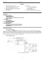
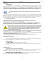
Pulsar PSDC04122T - v1.0 is a stabilized power supply unit designed for supplying CCTV devices requiring stabilized voltage of 12V DC. Its 4 outputs are protected independently by glass fuses and feature individual LED indication. The unit offers voltage adjustment within the range of 12.0V÷15.0V DC and includes protection systems against short-circuit, overload, overvoltage, and surges.
Pulsar PSDC04122T - v1.0 is a stabilized power supply unit designed for supplying CCTV devices requiring stabilized voltage of 12V DC. Its 4 outputs are protected independently by glass fuses and feature individual LED indication. The unit offers voltage adjustment within the range of 12.0V÷15.0V DC and includes protection systems against short-circuit, overload, overvoltage, and surges.


-
 1
1
-
 2
2
-
 3
3
-
 4
4
-
 5
5
-
 6
6


Pulsar PSDC04122T - v1.0 Operating instructions
- Type
- Operating instructions
Pulsar PSDC04122T - v1.0 is a stabilized power supply unit designed for supplying CCTV devices requiring stabilized voltage of 12V DC. Its 4 outputs are protected independently by glass fuses and feature individual LED indication. The unit offers voltage adjustment within the range of 12.0V÷15.0V DC and includes protection systems against short-circuit, overload, overvoltage, and surges.
Ask a question and I''ll find the answer in the document
Finding information in a document is now easier with AI
Related papers
-
Pulsar PSDC04122T - v1.0 Operating instructions
-
Pulsar PSDC04122T Operating instructions
-
-
-
-
-
-
-
-
