Page is loading ...

LUNKENHEIMER EXTERNAL DISC VALVES
Figure K4100/K4150
Installation, operation and maintenance instructions
© 2017 Emerson. All Rights Reserved.Emerson.com/FinalControl VCIOM-04555-EN 18/06
WARNING
For Safety reasons, it is important to take the
following precautions before working on the valve:
1. SLURRY VALVES ARE NOT TO BE USED AS AN
END OF LINE SERVICE VALVE.
2. Ensure that the procedures below meet or
agree with the site procedures if not review
with your site safety officers.
3. Personnel making any adjustments to the
valve should utilize equipment and clothing
normally used to work with the process where
the valve is to be installed.
4. The line must be depressurized, drained and
vented before installing or working on the
valve.
5. Handling and installation of all valves,
operators and actuators must be carried
out by personnel trained in all aspects of
installation and manual/mechanical handling
techniques using site occupational health
and safety procedures.
6. Ensure the valve pressure/temperature
limitations marked on the nameplate are
above or equal to the service conditions.
7. IF UNSURE PLEASE ASK FOR ADVICE.
1 STORAGE INSTRUCTIONS
The valves discs, seats, stems and end
connections should be adequately protected
against damage. The protective end covers
should not be removed until ready for
installation.
For long term storage of Lunkenheimer valves
the manufacturer would recommend the
following procedures be adopted:
Protection
The internals of valve are to be sprayed with a
moisture exclusion/corrosion inhibitor material.
To achieve this, wearing the correct personal
protection equipment and clothing, remove
inlet end covers and open valve by rotating
wrench and direct the atomized spray mist into
the open valve cavity. Spray around seat and
disc and close valve. Spray onto stem and yoke
bush. Reseal the end covers.
2 PIPE COMPATIBILITY
Lunkenheimer valves are suitable for
installation into most piping systems. The
standard end connections are Flanged ASME
Class 150 and PN10. Other end connections
are available upon request.
3 SELECTION
Ensure the valve’s materials of construction
and pressure/temperature limits shown on
the nameplate are suitable for the process
fluid and conditions. If in doubt contact the
manufacturer.
Operation
Valves are to be cycled every three months. The
cycle operation should be to the full open then
to the full closed position.
Storage
All valves should be stored in the fully closed
position end protection caps or covers should
remain on the valve at all times.

2
LUNKENHEIMER EXTERNAL DISC VALVES
Figure K4100/K4150
4 NAME PLATES
PED PLATE (FOR PED VALVES ONLY)
SMALL IDENTIFICATION PLATE (NPS 2 – 12 (DN 50 - 300))
LARGE IDENTIFICATION PLATE (NPS 14 – 20 (DN 350 - 500))
CE authorization number CE serial number
Minimum temperature
Lunkenheimer part number Design specification
Country of origin
Valve temperature/pressure rating
Factory reference number
Body, stem, disc
and seat materials
NOTE
Data filled is typical only.

3
5
1
9
13
3
7
11
15
2
6
10
14
4
12
16
8
LUNKENHEIMER EXTERNAL DISC VALVES
Figure K4100/K4150
5 UNPACKING
Valves are shipped on pallets or sealed wooden
frame cases. Protective end coverings should
remain on the valves until ready for installation.
On receipt, all valves should be inspected for
loose or damaged parts and, if necessary,
claims promptly submitted to the point of
purchase.
6 SAFETY PRECAUTIONS
Whenever a valve is being installed or removed
from the pipeline, ensure the line is not
pressurized and any hazardous fluid is drained
away.
Cycle the valve to ensure there is no extraneous
media in cavity area and leave in the open
position. Check that the seat and body pressure
ratings are suitable for the service prior
to installation. These ratings must not be
exceeded.
CAUTION
Valve may contain hot fluid and may result in
valve surface being hot to touch.
7 GENERAL
The preferred direction of flow for K4100
and K4150 Lunkenheimer valves is from the
lower port below the disc, exiting from the
side port. Gaskets are required to fit between
valve flanges and pipeline. Check gaskets are
suitable for duty.
8 LINE INSTALLATION
Caution should be exercised to prevent
damage of the valve sealing mechanism during
installation. The following steps will assist
in complying with the correct installation
procedure.
Remove the protective end covers prior to
installation. The gasket faces should be wiped
with clean solvent to ensure gasket faces are
clean.
Ensure that the flange facings are clean and
undamaged. No visual defects (scratches/
impacts, etc) is tolerated on flange facings as
minor defects in contact with critical fluids
could induce rapid corrosion and leakage to
atmosphere.
Substantial supports should be provided for
the free ends of the pipeline and for the valve
during installation. Unsupported pipelines hung
from valves can cause high stress in valve body
leading to possible damage.
For valves where the mating component has
been removed from the remainder of the valve,
the disc should be in the closed position before
refitting to the installed mating component.
This will allow the disc to hold the seat in the
correct position to ensure the valve will seal
after refitting the mating component.
Where possible, leave valve in `open’ position
until entire construction work has been
completed, pipeline cleaned and plant is ready
for startup.
9 FLANGED VALVES
Fit gaskets of suitable material, place in
position on the flanges, install bolts and run
up nuts. Tighten flange nuts to correct torque
(see chart page 3) using suitable wrenches and
working diagonally opposite nuts in sequence
around the periphery.
NOTE
Typical flange showing tightening sequence.
FLANGE TIGHTENING SEQUENCE
10 TESTING INSTALLATIONS
When pipeline or vessel installations are being
tested it is desirable to have all Valves in the
`open’ position. DO NOT USE Lunkenheimer
Valves as Block Valves when testing pipelines
or vessels as foreign matter may seriously
damage sealing mechanism. Should valves
be used for such testing, the Manufacturer
takes NO RESPONSIBILITY for any damage
which may affect the valves sealing mechanism
and all Guarantees are withdrawn. If the user
decides to test such installations with the
valves `closed’, caution should be exercised
to ensure that the sealing mechanism is not
subjected to pressure differentials in excess of
the maximum operating pressure of the valve
seat design.

4
100
110
120
130
150
200
210
230
236
400
500
700
705
121
131
965
O
S
430
100
110
120
130
150
200
210
230
236
400
500
700
705
121
131
965
O
S
430
LUNKENHEIMER EXTERNAL DISC VALVES
Figure K4100/K4150
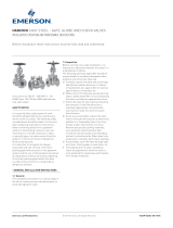
11 OPERATING INSTRUCTIONS
MATERIALS (FIGURE K4100)
Item Description
100 Body
110 Seat
120 Gasket-yoke
121 Gasket-seat
130 Studs/nuts-yoke
131 Studs/nuts-mating component
150 Mating component
200 Yoke
210 Packing
230 Packing gland
236 Spring washer-eyebolts
400 Stem
430 Stem guide
500 Disc
700 Handwheel
705 Protection hood
965 Tag plate
Operation of Lunkenheimer valves utilize the
following items:
700 Handwheel
430 Stem guide
To open and close valve
1. Rotate the Handwheel (700) to open and
close valve. Clockwise rotation of the
Handwheel closes the valve.
2. Note that the Position of the Stem Guide
(430) against the Yoke will indicate an
approximate position of the disc.
FIGURE K4100
FIGURE K4150
MATERIALS (FIGURE K4150)
Item Description
100 Body
110 Seat
120 Gasket-yoke
121 Gasket-seat
130 Studs/nuts- yoke
131 Studs/nuts- mating component
150 Mating component
200 Yoke
210 Packing
230 Packing gland
236 Spring washer-eyebolts
400 Stem
430 Stem guide
500 Disc
700 Handwheel
705 Protection hood
965 Tag plate

5
M10 25 34 M10 17 23
M12 43 58 M12 29 39
M14 70 95 M14 47 64
M16 106 144 M16 71 96
M18 151 205 M18 101 137
M20 216 293 M20 144 195
1” - UNC 477 647 1” - UNC 318 431
LUNKENHEIMER EXTERNAL DISC VALVES
Figure K4100/K4150
12 REGULAR MAINTENANCE
1. ENSURE CORRECT PROTECTIVE CLOTHING
AND EQUIPMENT IS WORN AT EACH
INSTALLATION.
2. Ensure that periodic inspection of the
internal body and parts for possible erosion
and corrosion damage is made.
3. Ensure threads and bearings are kept free
from dirt and lubricated regularly. Grease
nipples are provided to assist with bearing
lubrication.
4. The gland packing will require regular
tensioning to ensure that the gland remains
tight. Ensure that each gland nut is
tensioned an equal amount so that gland is
pulled down evenly. Do not over tighten; as
this will cause difficult operation of the valve
and premature gland wear.
Note: see page 6 ‘GLAND EYEBOLT
TORQUES’ for recommended torque values.
BOLT TORQUES FOR BOTH LUBRICATED AND TEFLON COATED BOLTS
Lubricated B7/2H, L7/GR4 PTFE COATED B7/2H, L7/GR4, B16/GR4
Stud size Torque Stud size Torque
(inches) lb·ft Nm (inches) lb·ft Nm
NOTES
Above torques are based on B7/2H, L7/GR4 and B16/
GR4 Stud Bolts/Nuts only to produce 60% of yield
stress.
Please contact Emerson or their agents prior to using
the above Torque values on Stud Bolts other than B7
and B16.
5. After prolonged valve usage the gland
packing will need to be replaced. The
following steps need to be followed:
a. Open valve, ensure pressure is removed
from line and fluid is drained. Emerson
does not recommend repacking with the
line under pressure, as scale build up will
often prevent back seating of stem.
b. Undo the two gland nuts.
c. Remove the disc springs and Belleville
washers.
d. Lift gland and remove all old packing
from stuffing box.
e. Replace packing with correct size and
style packing for the duty. Check with
Emerson or their agent for spares
recommendations. Insert one ring at a
time and compact into position.
f. When all rings are positioned and
compressed, position gland and refit
Belleville washers, tighten gland nuts to
the correct tension. Note care should be
taken to ensure both nuts are tightened
evenly.

6
2 50 1.0 1.4
3 80 1.8 2.4
4 100 1.5 2.0
5 125 2.7 3.6
6 150 2.7 3.6
8 200 4.1 5.6
10 250 9.0 12.2
12 300 5.8 7.9
14 350 7.0 9.5
16 400 11.1 15.1
18 450 13.7 18.6
20 500 16.7 22.6
LUNKENHEIMER EXTERNAL DISC VALVES
Figure K4100/K4150
GLAND EYEBOLT TORQUES
Size Eyebolt / T-Bolt Torque
NPS DN ft·lb Nm
WARNING
Do not over tighten gland nuts, as this will cause
difficult operation of the valve and premature
gland wear.
Neither Emerson, Emerson Automation Solutions, nor any of their affiliated entities assumes responsibility for the selection, use or maintenance of any product.
Responsibility for proper selection, use, and maintenance of any product remains solely with the purchaser and end user.
Emerson Automation Solutions, Emerson andthe Emerson logo are trademarks and service marks of Emerson Electric Co. All other marks are the property of their
respective owners.
The contents of this publication are presented for informational purposes only, and while every effort has been made to ensure their accuracy, they are not to be
construed as warranties or guarantees, express or implied, regarding the products or services described herein or their use or applicability. All sales are governed by
our terms and conditions, which are available upon request. We reserve the right to modify or improve the designs or specifications of such products at any time without
notice.
Emerson.com/FinalControl
/