Page is loading ...

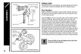
Chain length
If the rear derailleur is a GS type
Add 2 links (with the chain on both the largest sprocket
and the largest chainring)
Chain
Large chainringLargest sprocket
Tightening torque:
3 - 4 Nm
{26 - 34 in. lbs.}
Installation of the rear derailleur
Adapter type (GS)
Frame
Bracket bolt
Bracket
Bracket nut
Installation of the freewheel
To install
To
disassemble
Freewheel removal tool
TL-FW30
Tightening torque:
30 Nm {260 in. lbs.}
Notes:
• Because the high cable resistance of a frame with internal
cable routing would impair the SIS function, this type of
frame should not be used.
• For smooth operation, use the specified outer casing and
the bottom bracket cable guide.
• For maximum performance we highly recommend Shimano
lubricants and maintenance products.
• To ensure the best performance, be sure to use only the
specified type of chain. The wide type chain cannot be
used.
Installation of the bottom bracket
Tightening torque:
50 - 70 Nm
{435 - 608 in. lbs.}
Install using the special tool TL-UN73.
First install the main body, then the adapter.
S
H
I
M
A
N
O
S
G
E
-
3
0
S
H
I
M
A
N
O
S
G
E
-
4
0
S
G
C
h
a
i
n
o
n
l
y
F
o
r
N
A
R
R
O
W
Tightening torque:
35 - 50 Nm
{305 - 435 in. lbs.}
Securely tighten
Installation of the front chainwheel
1. Use the cotterless crank
extractor (TL-FC10) to install
the front chainwheel.
Installation of the front derailleur
1. Install so that there is 1 -3 mm of clearance at the closest
point between
the largest
chainring and
the bottom edge
of the chain
guide.
2. The level section of the chain guide outer plate should
be directly above and parallel to the largest chainring.
3. Secure using a 9mm spanner.
Tightening torque:
5 - 7 Nm
{44 - 60 in. lbs.}
Chain guide
Chainwheel
(largest chainring)
SIS Adjustment
1
2
Guide pulley
Largest sprocket
1
2
Guide pulley
Outer side of
smallest sprocket
Pull
Groove
Note: Be sure that the cable is
securely in the groove.
3. Low adjustment
Turn the low adjustment screw so that the guide pulley moves to a
position directly below the
largest sprocket.
1
2
Low
adjustment
screw
Stroke adjustment and cable securing
1. Top adjustment
Turn the top adjustment screw to adjust so that the guide pulley is
below the outer line of the smallest sprocket when looking from the rear.
1
2
Top
adjustment
screw
2. Connection and securing of cable
Connect the cable to the rear derailleur and, after taking up the initial
slack in the cable, reattach to the rear derailleur as shown in the
illustration.
Secure the cable by pulling it with pliers with a force of 5-10 kg.
Tightening torque:
5 - 7 Nm {44 - 60 in. lbs.}
Mounting the shifting lever
Lever mounting bolts
NOTE:
To mount the shifting
lever in a top-mount
position, install it so
that it cannot touch the
brake lever.
Do not allow them to touch each other.
Shifting lever
Brake lever body
Tightening torque:
2.5 Nm {21 in. lbs.}
Be sure to follow the sequence described below.
1. Low adjustment
Set so that the clearance between the chain guide
inner plate and the chain is 0-0.5mm.
Tension adjustment of the front
shifting cable
Chain guide
inner plate
Chain
Low
adjustment
screw
Chain position
Largest
sprocket
Smallest
chainring
2. While pulling the inner cable, tighten the wire fixing
bolt with a 5 mm allen key to secure the cable.
Tightening torque:
5 - 7 Nm {44 - 60 in. lbs.}
After taking up the initial slack
in the cable, re-secure to the
front derailleur as shown in the
illustration.
Pull
3. Top adjustment
Set so that the clearance
between the chain guide
outer plate and the chain is
0-0.5 mm.
Smallest
sprocket
Largest
chainring
Chain guide
outer plate
Top adjustment
screw
Chain
Chain position
GS
SL-TY18
Before use, read these instructions carefully, and follow them for correct use.
BB-TY30
CN-UG50 / CN-HP20
SM-SP18
FD-TY18
SIS 40
FC-TY30 / FC-TY33
SL-TY18
Bottom bracket
MF-ZH06
Multiple freewheel
Chain
Bottom bracket cable guide
Shifting lever
Front chainwheel
RD-TY18
Rear derailleur
Outer casing
Front derailleur
In order to realize the best performance, we recommend that the following
combination be used.
Thread
dimensions
BC1.37 X 24 T.P.I
.
M36 X 24 T.P.I.
BC1.37" X 24 T.P.I.
Type
Triple
Spindle
length
122.5
mm
Chain line
47.5mm
Shell
width
68
70
73
Stamped
marking
D-NL
D-NL
D-NL
Model number Sprockets Type
SL-TY18
F Triple
Thumb shifter
R 6-speed
Shifting lever
Specifications
A'
A
Stroke
(A-A')
Chainstay
angle
Bottom Bracket
Speeds
Total capacity
Rear largest sprocket
Rear smallest sprocket
28T (Triple front chainwheel)
14T
Rear derailleur
Sprockets
Tooth combination
6-speed
14, 16,18, 21, 24, 28T
Sprocket tooth configurations
SI-6D80B
SERVICE INSTRUCTIONS
Normal type
28.6 mm
38 - 54
66 - 69
Type
Front derailleur
installation band diameter
Stroke (A-A')
Chainstay angle ( )
Front Derailleur
Steel
48T-38T-28T
160 mm / 170 mm
BC 9/16" X 20 T.P.I. (English thread)
BC 1.37" X 24 T.P.I. (68, 73 mm),
M36 X 24 T.P.I. (70 mm)
Material
Front chainwheel tooth
combination
Crank arm length
Pedal thread dimensions
Bottom bracket cup
thread dimensions
Front chainwheel
Please note: specifications are subject to change for improvement without notice. (English)
© Nov. 2000 by Shimano Inc. XBC SZK Printed in China
One Holland Irvine CA 92618 U.S.A. Phone 949-951-5003
®
Industrieweg 24 NL-8071 CT Nunspeet Holland Phone 31-341-272222
77
Oimatsu-cho
3
-cho Sakai Osaka
590
-
8577
Japan Phone
072
-
223
-
3243
Type
6-speed
34T
Lever unit
DO NOT DISASSEMBLE
the shifting lever.
4. Troubleshooting chart
After completion of steps 1 - 3, move the shifting
lever to check the shifting. (This also applies if
shifting becomes difficult during use.)
Tighten the top
adjustment screw
clockwise
(about 1/4 turn).
Loosen the top
adjustment screw
counterclockwise
(about 1/8 turn).
Loosen the low
adjustment screw
counterclockwise
(about 1/4 turn).
Tighten the top
adjustment screw
clockwise
(about 1/8 turn).
Loosen the top
adjustment screw
counterclockwise
(about 1/8 turn).
Tighten the low
adjustment screw
clockwise
(about 1/2 turn).
If the chain falls to the
crank side
If shifting is difficult
from the intermediate
chainring to the largest
chainring
If shifting is difficult
from the intermediate
chainring to the
smallest chainring
If there is interference
between the chain and
the front derailleur
inner plate at the
largest chainring
If there is interference
between the chain and
the front derailleur
outer plate at the
largest chainring
If the chain falls to the
bottom bracket side.
1. Operate the shifting lever to move the
chain from the top gear to the 2nd gear.
* If the chain will not move to the 2nd
gear, turn the outer casing adjustment
barrel to increase the tension-----
①
(counter clockwise)
* If the chain moves past the 2nd
gear,decrease the tension---
➁
(clockwise)
3rd 2nd Top
Outer casing
adjustment
barrel
①
➁
2. Next with the chain on the 2nd gear,
increase the inner cable tension
①
while turning the crank forward. Stop
turning the cable adjusting barrel just
before the chain makes noise
against the 3rd gear.
This completes the adjustment.
Counter-
clockwise
①
Clockwise
➁
Outer casing
adjustment barrel
For the best SIS performance, periodically lubricate all power-
transmission parts.
Front Chainwheel
Bottom BracketAdapter
• If it is necessary to adjust the length of the chain due to a change in the number
of sprocket teeth, make the cut at some other place than the place where the
chain has been joined using a reinforced connecting pin or an end pin. The chain
will be damaged if it is cut at a place where it has been joined with a reinforced
connecting pin or an end pin.
WARNING
• Use neutral detergent to clean the chain. Do not use alkali-based or acid based
detergent such as rust cleaners as it may result in damage and/or failure of the
chain.
• Use the reinforced connecting pin only for connecting the narrow type of chain.
• There are two different types of reinforced connecting pin available. Be sure to
check the table below before selecting which pin to use. If connecting pins other
than reinforced connecting pins are used, or if a reinforced connecting pin or tool
which is not suitable for the type of chain is used, sufficient connection force may
not be obtained, which could cause the chain to break or fall off.
• Obtain, read and carefully service instructions when installing parts. A loose,
worn, or damaged parts may cause injury to the rider.
We strongly recommend that only genuine Shimano replacement parts be used.
D
U
R
A
-
A
C
E
Reinforced
Connecting Pin
Link PinEnd Pin
Chain toolChain
9-speed super narrow chain
such as
CN-7700 / CN-HG92
8- / 7- / 6-speed narrow
chain such as
CN-HG50 / CN-IG51
Reinforced
connecting pin
TL-CN31/TL-CN22
TL-CN31/TL-CN22 and
TL-CN30/TL-CN21
6.5mm
7.1mm
Silver
Black
1 - 3 mm
This service instruction explains how to use and maintain the Shimano bicycle
parts which have been used on your new bicycle.
For any questions regarding your bicycle or other matters which are not related to
Shimano parts, please contact the place of purchase or the bicycle manufacturer.
/