FORWARD
R
1
2
1 mm 1 mm
1
2
1
2
1 mm
FORWARD
R
FORWARD
R
FORWARD
R
A
4 mm Allen key
BL-M970
SI-8E40A
Multi-Condition
Brake System
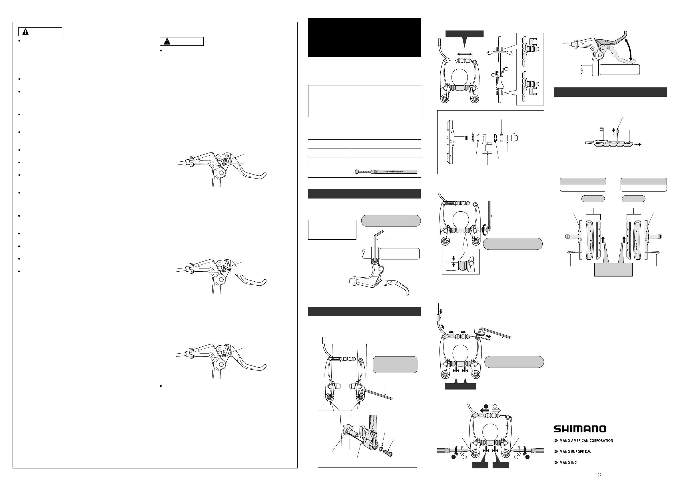
The M970 brake system is equipped with a pitch adjusting screw in
the wire hooking unit of the BL-M970 brake lever which allows the
rider to change the relationship between the brake input and output.
If the pitch adjustment screw is turned clockwise, the braking force
will be dramatically increased, so that a high level of braking
performance can be achieved from only a small amount of lever
movement. Accordingly, normal braking operation may cause a
greater-than-expected amount of braking force to be applied, which
could make the bicycle fall forward, causing serious injury to the
rider. To avoid this, please read the following instructions thoroughly
before turning the pitch adjusting screw clockwise.
After removing the pitch fixing block, make sure that you
are completely used to the new braking characteristics
before riding the bicycle, otherwise the bicycle might fall
forward if you have to apply the brakes suddenly, such as
when a vehicle appears.
With the pitch fixing block in place (standard
specifications for shipment)
1)
An ample degree of braking force can be obtained from an even
smaller amount of brake lever input than in 2) above, to provide
the highest level of brake performance.
However, because the braking force is even more sensitive to
the amount of lever input than in 2), be sure to practice using the
brakes as described above. Beginners or those who are not fully
confident should not use the brakes in this configuration.
An ample degree of braking force can be obtained from a small
amount of brake lever input, to provide a high level of brake
performance. However, if the brakes are operated suddenly,
there is the danger that the bicycle may fall forward. After
removing the pitch fixing block and turning the pitch adjusting
screw clockwise, first ride the bicycle at a speed of less than
6 mph (10 km/h) while applying the brakes repeatedly in order to
get a feel for the difference in braking characteristics before
riding at higher speeds. Beginners should be particularly careful.
2)
3)
Pitch adjusting screw
Pitch adjusting screw
Pitch adjusting screw
Pitch fixing block
With the pitch fixing block removed and the pitch
adjusting screw tightened to the position in the
illustration
With the pitch adjusting screw fully tightened
Center
May 2006 by Shimano Inc. PIT. IZM. Printed in Japan
C
General Safety Information
– To avoid serious injuries:
Improper use of your bicycle's brake system may result in a loss of
control or an accident, which could lead to a severe injury. Because
each bicycle may handle differently, be sure to learn the proper
braking technique (including brake lever pressure and bicycle
control characteristics) for your bicycle.
Consult your bicycle dealer and the bicycle's owners manual, and
practice your riding and braking technique.
Brakes designed for use as rear brakes should not be used as front
brakes.
Obtain and read the service instructions carefully prior to installing
the parts. Loose, worn, or damaged parts may cause serious injury
to the rider. We strongly recommend only using genuine Shimano
replacement parts.
Be careful not to allow any oil or grease to get onto the brake shoes.
If any oil or grease do get on the shoes, you should replace the
shoes, otherwise the brakes may not work correctly.
Check the brake cable for rust and fraying, and replace the cable
immediately if any such problems are found. If this is not done, the
brakes may not work correctly.
Always make sure that the front and rear brakes are working
correctly before you ride the bicycle.
The required braking distance will be longer during wet weather.
Reduce your speed and apply the brakes early and gently.
If the road surface is wet, the tires will skid more easily. If the tires
skid, you may fall off the bicycle. To avoid this, reduce your speed
and apply the brakes early and gently.
Read these Technical Service Instructions carefully, and keep them
in a safe place for later reference.
WARNING
Shimano BR-M970 Safety Information
– To avoid serious injuries:
WARNING
Use the BR-M970 V-BRAKE brake with SERVO WAVE
ACTION and adjustable V-BRAKE brake-compatible
levers such as the BL-M970 brake levers.
The optimum efficiency of the Multi-Condition Brake System can be
realized by using the brakes and brake levers in the recommended
set.
If the brake shoes have worn down until the grooves are no longer
visible, they should be replaced.
Parts are not guaranteed against natural wear or deterioration
resulting from normal use.
For maximum performance we highly recommend Shimano
lubricants and maintenance products.
For any questions regarding methods of handling or maintenance,
please contact the place of purchase.
NOTE:
Replacement of the cartridge shoe
Remove the shoe fixing pin, and then slide the shoe along
the groove to remove it from the shoe holder.
1.
There are two different types of shoe and shoe holder to
be used in the left and right positions respectively. Slide
the new shoes into the grooves on the shoe holders while
taking note of the correct directions and pin hole positions.
2.
Insertion of shoe fixing pin is very critical to keep shoe
properly fixed in place.
3.
39 mm or more
Washer A
Washer A
Shoe fixing link
Shoe fixing nut
Washer
While holding the shoe against the rim, adjust the amount
of shoe protrusion by changing over the washer B (thick or
thin) so that dimension A is kept at 39 mm or more.
Washer B (thin)
Washer B (thick)
2.
Depress the brake lever about 10 times as far as the grip
and check that everything is operating correctly and that
the shoe clearance is correct before using the brakes.
6.
3.
4.
5.
5 mm Allen key
Inner cable lead
5 mm Allen key
Tightening torque:
6 – 8 N·m {52 – 69 in. lbs.}
Tightening torque:
6 – 8 N·m {52 – 69 in. lbs.}
Adjust the balance with the spring tension adjustment
screws.
Depress about
10 times
Shoe fixing pin
Shoe
ShoeShoe
Shoe holderShoe holder
Shoe fixing pinShoe fixing pin
Same at front and rear
For the left
Same at front and rear
For the right
These service instructions are printed on recycled paper.
Please note: Specifications are subject to change for improvement without
notice. (English)
Technical Service Instructions
Multi-Condition Brake System
By providing superior wet weather braking performance
(control and modulation), braking performance will not
vary in a multitude of conditions when using this brake
system.
Installation of the brake lever
Use a 4 mm Allen key to install the brake lever. Insert the 4
mm Allen key so that it goes as far into the head of the bolt as
possible at this time.
Installation of the V-BRAKE brake
In order to realize the best performance, we recommend that
the following combination be used.
XTR
BL-M970
BR-M970
Brake lever
Series
V-BRAKE brake
Brake cable
Insert the stopper pin of the brake body into the center
spring hole in the frame mounting boss, and then secure
the brake body to the frame with the link fixing bolt.
1.
Use a handlebar grip
with a maximum outer
diameter of 32 mm.
Spring hole
Stopper pin
Link fixing bolt
Washer
5 mm Allen key
Tightening torque:
5 – 7 N·m
{43 – 61 in. lbs.}
Pass the inner cable through the inner cable lead, and
after setting so that the total of the clearances between the
left and right shoes and the rim is 2 mm, tighten the cable
fixing bolt.
While holding the shoe against the rim, tighten the shoe
fixing nut.
Front Front
Tightening torque:
6 – 8 N·m {52 – 69 in. lbs.}
In the case of carbon
handlebars, it may be
necessary to lower the
tightening torque in order to
prevent damage to the
handlebar. Please consult
the bicycle or handlebar
manufacturer
regarding the
appropriate level of
tightening torque for
carbon handlebars.
B C
B
+
C
=
2 mm
Spring tension
adjustment screw
Spring tension
adjustment screw
FORWARD
FORWARD
R
R
FORWARD
FORWARD
L
L
Shoe insertion
direction
One Holland, Irvine, California 92618, U.S.A. Phone: +1-949-951-5003
Industrieweg 24, 8071 CT Nunspeet, The Netherlands Phone: +31-341-272222
3-77 Oimatsu-cho, Sakai-ku, Sakai, Osaka 590-8577, Japan

