
OPERATOR’S MANUAL
MANUEL D’UTILISATION
MANUAL DEL OPERADOR
PLUNGE BASE ROUTER
VARIABLE SPEED / DOUBLE INSULATED
DÉFONCEUSE À BASE PLONGEANTE
VITESSE VARIABLE / DOUBLE ISOLATION
FRESADORA DE BASE TIPO ÉMBOLO
VELOCIDAD VARIABLE / DOBLE AISLAMIENTO
RE180PL1 / RE180PL1G
WARNING: To reduce the
risk of injury, the user must read and
understand the operator’s manual before
using this product.
SAVE THIS MANUAL FOR
FUTURE REFERENCE
ADVERTENCIA: Para
reducir el riesgo de lesiones, el usuario
debe leer y comprender el manual del
operador antes de usar este producto.
AVERTISSEMENT :
Pour
réduire les risques de blessures,
l’utilisateur doit lire et veiller à bien
comprendre le manuel d’utilisation avant
d’employer ce produit.
GUARDE ESTE MANUAL
PARA FUTURAS CONSULTAS
CONSERVER CE MANUEL
POUR FUTURE RÉFÉRENCE
TABLE OF CONTENTS
****************
General Power Tool Safety
Warnings
.........................................2-3
Router Safety Warnings .....................3
Symbols
..............................................4
Electrical
............................................. 5
Features
..............................................6
Assembly ............................................ 6
Operation .......................................6-12
Adjustments .....................................12
Maintenance ..................................... 13
Illustrations ..................................15-17
Parts Ordering and
Service
................................Back page
TABLE DES MATIÈRES
****************
Règles de sécurité relatives
aux outils électriques
......................2-3
Avertissements de sécurité
relatifs au toupie
.................................3
Symboles
............................................4
Caractéristiques électriques
...............5
Caractéristiques
.................................6
Assemblage ........................................6
Utilisation ......................................6-12
Réglages ...........................................12
Entretien ...........................................13
Illustrations ..................................15-17
Commande de pièces
et dépannage
....................Page arrière
ÍNDICE DE CONTENIDO
****************
Advertencias de seguridad
para herramientas eléctricas
......... 2-3
Advertencias de seguridad
fresadora
............................................3
Símbolos
............................................4
Aspectos eléctricos
...........................5
Características ...................................6
Armado ..............................................6
Funcionamiento ........................... 6-12
Ajustes .............................................12
Mantenimiento .................................13
Illustraciones .............................. 15-17
Pedidos de piezas
y servicio
.......................Pág. posterior

2 − English
GENERAL POWER TOOL SAFETY WARNINGS
WARNING
Read all safety warnings and all instructions. Failure to
follow the warnings and instructions may result in electric
shock, fire and/or serious injury.
Save all warnings and instructions for future reference.
The term “power tool” in the warnings refers to your mains-
operated (corded) power tool or battery-operated (cordless)
power tool.
WORK AREA SAFETY
Keep work area clean and well lit. Cluttered or dark
areas invite accidents.
Do not operate power tools in explosive atmospheres,
such as in the presence of flammable liquids, gases
or dust. Power tools create sparks which may ignite the
dust or fumes.
Keep children and bystanders away while operating a
power tool. Distractions can cause you to lose control.
ELECTRICAL SAFETY
Power tool plugs must match the outlet. Never modify
the plug in any way. Do not use any adapter plugs with
earthed (grounded) power tools. Unmodified plugs and
matching outlets will reduce risk of electric shock.
Avoid body contact with earthed or grounded surfaces
such as pipes, radiators, ranges and refrigerators.
There is an increased risk of electric shock if your body
is earthed or grounded.
Do not expose power tools to rain or wet conditions.
Water entering a power tool will increase the risk of electric
shock.
Do not abuse the cord. Never use the cord for carrying,
pulling or unplugging the power tool. Keep cord away
from heat, oil, sharp edges or moving parts. Damaged
or entangled cords increase the risk of electric shock.
When operating a power tool outdoors, use an exten-
sion cord suitable for outdoor use. Use of a cord suitable
for outdoor use reduces the risk of electric shock.
If operating a power tool in a damp location is unavoid-
able, use a ground fault circuit interrupter (GFCI) pro-
tected supply. Use of a GFCI reduces the risk of electric
shock.
PERSONAL SAFETY
Stay alert, watch what you are doing and use com-
mon sense when operating a power tool. Do not use
a power tool while you are tired or under the influence
of drugs, alcohol or medication. A moment of inattention
while operating power tools may result in serious personal
injury.
Use personal protective equipment. Always wear eye
protection. Protective equipment such as dust mask, non-
skid safety shoes, hard hat, or hearing protection used for
appropriate conditions will reduce personal injuries.
Prevent unintentional starting. Ensure the switch is in
the off-position before connecting to power source
and/or battery pack, picking up or carrying the tool.
Carrying power tools with your finger on the switch or
energising power tools that have the switch on invites
accidents.
Remove any adjusting key or wrench before turning
the power tool on. A wrench or a key left attached to a
rotating part of the power tool may result in personal injury.
Do not overreach. Keep proper footing and balance at
all times. This enables better control of the power tool in
unexpected situations.
Dress properly. Do not wear loose clothing or jewellery.
Keep your hair, clothing and gloves away from moving
parts. Loose clothes, jewellery or long hair can be caught
in moving parts.
If devices are provided for the connection of dust
extraction and collection facilities, ensure these are
connected and properly used. Use of dust collection
can reduce dust-related hazards.
Do not wear loose clothing or jewelry. Contain long
hair. Loose clothes, jewelry, or long hair can be drawn
into air vents.
Do not use on a ladder or unstable support. Stable
footing on a solid surface enables better control of the
power tool in unexpected situations.
POWER TOOL USE AND CARE
Do not force the power tool. Use the correct power
tool for your application. The correct power tool will
do the job better and safer at the rate for which it was
designed.
Do not use the power tool if the switch does not turn
it on and off. Any power tool that cannot be controlled
with the switch is dangerous and must be repaired.
Disconnect the plug from the power source and/or
the battery pack from the power tool before making
any adjustments, changing accessories, or storing
power tools. Such preventive safety measures reduce
the risk of starting the power tool accidentally.
Store idle power tools out of the reach of children and
do not allow persons unfamiliar with the power tool
or these instructions to operate the power tool. Power
tools are dangerous in the hands of untrained users.
Maintain power tools. Check for misalignment or bind-
ing of moving parts, breakage of parts and any other
condition that may affect the power tool’s operation.
If damaged, have the power tool repaired before use.
Many accidents are caused by poorly maintained power
tools.

3 − English
GENERAL POWER TOOL SAFETY WARNINGS
ROUTER SAFETY WARNINGS
Hold power tool by insulated gripping surfaces, be-
cause the cutter may contact its own cord. Cutting a
“live” wire may make exposed metal parts of the power
tool “live” and shock the operator.
Use clamps or another practical way to secure and
support the workpiece to a stable platform. Holding the
work by your hand or against the body leaves it unstable
and may lead to loss of control.
Know your power tool. Read operator’s manual care-
fully. Learn its applications and limitations, as well
as the specific potential hazards related to this tool.
Following this rule will reduce the risk of electric shock,
fire, or serious injury.
Always wear eye protection with side shields marked
to comply with ANSI Z87.1. Following this rule will re-
duce the risk of serious personal injury.
Protect your lungs. Wear a face or dust mask if the
operation is dusty. Following this rule will reduce the risk
of serious personal injury.
Protect your hearing. Wear hearing protection during
extended periods of operation. Following this rule will
reduce the risk of serious personal injury.
Inspect tool cords periodically and, if damaged, have
repaired at your nearest authorized service center.
Constantly stay aware of cord location. Following this
rule will reduce the risk of electric shock or fire.
Check damaged parts. Before further use of the
tool, a guard or other part that is damaged should
be carefully checked to determine that it will operate
properly and perform its intended function. Check for
alignment of moving parts, binding of moving parts,
breakage of parts, mounting, and any other conditions
that may affect its operation. A guard or other part that
is damaged should be properly repaired or replaced
by an authorized service center. Following this rule will
reduce the risk of shock, fire, or serious injury.
Make sure your extension cord is in good condi-
tion. When using an extension cord, be sure to use
one heavy enough to carry the current your product
will draw. A wire gauge size (A.W.G.) of at least 14 is
recommended for an extension cord 50 feet or less
in length. A cord exceeding 100 feet is not recom-
mended. If in doubt, use the next heavier gauge. The
smaller the gauge number, the heavier the cord. An
undersized cord will cause a drop in line voltage resulting
in loss of power and overheating.
Inspect for and remove all nails from lumber before
using this tool. Following this rule will reduce the risk of
serious personal injury.
If the power supply cord is damaged, it must be re-
placed only by the manufacturer or by an authorized
service center to avoid risk.
Save these instructions. Refer to them frequently and
use them to instruct others who may use this product. If
you loan someone this product, loan them these instruc-
tions also.
Keep cutting tools sharp and clean. Properly main-
tained cutting tools with sharp cutting edges are less
likely to bind and are easier to control.
Use the power tool, accessories and tool bits etc.
in accordance with these instructions, taking into
account the working conditions and the work to be
performed. Use of the power tool for operations different
from those intended could result in a hazardous situation.
SERVICE
Have your power tool serviced by a qualified repair
person using only identical replacement parts. This
will ensure that the safety of the power tool is maintained.
When servicing a power tool, use only identical re-
placement parts. Follow instructions in the Mainte-
nance section of this manual. Use of unauthorized parts
or failure to follow Maintenance instructions may create
a risk of shock or injury.

4 − English
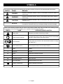
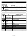
Some of the following symbols may be used on this product. Please study them and learn their meaning. Proper
interpretation of these symbols will allow you to operate the product better and safer.
SYMBOL NAME DESIGNATION/EXPLANATION
Safety Alert Indicates a potential personal injury hazard.
Read Operator’s Manual
To reduce the risk of injury, user must read and understand
operator’s manual before using this product.
Eye Protection
Always wear eye protection with side shields marked to comply
with ANSI Z87.1.
Wet Conditions Alert Do not expose to rain or use in damp locations.
V Volts Voltage
A Amperes Current
Hz Hertz Frequency (cycles per second)
min Minutes Time
Alternating Current Type of current
n
o
No Load Speed Rotational speed, at no load
Class II Construction Double-insulated construction
.../min Per Minute Revolutions, strokes, surface speed, orbits etc., per minute
The following signal words and meanings are intended to explain the levels of risk associated with this product.
SYMBOL SIGNAL MEANING
DANGER:
Indicates a hazardous situation, which, if not avoided, will result in death or
serious injury.
WARNING:
Indicates a hazardous situation, which, if not avoided, could result in death or
serious injury.
CAUTION:
Indicates a hazardous situation, that, if not avoided, may result in minor or
moderate injury.
NOTICE:
(Without Safety Alert Symbol) Indicates information considered important, but
not related to a potential injury (e.g. messages relating to property damage).
SYMBOLS

5 − English
ELECTRICAL
EXTENSION CORDS
When using a power tool at a considerable distance from
a power source, be sure to use an extension cord that has
the capacity to handle the current the tool will draw. An
undersized cord will cause a drop in line voltage, resulting in
overheating and loss of power. Use the chart to determine
the minimum wire size required in an extension cord. Only
round jacketed cords listed by Underwriter’s Laboratories
(UL) should be used.
When working outdoors with a product, use an extension
cord that is designed for outside use. This type of cord is
designated with “W-A” or “W” on the cord’s jacket.
Before using any extension cord, inspect it for loose or
exposed wires and cut or worn insulation.
**Ampere rating (on product data plate)
0-2.0 2.1-3.4 3.5-5.0 5.1-7.0 7.1-12.0 12.1-16.0
Cord Length Wire Size (A.W.G.)
25' 16 16 16 16 14 14
50' 16 16 16 14 14 12
100' 16 16 14 12 10 —
**Used on 12 gauge - 20 amp circuit.
NOTE: AWG = American Wire Gauge
WARNING:
Keep the extension cord clear of the working area.
Position the cord so that it will not get caught on lumber,
tools, or other obstructions while you are working with
a power tool. Failure to do so can result in serious per-
sonal injury.
WARNING:
Check extension cords before each use. If damaged
replace immediately. Never use product with a damaged
cord since touching the damaged area could cause elec-
trical shock resulting in serious injury.
DOUBLE INSULATION
Double insulation is a concept in safety in electric power
tools, which eliminates the need for the usual three-
wire grounded power cord. All exposed metal parts are
isolated from the internal metal motor components with
protecting insulation. Double insulated tools do not need
to be grounded.
WARNING:
The double insulated system is intended to protect the
user from shock resulting from a break in the product’s
internal insulation. Observe all normal safety precautions
to avoid electrical shock.
NOTE: Servicing of a product with double insulation requires
extreme care and knowledge of the system and should be
performed only by a qualified service technician. For service,
we suggest you return the product to your nearest authorized
service center for repair. Always use original factory replace-
ment parts when servicing.
ELECTRICAL CONNECTION
This product has a precision-built electric motor. It should
be connected to a power supply that is 120 volts, AC only
(normal household current), 60 Hz. Do not operate this
product on direct current (DC). A substantial voltage drop
will cause a loss of power and the motor will overheat. If
the product does not operate when plugged into an outlet,
double-check the power supply.

6 − English
FEATURES
PRODUCT SPECIFICATIONS
Plunge Depth ................................................................ 2 in.
Collet
......................................................................... 1/2 in.
Adaptor
...................................................................... 1/4 in.
Horsepower
....................................................................... 2
No Load Speed
..........................15,000-25,000/min (RPM)
Input
................................. 120 V, 60 Hz, AC only, 10 Amps
Net Weight
............................................................... 8.5 lbs.
ASSEMBLY
WARNING:
Do not use this product if it is not completely assembled
or if any parts appear to be missing or damaged. Use of
a product that is not properly and completely assembled
or with damaged or missing parts could result in serious
personal injury.
WARNING:
Do not attempt to modify this product or create acces-
sories or attachments not recommended for use with this
product. Any such alteration or modification is misuse
and could result in a hazardous condition leading to
possible serious personal injury.
If any parts are damaged or missing, please call 1-800-525-2579 for assistance.
OPERATION
WARNING:
Do not allow familiarity with tools to make you care-
less. Remember that a careless fraction of a second is
sufficient to inflict serious injury.
WARNING:
Always wear eye protection with side shields marked to
comply with ANSI Z87.1, along with hearing protection.
Failure to do so could result in objects being thrown into
your eyes and other possible serious injuries.
WARNING:
Do not use any attachments or accessories not
recommended by the manufacturer of this tool. The use
of attachments or accessories not recommended can
result in serious personal injury.
APPLICATIONS
You may use this tool for the purposes listed below:
Rout grooves, carve designs, mortise door jambs, and
create joints in wood and wood products
Cabinet making, routing counter tops, and finishing work
in wood and wood products

7 − English
WARNING:
Do not use bits with undersized shanks. Undersized
shanks will not tighten properly and could be thrown from
the tool causing injury.
CAUTION:
To prevent damage to the spindle or spindle lock, always
allow motor to come to a complete stop before engaging
the spindle lock.
WARNING:
If you are changing a bit immediately after use, be careful
not to touch the collet nut, bit, or collet with your hands or
fingers. You will get burned because of the heat buildup
from cutting. Always use the wrench provided.
WARNING:
If the collet nut is not securely tightened, the bit may
detach during use, causing serious personal injury.
WARNING:
Bit continues to rotate after the router has been turned off.
To avoid injury, wait until the bit has come to a complete
stop before removing router from the workpiece.
WARNING:
Do not use bits which are larger than 2-1/4 in. Never use
bits which are larger in diameter than the opening in the
router subbase. These situations could cause possible
loss of control or create other hazardous conditions that
could cause possible serious personal injury.
OPERATION
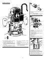
INSTALLING/REMOVING BITS
See Figures 1 - 2, page 15.
Unplug the router.
Remove chip shield from router base by pushing two
sides together and removing from base.
Depress spindle lock.
Place the wrench provided through front of router base
onto collet nut and turn counterclockwise to loosen.
Install bit once collet nut is loose. If changing bits, bit will
easily slip from collet after loosening collet nut.
Insert shank of bit until shank bottoms out, then pull it
out 1/16 in. to allow for expansion when the bit gets hot.
Tighten the collet nut securely by turning clockwise with
the wrench provided.
Release spindle lock.
Replace chip shield.
To remove the bit:
Place the wrench provided through front of router base
onto collet nut and turn counterclockwise to loosen.
Loosen the collet nut and remove the bit.
Release the spindle lock.
INSTALLING/REMOVING THE 1/4 in.
ADAPTOR
See Figures 1 - 2, page 15.
The collet is machined to precision tolerances to fit bits with
1/2 in. diameter shanks. To use bits with 1/4 in. diameter
shanks, insert the 1/4 in. adaptor into the 1/2 in. collet.
Unplug the router.
Remove chip shield from router base by pushing two
sides together and removing from base.
Depress spindle lock.
Place the wrench provided through front of router base
onto collet nut and turn counterclockwise to loosen.
Install adaptor once collet nut is loose.
Insert 1/4 in. shank bit, then tighten the collet nut securely
by turning clockwise with the wrench provided.
Release spindle lock.
Replace chip shield.
To remove the adaptor:
Place the wrench provided through front of router base
onto collet nut and turn counterclockwise to loosen.
Loosen the collet nut and remove the adaptor and bit.
Release the spindle lock.

8 − English
OPERATION
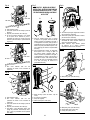
SELECTING DEPTH OF CUT
See Figures 3 - 7, pages 15 - 16.
Proper depth of cut depends on several factors: the horse-
power of the router motor, the type of bit, and the type of
wood. A lightweight, low horsepower router is designed for
making shallow cuts; a router with higher horsepower is
designed for deeper cuts. Small bits, such as veining bits
with 1/16 in. cutting diameters, are designed to remove only
small amounts of wood. Large bits, such as straight-flute
bits, remove larger amounts of wood and make deeper cuts
in soft woods, such as white pine.
Choose a depth of cut that will not place excessive strain on
the router motor. If you need extra force or the motor speed
slows down considerably, turn off the router and reduce the
depth of cut. Then, make the cut in two or more passes.
When routing a groove that is too deep to safely cut in one
pass, make the cut in several passes. We recommend that
cuts be made at a depth not exceeding 1/8 in. and that
several passes be made to reach deeper cuts.
TO ADJUST DEPTH OF CUT
See Figures 3 - 7, pages 15 - 16.
Unplug the router.
Raise bit by unlocking plunge lock lever.
Adjust hex nuts on threaded post until bit is inside router
subbase.
Place router on a flat surface.
Lower router until tip of bit barely touches flat surface.
Lock plunge lock lever to position bit at “zero” depth of
cut.
Adjust hex nuts until they come in contact with stop flange.
This will provide a position stop at “zero” depth of cut.
Make sure the hex nuts are securely tightened against
each other.
Rotate depth stop to desired position, loosen lock knob
and adjust stop bar until it touches depth stop.
Slide zero reset indicator up or down the scale on stop bar
until red line on zero reset indicator aligns with a desired
reference point. For example, align red line with 1 in. mark
on the scale.
Lift stop bar to obtain desired depth of cut. For example,
if setting 1/8 in. depth of cut, the zero reset indicator will
move 1/8 in. from the 1 in. reference point.
Tighten lock knob securely.
Position the router so that the bit can extend below the
subbase for desired depth setting.
Unlock plunge lock lever.
Grasp handles and lower router until stop bar contacts
depth stop.
Lock plunge lock lever to position bit at desired depth of
cut.
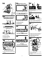
ZERO RESET INDICATOR
See Figure 5, page 16.
The zero reset indicator allows you to use the scale pro-
vided on the housing to make quick depth of cut changes
to existing depth of cut settings. Simply choose a reference
point on the scale and slide the zero reset indicator up or
down the scale the distance required for new depth of cut.
Then change stop bar position by loosening lock knob and
adjusting stop bar until red line on zero reset indicator moves
back to reference point. Tighten lock knob securely to lock
stop bar in new position. The bit position will now increase
or decrease the exact distance the stop bar was adjusted.
NOTE: Each mark on the inch scale indicates 1/16 in.
ACCU-STOP™ MICRO-ADJUSTABLE
DEPTH STOP
See Figures 6 - 7, page 16.
The ACCU-STOP™ Micro-Adjustable Depth Stop is located
on the base of your router and makes it possible to make
deep or heavy cuts in successive passes. Alignment marks
make depth of cut changes quick and easy.
A preset cutting depth is achieved by plunging router until
stop bar comes in contact with depth stop. The micro-
adjusting feature provides alignment marks at each 90° rota-
tion of the depth stop knob. Each 90° rotation of the knob
changes depth of cut setting 1/64 in.
A complete 360° rotation of the knob changes the depth of
cut setting 1/16 in.
The ACCU-STOP™ Micro-Adjustable Depth Stop provides
for depth of cut changes to be made from 0 to 1/2 in. from
the initial setting of the stop bar. This initial setting of the stop
bar can be “zero” depth of cut, or it can be any depth of cut
setting that you choose as a starting point for a particular
job to be performed.
To use the ACCU-STOP™ Micro-Adjustable Depth Stop:
Unplug the router.
Loosen lock knob and raise stop bar.
Rotate depth stop until the highest depth stop is aligned
with the stop bar.
Raise bit by unlocking plunge lock lever.
Place router on flat surface, and lower router until tip of
bit barely touches flat surface.
Lock plunge lock lever to position bit at “zero” depth of
cut.
Lower stop bar against depth stop, then tighten lock knob
securely. The highest stop now becomes the “zero” depth
of cut setting.

9 − English
OPERATION
SWITCH
See Figure 8, page 16.
The router features a soft start which allows for a gradual
increase in speed from 0 r/min. to the variable speed dial
setting. For example, if the router is set at 15,000 r/min. at
the time it is switched off and is then activated again, the
motor is designed to gradually rev up to that speed instead
of starting out at the full 15,000 r/min.
To turn the router on, push the switch to the ( I ), or ON
position. Return the switch to the ( O ), or OFF position when
routing operation is finished.
VARIABLE SPEED CONTROL SELECTOR
See Figure 9, page 16.
The router has a variable speed control selector designed
to allow operator control of speed and torque limits. You
can make speed selections best suited to the type of cut,
the material being cut, and the size of bit being used. The
variable speed control selector allows you to adjust router
speed from 15,000 to 25,000 r/min. There is a six-step scale
(A to F) on the variable speed control selector. To increase
the speed and torque of the router, turn the variable speed
control selector to a higher setting (F). Turn to a lower setting
to decrease speed and torque.
NOTE: If you do not want to use the variable speed control
selector, turn it to the highest possible setting, and the fea-
ture will not be active.
The speed selection chart shown gives suggested speed
settings based on the diameter of the bit and the type of
material being routed.
We suggest that you practice with the variable speed feature
of the router before installing a bit and making cuts in wood.
SPEED SELECTION CHART
MATERIAL
BIT SIZE
1/4 3/8 1/2 3/4
SOFT E-F D-E A-B A
MEDIUM D-E C-D A A
HARD C-D B-C A A
VERY HARD D-E C-D C-D B-C
OPERATING THE ROUTER
See Figures 10 - 11, page 16.
When routing straight cuts across a workpiece, clamp a
straight edge to the workpiece to use as a guide.
Position the straight edge parallel to the line of cut and offset
the distance between the cutting edge of the bit and the edge
of the router base. Hold the router base against the straight
edge and rout the groove.
When routing a groove wider than the diameter of the bit,
clamp a straight edge on both sides of the cut lines. Position
both guides parallel to the desired line of cut and spaced
equal distances from the desired edges of the groove. Rout
along one guide then reverse direction and rout along the
other guide. Clean out any remaining waste in the center of
the groove.
When routing a groove, the travel should be in a direction
that places the guide you are using at the right-hand side.
When the guide is positioned as shown in the “guide inside”
illustration (figure 15), tool travel should be from left to right
and counterclockwise around curves. When the guide is
positioned as shown in the “guide outside” illustration (figure
15), tool travel should be from right to left and clockwise
around curves. If there is a choice, the first setup is generally
the easier to use. In either case, the sideways thrust you use
is against the guide.
INTERNAL ROUTING
Tilt router and place on workpiece without the bit contact-
ing the workpiece.
Turn the router on and let the motor build up to full speed.
Gradually feed bit into the workpiece until the subbase
is level with the workpiece.
Upon completion of the cut, turn the router off and let the
bit come to a complete stop before removing the router
from the workpiece.

10 − English
OPERATION
EDGE ROUTING
Clamp a straight edge to the workpiece as a guide.
Place the router on the edge of the workpiece without
the bit contacting the workpiece.
Turn router on and let the motor build up to full speed.
Gradually feed the bit into the workpiece using the
clamped straight edge as a guide.
Upon completion of the cut, turn the router off and let the
bit come to a complete stop before removing the router
from the workpiece.
WARNING:
Do not use large router bits for freehand routing. Use of
large router bits when freehand routing could cause loss
of control or create other hazardous conditions that could
result in personal injury. If using a router table, large bits
should be used for edging only.
FREEHAND ROUTING
See Figure 12, page 17.
When used freehand, the router becomes a flexible and
versatile tool. This flexibility makes it possible to easily rout
signs, relief sculptures, etc. When freehand routing:
Draw or layout the pattern on the workpiece.
Choose the appropriate bit.
NOTE: A core box or V-groove bit is often used for rout-
ing letters and engraving objects. Straight bits and ball
mills are often used to make relief carvings. Veining bits
are used to carve small, intricate details.
Rout the pattern in two or more passes. Make the first
pass at 25% of the desired depth of cut. This will provide
better control as well as being a guide for the next pass.
NOTE: Do not rout deeper than 1/8 in. per pass.
EDGING WITH PILOT BIT
See Figure 13, page 17.
The arbor-type bits with pilots are excellent for quick, easy,
edge shaping of any workpiece edge that is either straight
or curved at a curvature as great or greater than the radius
of the bit to be used. The pilot prevents the bit from mak-
ing too deep a cut; and holding the pilot firmly in contact
with the workpiece edge throughout prevents the cut from
becoming too shallow.
Whenever the workpiece thickness together with the desired
depth of cut (as adjusted by router depth setting) are such
that only the top part of the edge is to be shaped (leaving
at least a 1/16 in. thick uncut portion at bottom), the pilot
can ride against the uncut portion, which serves to guide it.
However, if the workpiece is too thin or the bit set too low
so that there will be no uncut edge to ride the pilot against,
an extra board to act as a guide must be placed under the
workpiece. This “guide” board must have exactly the same
contour— straight or curved—as the workpiece edge. If it is
positioned so that its edge is flush with the workpiece edge,
the bit will make a full cut (in as far as the bit radius). On the
other hand, if the guide is positioned as shown in figure 13
(out from the workpiece edge), the bit will make less than
a full cut — which will alter the shape of the finished edge.
NOTE: Any of the piloted bits can be used without a pilot for
edge shaping with guides, as preceding. The size (diameter)
of the pilot that is used determines the maximum cut width
that can be made with the pilot against the workpiece edge
(the small pilot exposes all of the bit; the large one reduces
this amount by 1/16 in.).
DIRECTION OF FEED AND THRUST
See Figures 14 - 15, page 17.
The router motor and bit revolve in a clockwise direction. This
gives the tool a slight tendency to twist in a counterclockwise
direction, especially when the motor revs up.
Feed the router into the workpiece from left to right. When
fed from left to right, the rotation of the bit pulls the router
against the workpiece. If fed in the opposite direction, the
rotation of the spinning bit will tend to throw the router away
from the workpiece causing kickback. This could cause you
to lose control of the router.
Because of the high speed of bit rotation during a proper
feeding operation, there is very little kickback under normal
conditions. However, if the bit strikes a knot, hard grain,
or foreign object that affects the normal progress of the
cutting action, there will be a slight kickback. The direction
of kickback is always in the direction opposite bit rotation.
This will affect the trueness of the cut.

11 − English
OPERATION
To guard against kickback, plan the setup and direction of
feed so that you will always be thrusting the tool in the same
direction that the leading edge of the bit is moving. The
thrust should be in a direction that keeps the sharp edges
of the bit continuously biting straight into new (uncut) wood.
NOTE: For best results, make sure to take enough time to
set up for cutting. While cutting, make sure to use the proper
rate of feed.
PROPER RATE OF FEED
Professional routing depends upon careful setup and proper
rate of feed which is learned through practice and use. The
proper rate of feed is dependent upon:
hardness and moisture content of the workpiece
depth of cut
cutting diameter of the bit
When cutting shallow grooves in soft woods such as pine,
a faster rate of feed can be used. When making cuts in
hardwoods such as oak, a slower rate of feed is required.
Several factors will help you select the proper rate of feed.
Choose the rate that does not slow down the motor.
Choose the rate at which the bit advances firmly and
surely to produce a continuous spiral of uniform chips
or a smooth edge.
Listen to the sound of the motor. A high-pitched sound
means you are feeding too slowly. A strained, lower
pitched sound signals force feeding.
Check the progress of each cut. Too slow feeding can
cause the router to take off in a wrong direction from the
intended line of cut. Force feeding increases the strain
of holding the tool and results in loss of speed.
Notice the chips being produced as you cut. If the router
is fed too slowly, it will scorch or burn the wood. If fed
too fast, it will take large chips out of the wood and leave
gouge marks.
Test a cut on a scrap piece of the workpiece before you begin.
Always grasp and hold the router firmly with both hands.
If you are making a small diameter, shallow groove in soft,
dry wood, the proper feed rate may be determined by the
speed at which you can travel the router along the guide line.
If the bit is a large one, the cut is deep, or the workpiece is
hard to cut, the proper feed may be a very slow one. A cross
grain cut may require a slower pace than an identical with
grain cut in the same workpiece.
FEEDING TOO FAST
See Figure 16, page 17.
Clean, smooth routing and edge shaping can be done only
when the bit is revolving at a relatively high speed and is
taking very small bites to produce tiny, cleanly severed chips.
If you force the router to move forward too fast, the RPM of
the bit becomes slower than normal in relation to its forward
movement. As a result, the bit must take bigger bites as it
revolves. Bigger bites mean bigger chips and a rougher
finish. Also, because bigger bites require more power, the
router motor may become overloaded.
Under extreme force-feeding conditions, the relative RPM
of the bit can become so slow—and the bites it has to take
so large—that chips will be partially knocked off (rather
than fully cut off). This causes splintering and gouging of
the workpiece.
The router is an extremely high-speed tool, and will make
clean, smooth cuts if allowed to run freely without the overload
of a forced feed. You can always detect force feeding by the
sound of the motor. Its high-pitched whine will sound lower
and stronger as it loses speed. Also, the strain of holding
the tool will be noticeably increased.
FEEDING TOO SLOWLY
See Figure 17, page 17.
It is possible to spoil a cut by moving the router forward too
slowly. When you advance the router into the work too slowly,
the revolving bit does not dig into new wood fast enough
to take a bite; instead, it merely scrapes away sawdust-like
particles. Scraping produces heat, which can glaze, burn,
or mar the cut and in extreme cases, can overheat the bit,
destroying its hardness.
When the bit is scraping instead of cutting, controlling the
router is more difficult. With practically no load on the mo-
tor, the bit revolves at close to top RPM, and has a much
greater than normal tendency to bounce off the sides of
the cut (especially if the wood has a pronounced grain with
hard and soft areas). As a result, the cut produced may have
rippled, instead of straight, sides.
Feeding too slowly can also cause the router to take off in a
wrong direction from the intended line of cut. Always grasp
and hold the router firmly with both hands when routing.
You can detect when you are feeding the router too slowly by
the runaway, high-pitched sound of the motor or by feeling
the wiggle of the bit in the cut.

12 − English
ADJUSTMENTS
PLUNGE LOCK LEVER
See Figure 20, page 17.
After extended use, the plunge lock may wear. If this hap-
pens, you can easily adjust the lever.
Unplug the router.
WARNING:
Before performing any adjustment, make sure the tool
is unplugged from the power supply and the switch is in
the OFF ( O ) position. Failure to heed this warning could
result in serious personal injury.
Make sure lever is in locked position.
Remove the screw supporting the plunge lock lever.
Remove the lever.
Place the lever back in the original locked position.
Replace the screw.
Check for free plunge with lever rotated to unlocked
position. If router does not plunge freely, reposition
lever.
OPERATION
DEPTH OF CUT
See Figures 18 - 19, page 17.
Depth of cut is important because it affects the rate of feed
that, in turn, affects the quality of the cut and the possibility
of damage to the tool’s motor and bit.
A deep cut requires a slower feed than a shallow one. A cut
that is too deep will slow the feed so that the bit is scraping
rather than cutting. A too deep cut can cause smaller bits
to be broken off. Bits that are 1/16 in. in diameter are easily
broken off when subjected to too much side thrust. A large
enough bit is not likely to break, but attempting a cut that
is too deep may result in a rough cut, and it may be difficult
to guide and control the bit as desired. It is recommended
that you do not exceed 1/8 in. depth of cut in a single pass,
regardless of the bit size or the softness or condition of the
workpiece.
To make deeper cuts, make as many successive passes as
needed, lowering the bit 1/8 in. for each new pass. To save
time, perform all the cutting necessary at one depth setting
before lowering the bit for the next pass. This will insure a
uniform depth when you complete the final pass.
NOTE: Do not remove more than 1/8 in. in a single pass.
Excessive depth of cut can result in loss of control and the
possibility of serious personal injury.
ROUTER TABLE
When mounting the router to a router table, use the two
screws supplied. These screws will secure the router to the
router table properly. Use of any other type and size screws
could result in an accident causing possible serious injury.
Do not use 8 mm screws.

13 − English
MAINTENANCE
WARNING:
When servicing, use only identical replacement parts.
Use of any other parts could create a hazard or cause
product damage.
WARNING:
Always wear eye protection with side shields marked to
comply with ANSI Z87.1, along with hearing protection.
Failure to do so could result in objects being thrown into
your eyes and other possible serious injuries.
GENERAL MAINTENANCE
Avoid using solvents when cleaning plastic parts. Most
plastics are susceptible to damage from various types of
commercial solvents and may be damaged by their use. Use
clean cloths to remove dirt, dust, oil, grease, etc.
WARNING:
Do not at any time let brake fluids, gasoline, petroleum-
based products, penetrating oils, etc., come in contact
with plastic parts. Chemicals can damage, weaken or
destroy plastic which could result in serious personal
injury.
Electric tools used on fiberglass material, wallboard, spackling
compounds, or plaster are subject to accelerated wear and
possible premature failure because the fiberglass chips and
grindings are highly abrasive to bearings, brushes, commuta-
tors, etc. Consequently, we do not recommended using this
tool for extended work on these types of materials. However,
if you do work with any of these materials, it is extremely
important to clean the tool using compressed air.
LUBRICATION
All of the bearings in this tool are lubricated with a sufficient
amount of high grade lubricant for the life of the unit under
normal operating conditions. Therefore, no further lubrica-
tion is required.
POWER SUPPLY CORD REPLACEMENT
If replacement of the power supply cord is necessary, this
must be done by an authorized service center in order to
avoid a safety hazard.
CLEANING THE BITS
Get faster more accurate cutting results by keeping
bits clean and sharp. Remove all accumulated pitch and
gum from bits after each use. When sharpening bits, sharpen
only the inside of the cutting edge. Never grind the outside
diameter. When sharpening the end of a bit, be sure to grind
the clearance angle the same as originally ground.
CLEANING THE COLLET
From time to time, it becomes necessary to clean the collet
and collet nut. To do so, simply remove collet nut from collet
and clean the dust and chips that have collected. Then return
collet nut to its original position.
BRUSH ASSEMBLIES
See Figure 21, page 17.
The router has externally accessible brush assemblies that
should periodically be checked for wear.
To replace brushes:
Unplug the router.
Remove brush cap with a screwdriver. Brush assembly
is spring loaded and will pop out when you remove
brush cap.
Remove brush assembly (brush and spring).
Check for wear. If worn, always replace in pairs. Do not
replace one side without replacing the other.
Reassemble using new brush assemblies. Make sure
curvature of brush matches curvature of motor and that
brush moves freely in brush tube.
Make sure brush cap is oriented correctly (straight) and
replace.
Tighten brush cap securely. Do not over torque.
NOTE: ILLUSTRATIONS START ON PAGE 15
AFTER FRENCH AND SPANISH LANGUAGE SECTIONS.
This product has a Three-year Limited Warranty.
For Warranty details go to www.ryobitools.com

14 − English
NOTES

2 — Français
RÈGLES DE SÉCURITÉ RELATIVES AUX OUTILS ÉLECTRIQUES
AVERTISSEMENT
Lire tous les avertissements et toutes les instructions.
Ne pas suivre l’ensemble des avertissements et des
instructions peut entraîner une électrocution, un incendie
ou des blessures graves.
Conserver les avertissements et les instructions à des
fins de référence ultérieure. Le terme « outil motorisé »,
utilisé dans tous les avertissements ci-dessous désigne tout
outil fonctionnant sur secteur (câblé) ou sur piles (sans fil).
SÉCURITÉ DU LIEU DE TRAVAIL
Garder le lieu de travail propre et bien éclairé. Les
endroits encombrés ou sombre s sont propices aux
accidents.
Ne pas utiliser d’outils électriques dans des
atmosphères explosives, par exemple en présence
de liquides, gaz ou poussières inflammables. Les
outils électriques produisent des étincelles risquant
d’enflammer les poussières ou vapeurs.
Garder les enfants et badauds à l’écart pendant
l’utilisation d’un outil électrique. Les distractions
peuvent causer une perte de contrôle.
SÉCURITÉ ÉLECTRIQUE
Les fiches des outils électriques doivent correspondre
à la prise secteur utilisée. Ne jamais modifier la fiche,
de quelque façon que ce soit. Ne jamais utiliser
d’adaptateurs de fiche avec des outils mis à la terre.
Les fiches et prises non modifiées réduisent le risque de
choc électrique.
Éviter tout contact du corps avec des surfaces mises
à la terre, telles que tuyaux, radiateurs, cuisinières et
réfrigérateurs. Le risque de choc électrique est accru
lorsque le corps est mis à la terre.
Ne pas exposer les outils électriques à l’eau ou
l’humidité. La pénétration d’eau dans ces outils accroît
le risque de choc électrique.
Ne pas maltraiter le cordon d’alimentation. Ne jamais
utiliser le cordon d’alimentation pour transporter
l’outil et ne jamais débrancher ce dernier en tirant
sur le cordon. Garder le cordon à l’écart de la chaleur,
de l’huile, des objets tranchants et des pièces en
mouvement. Un cordon endommagé ou emmêlé accroît
le risque de choc électrique.
Pour les travaux à l’extérieur, utiliser un cordon
spécialement conçu à cet effet. Utiliser un cordon
conçu pour l’usage extrérieur pour réduire les risques de
choc électrique.
S’il est nécessaire d’utiliser l’outil électrique dans un
endroit humide, employer un dispositif interrupteur de
défaut à la terre (GFCI). L’utilisation d’un GFCI réduit le
risque de décharge électrique.
SÉCURITÉ PERSONNELLE
Rester attentif, prêter attention au travail et faire
preuve de bon sens lors de l’utilisation de tout
outil électrique. Ne pas utiliser cet outil en état de
fatigue ou sous l’influence de l’alcool, de drogues
ou de médicaments. Un moment d’inattention pendant
l’utilisation d’un outil électrique peut entraîner des
blessures graves.
Utiliser l’équipement de sécurité. Toujours porter une
protection oculaire. L’équipement de sécurité, tel qu’un
masque filtrant, de chaussures de sécurité, d’un casque
ou d’une protection auditive, utilisé dans des conditions
appropriées réduira le risque de blessures.
Éviter les démarrages accidentels. S’assurer que
le commutateur est en position d’arrêt avant de
brancher l’outil. Porter un outil avec le doigt sur son
commutateur ou brancher un outil dont le commutateur
est en position de marche peut causer un accident.
Retirer les clés de réglage avant de mettre l’outil en
marche. Une clé laissée sur une pièce rotative de l’outil
peut causer des blessures.
Ne pas travailler hors de portée. Toujours se tenir
bien campé et en équilibre. Ceci permettra de mieux
contrôler l’outil en cas de situation imprévue.
Porter une tenue appropriée. Ne porter ni vêtements
amples, ni bijoux. Garder les cheveux, les vêtements
et les gants à l’écart des pièces en mouvement. Les
vêtements amples, bijoux et cheveux longs peuvent se
prendre dans les pièces en mouvement.
Si les outils sont équipés de dispositifs de
dépoussiérage, s’assurer qu’ils sont connectés et
correctement utilisés. L’usage de ces dispositifs de
dépoussiérage peut réduire les dangers présentés par
la poussière.
Ne porter ni vêtements amples, ni bijoux. Attacher
ou couvrir les cheveux longs. Les vêtements amples,
bijoux et cheveux longs peuvent se prendre dans les ouïes
d’aération.
Ne pas utiliser l’outil sur une échelle ou un support
instable. Une bonne tenue et un bon équilibre permettent
de mieux contrôler l’outil en cas de situation imprévue.
UTILISATION ET ENTRETIEN DES OUTILS
ÉLECTRIQUES
Ne pas forcer l’outil. Utiliser l’outil approprié pour
l’application. Un outil approprié exécutera le travail
mieux et de façon moins dangereuse s’il est utilisé dans
les limites prévues.
Ne pas utiliser l’outil si le commutateur ne permet
pas de le mettre en marche ou de l’arrêter. Tout outil
qui ne peut pas être contrôlé par son commutateur est
dangereux et doit être réparé.
Débrancher l’outil et/ou retirer le bloc-piles avant
d’effectuer des réglages, de changer d’accessoire ou

3 — Français
RÈGLES DE SÉCURITÉ RELATIVES AUX OUTILS ÉLECTRIQUES
AVERTISSEMENTS DE SÉCURITÉ RELATIFS AU TOUPIE
Tenir l’outil électrique par ses surfaces de préhension
isolées étant donné que la coupe peut entrer en contact
avec le cordon d’alimentation de l’outil. Le fait de couper
un fil sous tension « électrifie » les pièces métalliques
exposées de l’outil et peut électrocuter l’utilisateur.
Dans la mesure du possible, utiliser des serre-joint
pour maintenir la pièce sur une surface stable. Une
pièce tenue à la main ou contre son corps le rend instable
et peut causer une perte de contrôle.
Apprendre à connaître l’outil. Lire attentivement le
manuel d’utilisation. Apprendre les applications et
les limites de l’outil, ainsi que les risques spécifiques
relatifs à son utilisation. Le respect de cette consigne
réduira les risques d’incendie, de choc électrique et de
blessures graves.
Toujours porter une protection oculaire avec écrans
latéraux certifiée conforme à la norme ANSI Z87.1. Le
respect de cette règle réduira les risques de blessures
graves.
Protection respiratoire. Porter un masque facial ou
un masque antipoussière si le travail produit de la
poussière. Le respect de cette consigne réduira les risques
de blessures graves.
Protection auditive. Porter une protection auditive
lors de l’utilisation prolongée. Le respect de cette règle
réduira les risques de blessures graves.
Inspecter régulièrement les cordons d’alimentation
des outils et s’ils sont endommagés, les confier au
centre de réparations agréé le plus proche. Toujours
être conscient de l’emplacement du cordon. Le respect
de cette règle réduira les risques de choc électrique et
d’incendie.
Vérifier l’état des pièces. Avant d’utiliser l’outil de
nouveau examiner soigneusement les pièces et
dispositifs de protection qui semblent endommagés
afin de déterminer s’ils fonctionnent correctement
et s’ils remplissent les fonctions prévues. Vérifier
l’alignement des pièces mobiles, s’assurer qu’aucune
pièce n’est bloquée ou cassée, vérifier la fixation de
chaque pièce et s’assurer qu’aucun autre problème
ne risque d’affecter le bon fonctionnement de l’outil.
Toute protection ou pièce endommagée doit être
correctement réparée ou remplacée dans un centre de
réparations agréé. Le respect de cette consigne réduira
les risques de choc électrique, d’incendie et de blessures
graves.
S’assurer que le cordon prolongateur est en bon état.
Si un cordon prolongateur est utilisé, s’assurer que
sa capacité est suffisante pour supporter le courant
de fonctionnement de l’outil. Un calibre de fil (A.W.G)
d’au minimum 14 est recommandé pour un cordon
prolongateur de 15 m (50 pi) maximum. L’usage d’un
cordon de plus de 30 m (100 pi) est déconseillé. En cas
de doute, utiliser un cordon du calibre immédiatement
supérieur. Moins le numéro de calibre est élevé, plus
la capacité du fil est grande. Un cordon de capacité
insuffisante causerait une baisse de la tension de ligne,
entraînant une perte de puissance et une surchauffe.
Inspecter la pièce et retirer les clous éventuels avant
d’utiliser cet outil. Le respect de cette consigne réduira
les risques de blessures graves.
Si le cordon d’alimentation est endommagé, il doit être
remplacé uniquement pas le fabricant ou par un centre de
réparation agréé pour éviter tout risque.
Conserver ces instructions. Les consulter fréquemment
et les utiliser pour instruire les autres utilisateurs éventuels.
Si cet produit est prêté, il doit être accompagné de ces
instructions.
de remiser l’outil. Ces mesures de sécurité préventives
réduisent les risques de démarrage accidentel de l’outil.
Ranger les outils motorisés hors de la portée des
enfants et ne laisser personne n’étant pas familiarisé
avec l’outil ou ces instructions utiliser l’outil. Dans les
mains de personnes n’ayant pas reçu des instructions
adéquates, les outils sont dangereux.
Entretenir les outils motorisés. Vérifier qu’aucune
pièce mobile n’est mal alignée ou bloquée, qu’aucune
pièce n’est brisée et s’assurer qu’aucun autre
problème ne risque d’affecter le bon fonctionnement
de l’outil. En cas de dommages faire réparer l’outil avant
de l’utiliser de nouveau. Beaucoup d’accidents sont
causés par des outils mal entretenus.
Garder les outils bien affûtés et propres. Des outils
correctement entretenus et dont les tranchants sont bien
affûtés risquent moins de se bloquer et sont plus faciles
à contrôler.
Utiliser l’outil, les accessoires et embouts, etc.
conformément à ces instrutions pour les applications
pour lesquelles ils sont conçus, en tenant compte des
conditions et du type de travail à exécuter. L’usage
d’un outil motorisé pour des applications pour lesquelles
il n’est pas conçu peut être dangereux.
DÉPANNAGE
Les réparat ions doivent être confiées à un technicien
qualifié, utilisant exclusivement des pièces identiques
à celles d’origine. Ceci assurera le maintien de la sécurité
de l’outil.
Utiliser exclusivement des pièces identiques à celles
d’origine pour les réparations. Se conformer aux
instructions de la section Entretien de ce manuel.
L’usage de pièces non autorisées ou le non-respect des
instructions peut présenter des risques de choc électrique
ou de blessures.

4 — Français
Les termes de mise en garde suivants et leur signification ont pour but d’expliquer le degré de risques associé à
l’utilisation de ce produit.
SYMBOLE SIGNAL SIGNIFICATION
DANGER :
Indique une situation dangereuse qui, si elle n’est pas évitée, aura pour
conséquences des blessures graves ou mortelles.
AVERTISSEMENT :
Indique une situation dangereuse qui, si elle n’est pas évitée, pourrait
entraîner des blessures graves ou mortelles.
ATTENTION :
Indique une situation dangereuse qui, si elle n’est pas évitée, pourraît
entraîner des blessures légères ou de gravité modérée.
AVIS :
(Sans symbole d’alerte de sécurité) Indique les informations jugées
importantes sans toutefois représenter un risque de blessure (ex. :
messages concernant les dommages matériels).
SYMBOLES
Certains des symboles ci-dessous peuvent être utilisés sur produit. Veiller à les étudier et à apprendre leur signification.
Une interprétation correcte de ces symboles permettra d’utiliser produit plus efficacement et de réduire les risques.
SYMBOLE NOM DÉSIGNATION / EXPLICATION
Symbole d’alerte de sécurité Indique un risque de blessure potentiel.
Lire le manuel d’utilisation
Pour réduire les risques de blessures, l’utilisateur doit lire et veiller à
bien comprendre le manuel d’utilisation avant d’utiliser ce produit.
Protection oculaire
Toujours porter une protection oculaire avec écrans latéraux certifiée
conforme à la norme ANSI Z87.1.
Avertissement concernant
l’humidité
Ne pas exposer à la pluie ou l’humidité.
V Volts Tension
A Ampères Intensité
Hz Hertz Fréquence (cycles par seconde)
min Minutes Temps
Courant alternatif Type de courant
n
o
Vitesse à vide Vitesse de rotation à vide
Outil de la classe II Construction à double isolation
.../min Par minute Tours, coups, vitesse périphérique, orbites, etc., par minute

5 — Français
CARACTÉRISTIQUES ÉLECTRIQUES
DOUBLE ISOLATION
La double isolation est un dispositif de sécurité utilisé sur les
outils à moteur électriques, éliminant le besoin de cordon
d’alimentation habituel à trois fils avec terre. Toutes les pièces
métalliques exposées sont isolées des composants internes
du moteur par l’isolation protectrice. Les outils à double
isolation ne nécessitent pas de mise à la terre.
AVERTISSEMENT :
Le système à double isolation est conçu pour protéger
l’utilisateur contre les chocs électriques causés par
une rupture de l’isolation interne de le produit. Prendre
toutes les précautions de sécurité normales pour éviter
les chocs électriques.
NOTE : La réparation d’un produit à double isolation exigeant
des précautions extrêmes ainsi que la connaissance du
système, elle ne doit être confiée qu’à un réparateur qualifié.
En ce qui concerne les réparations, nous recommandons
de confier le produit au centre de réparation le plus proche.
Utiliser exclusivement des pièces d’origine pour les
réparations.
CONNEXIONS ÉLECTRIQUES
Cet outil est équipé d’un moteur électrique de précision. Elle
doit être branchée uniquement sur une alimentation 120 V,
c.a. (courant résidentiel standard), 60 Hz. Ne pas utiliser cet
produit sur une source de courant continu (c.c.). Une chute
de tension importante causerait une perte de puissance et
une surchauffe du moteur. Si le produit ne fonctionne pas
une fois branché, vérifier l’alimentation électrique.
CORDONS PROLONGATEURS
Lors de l’utilisation d’un outil électrique à grande distance
d’une prise secteur, veiller à utiliser un cordon prolongateur
d’une capacité suffisante pour supporter l’appel de courant de
l’outil. Un cordon de capacité insuffisante causerait une baisse
de la tension de ligne, entraînant une perte de puissance
et une surchauffe. Se reporter au tableau ci-dessous pour
déterminer le calibre minimum de fil requis pour un cordon
donné. Utiliser exclusivement des cordons à gaine cylindrique
homologués par Underwriter’s Laboratories (UL).
Pour le travail à l’extérieur, utiliser un cordon prolongateur
spécialement conçu à cet effet. Ce type de cordon porte
l’inscription « W-A » ou « W » sur sa gaine.
Avant d’utiliser un cordon prolongateur, vérifier que ses fils
ne sont ni détachés ni exposés et que son isolation n’est ni
coupée, ni usée.
**Intensité nominale (sur la plaquette signalétique de le produit)
0-2,0 2,1-3,4 3,5-5,0 5,1-7,0 7,1-12,0 12,1-16,0
Longueur du Calibre de fil
cordon (A.W.G.)
25´ 16 16 16 16 14 14
50´ 16 16 16 14 14 12
100´ 16 16 14 12 10 —
**Utilisé sur circuit de calibre 12 – 20 A
NOTE : AWG = American Wire Gauge
AVERTISSEMENT :
Maintenir le cordon prolongateur à l’écart de la zone de
travail. Lors du travail avec un cordon électrique, placer le
cordon de manière à ce qu’il ne risque pas de se prendre
dans les pièces de bois, outils et autres obstacles. Ne
pas prendre cette précaution peut entraîner des blessures
graves.
AVERTISSEMENT :
Vérifier l’état des cordons prolongateurs avant chaque
utilisation. Remplacer immédiatement tout cordon
endommagé. Ne jamais utiliser un produit dont le cordon
d’alimentation est endommagé, car tout contact avec la
partie endommagée pourrait causer un choc électrique
et des blessures graves.

6 — Français
CARACTÉRISTIQUES
FICHE TECHNIQUE
Profondeur de coupe .................................. 50,8 mm (2 po)
Collet
........................................................12,7 mm (1/2 po)
Adaptateur
................................................ 6,35 mm (1/4 po)
Puissance
.....................................................................2 HP
Vitesse à vide
............................. 15 000-25 000/min (RPM)
Alimentation...................120 V, 60 Hz, c.a. seulement, 10 A
Poids net
......................................................3,86 kg (8.5 lb)
ASSEMBLAGE
AVERTISSEMENT :
Ne pas utiliser le produit s’il n’est pas complètement
assemblé ou si des pièces semblent manquantes
ou endommagées. L’utilisation d’un produit dont
l’assemblage est incorrect ou incomplet ou comportant
des pièces endommagées ou absentes représente un
risque de blessures graves.
AVERTISSEMENT :
Ne pas essayer de modifier cet outil ou de créer des
pièces et accessoires non recommandés. De telles
altérations ou modifications sont considérées comme
un usage abusif et peuvent créer des conditions
dangereuses, risquant d’entraîner des blessures graves.
Si des pièces manquent ou sont endommagées, veuillez appeler au 1-800-525-2579 pour obtenir de l’aide.
UTILISATION
AVERTISSEMENT:
Ne pas laisser la familiarité avec l’outil faire oublier la
prudence. Ne pas oublier qu’une fraction de seconde
d’inattention peut entraîner des blessures graves.
AVERTISSEMENT:
Toujours porter une protection oculaire avec écrans
latéraux certifiée conforme à la norme ANSI Z87.1. Si
une opération dégage de la poussière, porter également
un masque anti-poussière.

7 — Français
UTILISATION
INSTALLATION ET RETRAIT DES FERS
Voir les figures 1 et 2, page 15.
Débrancher la toupie.
Retirez le pare-copeaux de la base de la toupie.
Appuyez sur le bouton de blocage de la broche.
Mettez la clé fournie, en la passant par l’avant de la base
de la toupie, sur l’écrou de mandrin et tournez-le dans le
sens antihoraire pour desserrer.
Si vous montez un fer pour la première fois, celui-ci peut
être installé lorsque l’écrou de mandrin est desserré. Si
vous changez de fer, celui-ci s’enlèvera facilement du
mandrin lorsque l’écrou est desserré.
Insérez la tige du fer dans le mandrin jusqu’à ce que la
tige soit en butée, puis retirez-la de 1,6 mm (1/16 po)
pour permettre la dilatation lorsque le fer devient chaud.
Serrez bien l’écrou de mandrin en le tournant dans le
sens horaire à l’aide de la clé fournie.
Relâchez le bouton de blocage de la broche.
Remontez le pare-copeaux.
Retrait d’un fer :
Mettez la clé fournie, en la passant par l’avant de la base
de la toupie, sur l’écrou de mandrin et tournez-le dans le
sens antihoraire pour desserrer.
Desserrer l’écrou du collet et le retirer.
Relâchez le bouton de blocage de la broche.
INSTALLATION ET RETRAIT DE
ADAPTATEUR DE 6,35 mm (1/4 po)
Voir figures 1 et 2, page 15.
Le mandrin est usiné selon des tolérances précises pour
recevoir des fers à tige de 12,7 mm (1/2 po) de diamètre.
Pour utiliser des fers avec tige de 6,35 mm (1/4 po), insérez
l’adaptateur de 6,35 mm (1/4 po) dans le mandrin de 12,7 mm
(1/2 po).
Débrancher la toupie.
Retirez le pare-copeaux de la base de la toupie.
Appuyez sur le bouton de blocage de la broche.
Mettez la clé fournie, en la passant par l’avant de la base
de la toupie, sur l’écrou de mandrin et tournez-le dans le
sens antihoraire pour desserrer.
Installé adaptateur l’écrou de mandrin est desserré.
Insérez la fer avec tige de 6,35 mm (1/4 po), puis serrez
bien l’écrou de mandrin en le tournant dans le sens
horaire à l’aide de la clé fournie.
Relâchez le bouton de blocage de la broche.
Remontez le pare-copeaux.
Retrait d’ adaptateur:
Mettez la clé fournie, en la passant par l’avant de la base
de la toupie, sur l’écrou de mandrin et tournez-le dans le
sens antihoraire pour desserrer.
Desserrer l’écrou du collet et le retirer de adaptateur et
de fer.
Relâchez le bouton de blocage de la broche.
AVERTISSEMENT:
Ne pas utiliser d’outils ou accessoires non recommandés
pour cet outil. L’utilisation de pièces et accessoires non
recommandés peut entraîner des blessures graves.
APPLICATIONS
Cet outil peut être utilisé pour les applications ci-desous:
Rainures, sculptures, mortaises de montants de porte et
jointures dans le bois et les produits dérivés du bois
Ébénisterie, rognage des dessus de comptoir et travaux
de finition dans le bois et les produits dérivés du bois
AVERTISSEMENT:
N’utilisez pas de fer doté d’une tige trop petite. Les tiges
sous-dimensionnées ne se serrent pas bien et le fer
pourrait être projeté de l’outil et causer des blessures.
ATTENTION:
Pour éviter des dommages à la broche et à son
verrouillage, toujours laisser le moteur s’arrêter
complètement avant d’engager le verrouillage de broche.
AVERTISSEMENT:
Si le fer est changé immédiatement après avoir été utilisé,
veiller à ne toucher ni le fer, ni le collet, ni son écrou avec
les doigts ou la main. Ces pièces, chauffées par la friction,
causeraient des brûlures. Toujours utiliser la clé fournie.
AVERTISSEMENT:
Si l’écrou du collet n’est pas fermement serré, le fer risque
de se détacher en cours d’utilisation et de causer des
blessures graves.
AVERTISSEMENT:
Le fer continue de tourner une fois que la toupie est
arrêtée. Pour éviter des blessures, attendre qu’il s’arrête
complètement avant de le retirer de la pièce.
AVERTISSEMENT:
Ne jamais utiliser de fers de diamètre de plus de 57 mm
(2-1/4 po) supérieur à celui de l’ouverture de la semelle de
la toupie. Cela pourrait aussi causer la perte de contrôle
de l’outil ou créer d’autres situations dangereuses
risquant d’entraîner des blessures graves.
Page is loading ...
Page is loading ...
Page is loading ...
Page is loading ...
Page is loading ...
Page is loading ...
Page is loading ...
Page is loading ...
Page is loading ...
Page is loading ...
Page is loading ...
Page is loading ...
Page is loading ...
Page is loading ...
Page is loading ...
Page is loading ...
Page is loading ...
Page is loading ...
Page is loading ...
Page is loading ...
Page is loading ...
Page is loading ...
Page is loading ...
Page is loading ...
-
 1
1
-
 2
2
-
 3
3
-
 4
4
-
 5
5
-
 6
6
-
 7
7
-
 8
8
-
 9
9
-
 10
10
-
 11
11
-
 12
12
-
 13
13
-
 14
14
-
 15
15
-
 16
16
-
 17
17
-
 18
18
-
 19
19
-
 20
20
-
 21
21
-
 22
22
-
 23
23
-
 24
24
-
 25
25
-
 26
26
-
 27
27
-
 28
28
-
 29
29
-
 30
30
-
 31
31
-
 32
32
-
 33
33
-
 34
34
-
 35
35
-
 36
36
-
 37
37
-
 38
38
-
 39
39
-
 40
40
-
 41
41
-
 42
42
-
 43
43
-
 44
44


Ask a question and I''ll find the answer in the document
Finding information in a document is now easier with AI
in other languages
Related papers
Other documents
-
Craftsman 315.268350 User manual
-
Porter Cable 892 User manual
-
-
Festool PN574354 User manual
-
Maximum 054-2433-0 User manual
-
RIDGID R2901 User manual
-
Porter-Cable 893PK User manual
-
-
MasterForce 241-0836 Operating instructions
-