Page is loading ...

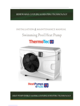
Swimming Pool
Heat Pump
Inverboost C
VERZE 17. 01. 2020 / 17. 01. 2020
EN
INSTALLATION
AND USER GUIDE

2 / Swimming Pool Heat Pump Inverboost C
Regulation (EU) n° 517/2014 of 16/04/14 on fluorinated greenhouse gases and repealing Regulation
(EC) n° 842/2006
Leak checks
1. Operators of equipment that contains fluorinated greenhouses gases in quantities of 5 tons of CO2,
equivalent or more and not contained in foams shall ensure that the equipment is checked for leaks.
2. For equipment that contains fluorinated greenhouse gases in quantities of 5 tons of CO2 equivalent
or more, but of less than 50 tons of CO2 equivalent: at least every 12 months.
Picture of the equivalence CO2
1. . Load in kg and Tons amounting CO2.
Concerning the Gas R32, 7.40kg amounting at 5 tons of CO2, commitment to check each year.
Training and certification
1. The operator of the relevant application shall ensure that the relevant personnel have obtained
the necessary certification, which implies appropriate knowledge of the applicable regulations
and standards as well as the necessary competence in emission prevention and recovery of
fluorinated greenhouse gases and handling safety the relevant type and size of equipment.
Record keeping
1. Operators of equipment which is required to be checked for leaks, shall establish and maintain
records for each piece of such equipment specifying the following information:
a) The quantity and type of fluorinated greenhouse gases installed;
b) The quantities of fluorinated greenhouse gases added during installation, maintenance or
servicing or due to leakage;
c) Whether the quantities of installed fluorinated greenhouse gases have been recycled or
reclaimed, including the name and address of the recycling or reclamation facility and, where
applicable, the certificate number;
d) The quantity of fluorinated greenhouse gases recovered
e) The identity of the undertaking which installed, serviced, maintained and where applicable
repaired or decommissioned the equipment, including, where applicable, the number of its
certificate;
f) The dates and results of the checks carried out;
g) If the equipment was decommissioned, the measures taken to recover and dispose of the
fluorinated greenhouse gases.
2. The operator shall keep the records for at least five years, undertakings carrying out the activities
for operators shall keep copies of the records for at least five years.
Do no release R32 coolant liquid into the atmosphere. This is a fluoride greenhouse effect
gas covered by the Kyoto agreement with a global warming potential (GWP) = 675 - (see
the European Community regulations on fluoride greenhouse effect gases Regulation (EU)
No 517/2014).
Load and Tons amounting CO2Frequency of test
From 7 at 75 kg load = from 5 at 50 Tons Each year

Swimming Pool Heat Pump Inverboost C / 3
1. Dimension .................................................................................................................. 4
2. Transport information .............................................................................................. 6
3. Specifications .............................................................................................................7
4. Accessories and options ......................................................................................... 8
5. Location and connection ...................................................................................... 10
6. Electrical Wiring .......................................................................................................13
7. Initial operation ........................................................................................................15
8. Troubleshooting ......................................................................................................23
9. Exploded view .........................................................................................................30
10. Maintenance ............................................................................................................34
11. Winterization ............................................................................................................34
Thank you for using BRILIX swimming pool heat pump for your pool heating, it will heat your pool
water and keep the constant temperature when the air ambient temperature is at 10 to 43°C.
Index
Important notice:
1 Please always keep the heat pump in a well ventilated place and away from anything
which could cause fire.
2 Do not braze or weld the pipe if there is refrigerant inside machine. Please do not
charge the gas when in a confined space.
3 Please always empty the water in heat pump during winter time or when the ambient
temperature drops below 0 °C, or else the Titanium exchanger will be damaged
because of being frozen, in such case, your warranty will be lost.
4 Please always cut the power supply if you want to open the cabinet to reach inside the
heat pump.
5 Please keep the display controller in a dry area to protect the display controller from
being damaged by humidity.
6 Action of filling gas must be conducted by professional with R32 operating license.
ATTENTION: This manual includes all the necessary information for the use and
the installation of your heat pump.
• The installer must read the manual and follow the instructions of implementation and
maintenance.
• The installer is responsible for the installation of the product and should follow all the
instructions of the manufacturer and the regulations in application. Incorrect installation
will invalidate the guarantee.
• The manufacturer declines any responsibility for the damage caused by any third party,
object ingression and of the errors due to the installation that do not follow the manual
guidelines. Any use that is not as intended by the manufacturer will invalidate the guarantee.

4 / Swimming Pool Heat Pump Inverboost C
1.1. Included with your Heat Pump
• Water connection assembly 50 mm (pcs: 2)
• User and service manual
• Drain connection (qty: 2)
• Drain hose (qty: 2)
• 10 meters’ signal wire
• Waterproof box
• Anti-vibration base (pcs: 4)
1.2. Dimension (unit: mm)
XHPFDPLUS100E
Dimension
1.

Swimming Pool Heat Pump Inverboost C / 5
XHPFDPLUS160E

6 / Swimming Pool Heat Pump Inverboost C
2.1. Delivery of the unit
For the transportation, the heat pumps are fixed on the pallet and covered with a cardboard box. To
protect from any damage, the heat pump must be transferred in its package.
It is the responsibility of the addressee to notify of any damage incurred during delivery within 48hours.
No responsibility can be taken once the unit has been signed for.
2.2. Stock advice
• The warehouse should be bright, spacious, open, well ventilated, have Fan equipment and no fire
source.
• Heat pumps must be stored and transferred in vertical position in its original packaging. If it is not the
case, it cannot be operated until a minimum period of 24H has passed before the unit can have the
electrical power turned on.
FORBIDDEN
2.3. Transfer to the final position
1) During the unpacking of the product and the transfer from the pallet to the final place of
installation, it is necessary to maintain the heat pump in a vertical position.
2) Smoking and the use of flames are prohibited near R32 machine.
3) Water connection are not to be used as load bearing handles. The manufacturer would not take
the responsibility in case of damage to the water pipes.
Transport information
2.

Swimming Pool Heat Pump Inverboost C / 7
Specifications 3.
3.1. Technical data Inverboost heat pumps
CE Standard, R32, Steel Cabinet
Model XHPFDPLUS100E XHPFDPLUS160E
* Performance at Air 28°C, Water 28°C, Humidity 80%
Heating capacity kW 9-2.3 16-3.8
Power consumption kW 1.55-0.18 2.67-0.29
C.O.P. 13-5.8 13-6
* Performance at Air 15°C, Water 26°C, Humidity 70%
Heating capacity kW 6.6-1.9 11.2-3
Power consumption kW 1.43-0.27 2.43-0.42
C.O.P. 7.1-4.6 7.2-4.6
* General data
Compressor type MITSUBISHI MITSUBISHI
Voltage V 220~240V / 50Hz or 60Hz /1PH
Rated current A 6,9 11,8
Minimum fuse A 10 18
Advised pool volume (with pool cover) m³ 12-33 25-85
Advised water flux m3/h 2,8 4,6
Water pressure drop Kpa 12 15
Heat exchanger Twist-titanium tube in PVC
Water connection mm 50
Ventilation type Horizontal
Fan speed ot/min. 500-850 550-850
Noise level(1m) dB(A) 40-52 41-54
Refrigerant (R32) g 650 1100
CO2 equivalent Tonne 0,44 0,74
* Dimension/ Weight
Net weight kg 56 78
Gross weight kg 68 83
Net dimension mm 937*360*554 1057*410*696
Packing dimension mm 995*405*580 1115*475*720

8 / Swimming Pool Heat Pump Inverboost C
4.1. Accessories list
4.2. The Kit By-Pass
The By-Pass Kit is the essential accessory for the installation of your heat pump, it is also a tool for
the optimization of the heating of the water. The valves allows the optimum flow of water using
a manometer to make sure the optimized running of the compressor, see paragraph 5.6 controls of
the pressure.
Accessories and options
4.
Anti-vibration base,
4 pcs
Draining plug,
2 pcs
Waterproof box,
1 pc
10M Signal wire,
1 pc
Water connection assembly,
2 sets
Drain hose, 2 pcs

Swimming Pool Heat Pump Inverboost C / 9
Anti-vibration bases
1. Take out 4 Anti-vibration bases
2. Install them on the bottom of machine.
Water Inlet & outlet connection
1. Install the two joints like the picture
shows
2. Screw them onto the water Inlet &
outlet connection
Mains Cable wiring
1. Open the top cover of the heat pump.
2. Connect the cables in the correct
terminal according to electric diagram.
Filtration pump wiring
(Dry contact)
1. Open the top cover of the heat pump.
2. Connect the cables in the correct terminal
according to electric diagram.
Draining plug
1. Install the draining plug under the
bottom panel
2. Attach the drain hose to the drain
connection through which the
condensate accumulated in the heat
pump base will drain.
Note: Lift the heat pump to install the.
Never overturn the heat pump, it could
damage the compressor.
4.3. Accessories Installation

10 / Swimming Pool Heat Pump Inverboost C
5.1. Heat pump location
The unit will work properly in any desired location as long as the following three items are present:
1. Fresh air
2. Electricity
3. Pool water flow
The unit may be installed in virtually any outdoor location as long as the specified minimum distances
to other objects are maintained (see drawing below). Please consult your installer for installation with
an indoor pool. Installation in a windy location does not present any problem at all.
The maximum height at which the heat pump can be installed is 1 metre.
To guarantee the required efficiency, the maximum distance of the pump from the pool circulation
pump is 7.5 metres.
Location and connection
5.
ATTENTION:
Please observe the following rules when installing the heat pump:
1. Any addition of chemicals must take place in the piping located downstream from the
heat pump.
2. Always keep the heat pump upright. If the unit has been held at an angle, wait at least
24 hours before applying mains power to the heat pump.
ATTENTION:
Never install the unit in a closed room with a limited air volume in which the air expelled
from the unit will be reused, or close to shrubbery that could block the air inlet. Such
locations impair the continuous supply of fresh air, resulting in reduced efficiency and
possibly preventing sufficient heat output.
See the drawing below for minimum dimensions
Air inlet
Air outlet
Air in
Air out

Swimming Pool Heat Pump Inverboost C / 11
Note: If automatic dosing equipment for chlorine and acidity (pH) is used, it is essential
to protect the heat pump against excessively high chemical concentrations which may
corrode the heat exchanger. For this reason, equipment of this sort must always be fitted
in the piping on the downstream side of the heat pump, and it is recommended to install
acheck-valve to prevent reverse flow in the absence of water circulation.
Damage to the heat pump caused by failure to observe this instruction is not covered by
the warranty.
NOTE
5.2. Check-valve installation
Item Product description
1 Filter
2 Check-valve
3 Chlorinator
4 Water Pump
5 P-trap
6 Check-valve
7 In-linw Chlorinator or Brominator
1
2
3
4
5
6
7

12 / Swimming Pool Heat Pump Inverboost C
ATTENTION:
In order to heat the water in the pool (or hot tub), the filtration pump must be running to cause the
water to circulate through the heat pump. The heat pump will not start up if the water is not circulating.
The factory supplies only the heat pump. All other components, including a bypass if necessary,
must be provided by the user or the installer.
NOTE
Item Product description
1 Heat pump
2 Water processor
3 Side connection valve
4 Power cable inlet
5 Outlet
6 Inlet
7 Condensed water draining pipe
8 Draining nozzle
9 Discharge water pool
10 Pool water inlet
11 Water pump
12 Filter
Note: This arrangement is only an illustrative example
5.3. Typical arrangement
4
1
5
2 3
11 1210987
6

Swimming Pool Heat Pump Inverboost C / 13
Electrical Wiring 6.
Item Description
1 Reactor
2 Magnet ring WHT
3 Magnet ring BLK
4FAN
5 FAN 2
6 Compressor
7 Electronic Expansion Valve
8 4-Way valve coil
9 Base Electric heater
10 Crankshaft electric heating
Item Description
11 Ambient temperature
12 Coil temperature
13 Exhaust temperature
14 Water out temperature
15 Water in temperature
16 Wire controller
17 Water flow switch
18 High pressure switch
19 Low pressure switch
20 Switch (pump)
11 2 4
6
5
2
3
20
*The dotted line part are only used in some models
191817
3
16
15141211 13
7
8
109
220V-240V~50Hz
RED
RED
BLU
BRN
YLW/GRN
TS1 TS2 TS5TS4TS3
PE
AC-N
AC-L
COM1
COM2
PE
WHT
BLK
RED
W
V
UJTAG
RED
RED I1
I2
OUT9
NO
COM
OUT6 OUT5 OUT4
N6 N5 N4
N2
N3
OUT3
N9
N1
OUT2 OUT1
COM
OUT10
1
2
NO
NO
3
TH1 TH2 TH5TH4TH3 TH8TH7TH6
NOTE:
(1) Above electrical wiring diagram only for your reference, please subject machine posted the wiring
diagram.
(2) The swimming pool heat pump must be connected ground wire well, although the unit heat
exchanger is electrically isolated from the rest of the unit. Grounding the unit is still required to
protect you against short circuits inside the unit. Bonding is also required.
Disconnect: A disconnect means (circuit breaker, fused or un-fused switch) should be located within
sight of and readily accessible from the unit. This is common practice on commercial and residential
heat pumps. It prevents remotely-energizing unattended equipment and permits turning off power at
the unit while the unit is being serviced.
Model: XHPFDPLUS100E/XHPFDPLUS160E

14 / Swimming Pool Heat Pump Inverboost C
6.1. Electrical protection
The power supply for the heat pump must come, preferably, from an exclusive circuit with regulatory
protection components (30mA dierential protection) and a magneto-thermal switch.
• The electrical installation must be carried out by a specialized professional (electrician) in accordan-
ce with the standards and regulations in force in the country of installation.
• The heat pump circuit must be connected to a safety earth circuit at the terminal block.
• The cables must be properly installed to prevent interference.
• The pump is intended for connection to a general power supply with earth connection.
• Section of the cable; This section is indicative and should be checked and adapted according to the
needs and conditions of use.
• The tolerance of acceptable voltage variation is +/- 10% during operation.
The connections must be dimensioned according to the power of the device and the state of installation.
6.2. Installation of the display deportee
Photo 02 Photo 03 Photo 04
6.3. Connection to pilot the water pump
Photo 01
Photo 01 Photo 02 Photo 03
• The end with plug connects with the control panel (photo1)
• The other end of the signal wire. (photo2)
• Open the top cover of the heat pump, connect the end of signal wire through the cable ring.
(photo3)
• Insert the wiring into the designated position (code:COM 1 or COM-L) on the PC board. (photo4)
• Open the button upwards as (Photo 1 )
• Fix the dry contact wiring through the two holes as (Photo 2 & Photo 4)
• Press down the button and tighten the wiring as (Photo 3 )
Photo 04

Swimming Pool Heat Pump Inverboost C / 15
Initial operation 7.
7.1. Initial operation
Note: In order to heat the water in the pool (or hot tub), the filter pump must be running to cause
the water to circulate through the heat pump. The heat pump will not start up if the water is not
circulating.
After all connections have been made and checked, carry out the following procedure:
1. Switch on the filtration pump. Check for leaks and verify that water is flowing from and to the
swimming pool.
2. Connect power to the heat pump and press the On/Off button on the electronic control panel.
The unit will start up after the time delay expires (see below).
3. After a few minutes, check whether the air blowing out of the unit is cooler.
4. When turn off the filtration pump, the unit should also turn off automatically, if not, then adjust the
flow switch.
5. Allow the heat pump and the filter pump to run 24 hours a day until the desired water temperature is
reached. The heat pump will stop running at this point +1°C. After this, it will restart automatically
(as long as the filtration pump is running) whenever the swimming pool water temperature drops
1 degree below the set temperature (for example, if you set the temperature 28°C, the heat pump
will stop when the temperature at 29°C. While it will restart when the temperature of the water
down to 27°C)
Depending on the initial temperature of the water in the swimming pool and the air temperature, it
may take several days to heat the water to the desired temperature. A good swimming pool cover can
dramatically reduce the required length of time.
1 m above or below the heat pump’s automatic adjustment knob, your dealer may need to adjust its
initial startup.
Time delay - The heat pump has a built-in 3-minute start-up delay to protect the circuitry and avoid
excessive contact wear. The unit will restart automatically after this time delay expires. Even a brief
power interruption will trigger this time delay and prevent the unit from restarting immediately.
Additional power interruptions during this delay period do not affect the 3-minute duration of the
delay.
Water Flow Switch:
It is equipped with a flow switch for protecting the HP unit running with adequate water
flow rate. It will turn on when the filtration pump runs and shut it off when the pump shuts
off. If the pool water level higher than 1 m above or below the heat pump’s automatic
adjustment knob, your dealer may need to adjust its initial startup.
NOTE

16 / Swimming Pool Heat Pump Inverboost C
7.2. Condensation
The air drawn into the heat pump is strongly cooled by the operation of the heat pump for heating the
pool water, which may cause condensation on the fins of the evaporator.
7.3. Pressure gauge display (R32)
Examine the pressure gauge which indicates the refrigerant gas pressure of the unit, the below
table shows the normal value of the gas pressure (R32) when the machine is in power off or running
conditions.
The amount of condensation may be as much as several litres per hour at high relative
humidity. The condensate will drain from the bottom of the heat pump. This is sometimes
mistakenly regarded as a heat exchanger leak.
NOTE
Unit Condition Power Off
Ambient (°C) -5~5 5~15 15~25 25~35
Water temp (°C) / / / /
Pressure gauge (Mpa) 0,59~0,85 0,85~1,18 1,18~1,59 1,59~2,1
Unit Condition Running
Ambient (°C) / / / / /
Water temp (°C) 10~15 15~20 20~25 25~30 30~35
Pressure gauge (Mpa) 1,1~1,6 1,3~1,8 1,5~2,1 1,7~2,4 1,9~2,7

Swimming Pool Heat Pump Inverboost C / 17
7.4. Display Controller Operation
NOTE: When the heat pump connects to the power, the LED display shows a code for 3 seconds
which indicates the heat pump model.
7.4.1. button
Press to start the heat pump unit, the LED display shows the desired water temperature for
5seconds, then shows the inlet water temperature and the operation mode.
Press to stop the heat pump unit and show “OFF”.
Notice: During the parameter checking and setting, press the to quick-exit and save the current
setting .
Press again to turn on/off the machine.
7.4.2. button
Automatic mode:
There are 3 modes for the unit, Heating only, Auto mode (heating and cooling switch), Cooling only.
You can switch Heating only and Auto mode by pressing for 5 seconds, no matter the unit is on
or off. (default: Smart mode).
Press for 5 seconds again to exit automatic mode and switch to heating mode (default: Smart
mode)
Note: Under Automatic mode, it is useless to set parameter P1 .

18 / Swimming Pool Heat Pump Inverboost C
Operation logic of Auto Mode:
Auto Mode
Heating mode
Logic of auto mode
Heating Standby Heating Heating
CoolingStandby
Standby
Tset=28°C

Swimming Pool Heat Pump Inverboost C / 19
7.4.3. Button and
Lock / Unlock the display:
Hold and for 5 seconds to lock/unlock the display.
Water temperature setting:
Press or to set the water temperature directly.
Parameter checking:
Press first, then press to check the “ User parameter from d0 to d11
Remark: d4: Frequency limitation code, 0: No frequency limit,
1: Coil pipe temperature limit, 2: Overheating or overcooling frequency limit
4 Drive Current frequency limit 8: Drive voltage frequency limit
16: Drive high temperature frequency limit.
Press first, then press to check/adjust the User parameter from P0 to P7
If needed, press second, then press or to adjust the current parameter.
(for example: Press first, then press to enter parameter P7 checking, and press second,
then press or to adjust the parameter P7 Inlet water temp. Correction from -9 to 9.)
NOTE: Under defrosting mode, P0=1. After defrosting finished, it will be automatic enter Normal
mode, P0=0.
Code Condition Scope Remark
d0 IPM mould temperature 0-120°C Real testing value
d1 Inlet water temp. -9°C~99°C Real testing value
d2 Outlet water temp. -9°C~99°C Real testing value
d3 Ambient temp. -30°C~70°C Real testing value
d4 Frequency limitation code 0,1,2,4,8,16 Real testing value
d5 Piping temp. -30°C~70°C Real testing value
d6 Gas discharge temperature 0°C~C5°C (125°C) Real testing value
d7 Step of EEV 0~99 N*5
d8 Compressor running frequency 0~99Hz Real testing value
d9 Compressor current 0~30A Real testing value
d10 Current fan speed 0-1200 (rpm) Real testing value
d11 Error code for last time All error code
Code Name Scope Defaul Remark
P0 Mandatory defrosting 0-1 0 0: Default normal operation
1: mandatory defrosting.
P1 Working mode 0-1 1 1:Heating mode,
0:cooling mode,
P2 Timer on/off 0-1 0
1 Timer on/off is under function.
0 Timer on/off is out of function
(The setting of P5 and P6 won’t work)
P3 Water pump 0-1 0 1: Always running;
0: Depends on the running of compressor
P4 Current time HH:MM 00:00 0-23:0-59
P5 Timer on HH:MM 00:00 0-23:0-59
P6 Timer off HH:MM 00:00 0-23:0-59
P7 Water temp. calibration -9~9 0 Výchozí nastavení: 0

20 / Swimming Pool Heat Pump Inverboost C
7.4.4. System reset function
Press and in 10s, the system will reset and display “0000” on the controller.
7.4.5.
Symbol of heating, the light will be on when it is in operation.
When defrosting, the light will flash.
7.4.6.
Symbol of cooling, the light will be on when it is in operation.
Note: When parameter P1 is on checking/adjusting, and will be flashing at the
same time.
7.4.7.
Symbol of automatic stop, the light will be on when it is in operation.
7.4.8.
Symbol of automatic start, the light will be on when it is in operation.
7.4.9.
Press this button, the light will be flash, the heat pump will operate in ‘Full output’ only.
7.4.10.
While you choose the Smart, the heat pump will just operate in ‘Medium output’ and ‘Full output’
When in ‘Medium output’, the light of Smart will flash.
When in ‘Full output’, the lamp of Smart is lit, the lamp of Powerful will be flash.
7.4.11.
While you choose the Silent, the heat pump will just operate in ‘Medium output’ and ‘Small output’
When in ‘Small output’, the lamp of Silent will flash.
When in ‘Medium output’, the lamp of Silent is lit, the lamp of Smart will flash.
/