
Motherboard
H81M-P

ii
E9807
First Edition
October 2014
Copyright © 2014 ASUSTeK COMPUTER INC. All Rights Reserved.
No part of this manual, including the products and software described in it, may be reproduced,
transmitted, transcribed, stored in a retrieval system, or translated into any language in any form or by any
means, except documentation kept by the purchaser for backup purposes, without the express written
permission of ASUSTeK COMPUTER INC. (“ASUS”).
Product warranty or service will not be extended if: (1) the product is repaired, modied or altered, unless
such repair, modication of alteration is authorized in writing by ASUS; or (2) the serial number of the
product is defaced or missing.
ASUS PROVIDES THIS MANUAL “AS IS” WITHOUT WARRANTY OF ANY KIND, EITHER EXPRESS
OR IMPLIED, INCLUDING BUT NOT LIMITED TO THE IMPLIED WARRANTIES OR CONDITIONS OF
MERCHANTABILITY OR FITNESS FOR A PARTICULAR PURPOSE. IN NO EVENT SHALL ASUS, ITS
DIRECTORS, OFFICERS, EMPLOYEES OR AGENTS BE LIABLE FOR ANY INDIRECT, SPECIAL,
INCIDENTAL, OR CONSEQUENTIAL DAMAGES (INCLUDING DAMAGES FOR LOSS OF PROFITS,
LOSS OF BUSINESS, LOSS OF USE OR DATA, INTERRUPTION OF BUSINESS AND THE LIKE),
EVEN IF ASUS HAS BEEN ADVISED OF THE POSSIBILITY OF SUCH DAMAGES ARISING FROM ANY
DEFECT OR ERROR IN THIS MANUAL OR PRODUCT.
SPECIFICATIONS AND INFORMATION CONTAINED IN THIS MANUAL ARE FURNISHED FOR
INFORMATIONAL USE ONLY, AND ARE SUBJECT TO CHANGE AT ANY TIME WITHOUT NOTICE,
AND SHOULD NOT BE CONSTRUED AS A COMMITMENT BY ASUS. ASUS ASSUMES NO
RESPONSIBILITY OR LIABILITY FOR ANY ERRORS OR INACCURACIES THAT MAY APPEAR IN THIS
MANUAL, INCLUDING THE PRODUCTS AND SOFTWARE DESCRIBED IN IT.
Products and corporate names appearing in this manual may or may not be registered trademarks or
copyrights of their respective companies, and are used only for identication or explanation and to the
owners’ benet, without intent to infringe.
Offer to Provide Source Code of Certain Software
This product contains copyrighted software that is licensed under the General Public License (“GPL”),
under the Lesser General Public License Version (“LGPL”) and/or other Free Open Source Software
Licenses. Such software in this product is distributed without any warranty to the extent permitted by the
applicable law. Copies of these licenses are included in this product.
Where the applicable license entitles you to the source code of such software and/or other additional data,
you may obtain it for a period of three years after our last shipment of the product, either
(1) for free by downloading it from http://support.asus.com/download
or
(2) for the cost of reproduction and shipment, which is dependent on the preferred carrier and the location
where you want to have it shipped to, by sending a request to:
ASUSTeK Computer Inc.
Legal Compliance Dept.
15 Li Te Rd.,
Beitou, Taipei 112
Taiwan
In your request please provide the name, model number and version, as stated in the About Box of the
product for which you wish to obtain the corresponding source code and your contact details so that we
can coordinate the terms and cost of shipment with you.
The source code will be distributed WITHOUT ANY WARRANTY and licensed under the same license as
the corresponding binary/object code.
This offer is valid to anyone in receipt of this information.
ASUSTeK is eager to duly provide complete source code as required under various Free Open Source
Software licenses. If however you encounter any problems in obtaining the full corresponding source
code we would be much obliged if you give us a notication to the email address [email protected], stating
the product and describing the problem (please DO NOT send large attachments such as source code
archives, etc. to this email address).

iii
Contents
Safety information ...................................................................................................... iv
About this guide ......................................................................................................... iv
Package contents ....................................................................................................... vi
H81M-P specications summary .............................................................................. vi
Chapter 1: Product introduction
1.1 Before you proceed ...................................................................................... 1-1
1.2 Motherboard overview ................................................................................. 1-1
1.3 Central Processing Unit (CPU) .................................................................... 1-4
1.4 System memory ............................................................................................ 1-7
1.6 Headers ....................................................................................................... 1-11
1.7 Connectors .................................................................................................. 1-12
1.9 Software support ........................................................................................ 1-20
Chapter 2: BIOS information
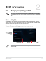
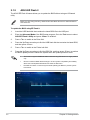
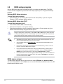
2.1 Managing and updating your BIOS ............................................................. 2-1
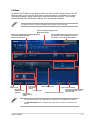
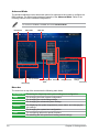
2.2 BIOS setup program ..................................................................................... 2-6
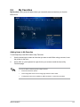
2.3 My Favorites.................................................................................................. 2-9
2.4 Main menu ................................................................................................... 2-10
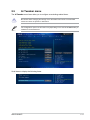
2.5 Ai Tweaker menu ........................................................................................ 2-11
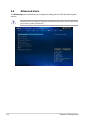
2.6 Advanced menu .......................................................................................... 2-12
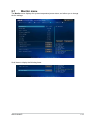
2.7 Monitor menu .............................................................................................. 2-13
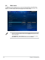
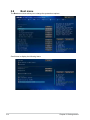
2.8 Boot menu ................................................................................................... 2-14
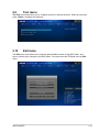
2.9 Tool menu ................................................................................................... 2-15
2.10 Exit menu .................................................................................................... 2-15
Appendices
Notices ..................................................................................................................... A-1
ASUS contact information ...................................................................................... A-3

iv
Safety information
Electrical safety
• To prevent electrical shock hazard, disconnect the power cable from the electrical outlet
before relocating the system.
• When adding or removing devices to or from the system, ensure that the power cables
for the devices are unplugged before the signal cables are connected. If possible,
disconnect all power cables from the existing system before you add a device.
• Before connecting or removing signal cables from the motherboard, ensure that all
power cables are unplugged.
• Seek professional assistance before using an adapter or extension cord. These devices
could interrupt the grounding circuit.
• Ensure that your power supply is set to the correct voltage in your area. If you are not
sure about the voltage of the electrical outlet you are using, contact your local power
company.
• If the power supply is broken, do not try to x it by yourself. Contact a qualied service
technician or your retailer.
Operation safety
• Before installing the motherboard and adding devices on it, carefully read all the manuals
that came with the package.
• Before using the product, ensure all cables are correctly connected and the power
cables are not damaged. If you detect any damage, contact your dealer immediately.
• To avoid short circuits, keep paper clips, screws, and staples away from connectors,
slots, sockets and circuitry.
• Avoid dust, humidity, and temperature extremes. Do not place the product in any area
where it may become wet.
• Place the product on a stable surface.
• If you encounter technical problems with the product, contact a qualied service
technician or your retailer.
About this guide
This user guide contains the information you need when installing and conguring the
motherboard.
How this guide is organized
This guide contains the following parts:
• Chapter 1: Product introduction
This chapter describes the features of the motherboard and the new technology it
supports.
• Chapter 2: BIOS information
This chapter tells how to change system settings through the BIOS Setup menus.
Detailed descriptions of the BIOS parameters are also provided.

v
Where to nd more information
Refer to the following sources for additional information and for product and software
updates.
1. ASUS websites
The ASUS website provides updated information on ASUS hardware and software
products. Refer to the ASUS contact information.
2. Optional documentation
Your product package may include optional documentation, such as warranty yers,
that may have been added by your dealer. These documents are not part of the
standard package.
Conventions used in this guide
To ensure that you perform certain tasks properly, take note of the following symbols used
throughout this manual.
DANGER/WARNING: Information to prevent injury to yourself when trying to
complete a task.
CAUTION: Information to prevent damage to the components when trying to
complete a task
IMPORTANT: Instructions that you MUST follow to complete a task. .
NOTE: Tips and additional information to help you complete a task.
Typography
Bold text Indicates a menu or an item to select.
Italics
Used to emphasize a word or a phrase.
<Key> Keys enclosed in the less-than and greater-than sign
means that you must press the enclosed key.
Example: <Enter> means that you must press the Enter or
Return key.
<Key1> + <Key2> + <Key3> If you must press two or more keys simultaneously, the key
names are linked with a plus sign (+).

vi
(continued on the next page)
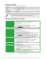
H81M-P specications summary
CPU LGA1150 socket for the 4th Generation and New 4th Generation Intel®
CoreTM i7/ i5 / i3, Pentium® and Celeron® Processors
Supports 22nm CPU
Supports Intel® Turbo Boost Technology 2.0*
* Intel® Turbo Boost Technology 2.0 support depends on the CPU types.
** Refer to www.asus.com for Intel® CPU support list.
Chipset Intel® H81 Express Chipset
Memory 2 x DIMMs, max. 16GB DDR3 1600/1333/1066MHz, non-ECC, unbuffered
memory modules
Dual-channel memory architecture
Supports Intel® Extreme Memory Prole (XMP)
* Hyper DIMM support is subject to the physical characteristics of individual
CPUs. Please refer to Memory QVL for details.
** Refer to www.asus.com for the latest Memory QVL (Qualied Vendors List).
*** Due to Intel® chipset limitations, DDR3 1600MHz and higher memory modules
on XMP mode will run at the maximum transfer rate of DDR3 1600MHz.
Graphics Integrated Graphics Processor - Intel® HD Graphics support
Multi-VGA output support: DVI-D, D-Sub port
- Supports DVI-D with max. resolution up to 1920 x1200@60Hz
- Supports D-Sub with max. resolution 1920x1200@60Hz
- Maximum shared memory of 1024MB
Expansion slots 1 x PCI Express x16 slot
1 x PCI Express x1 slot
Storage Intel® H81 Express Chipset:
- 2 x Serial ATA 6.0 Gb/s connectors (yellow)
- 2 x Serial ATA 3.0 Gb/s connectors (dark brown)
- Supports Intel® Rapid Start Technology* and Intel® Smart Connect
Technology**
* Due to the limitation of the Intel® H81 chipset, Intel® Rapid Start Technology can
be congured only from the BIOS Setup program.
** These functions will work depending on the CPU installed.
Package contents
Check your motherboard package for the following items.
Motherboard ASUS H81M-P motherboard
Cables 2 x Serial ATA 6.0 Gb/s cables
Accessories 1 x I/O Shield
Application DVD Support DVD
Documentation User Guide
If any of the above items is damaged or missing, contact your retailer.

vii
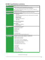
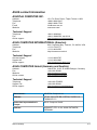
H81M-P specications summary
LAN Realtek® RTL8111GR Gigabit LAN Controller
Audio Realtek® ALC887 8-Channel High Denition Audio CODEC
- Supports Jack-Detection and Front Panel Jack-Retasking
* Use a chassis with HD audio module in the front panel to support an
8-channel audio output
USB 4 x USB 3.0 ports at rear panel (2 ports at mid-board, 2 ports at the rear panel)
6 x USB 2.0 ports (4 ports at mid-board, 2 ports at the rear panel)
ASUS unique
features
ASUS Exclusive Features:
- ASUS EPU
- ASUS UEFI BIOS EZ Mode featuring a friendly graphical user interface
- ASUS GPU Boost
- ASUS Ai Charger
- ASUS AI Suite 3
- ASUS Anti-surge Protection
- ASUS ESD
ASUS Quiet Thermal Solution
- ASUS Fan Xpert
ASUS EZ DIY:
- ASUS CrashFree BIOS 3
- ASUS EZ Flash 2
Back Panel I/O
ports
1 x PS/2 keyboard port (purple)
1 x PS/2 mouse port (green)
2 x USB 3.0 ports
2 x USB 2.0 ports
1 x DVI port
1 x D-Sub port
1 x LAN (RJ-45) port
3 x Audio jacks support 8-channel audio output
Internal
I/O connectors/
buttons/switches
2 x USB 2.0 connectors support additional 4 USB 2.0 ports
1 x USB 3.0 connectors support additional 2 USB 3.0 ports
2 x SATA 6.0Gb/s connectors
2 x SATA 3.0Gb/s connectors
1 x 4-pin CPU fan connector (PWM mode)
1 x 4-pin Chassis fan connector (PWM mode)
1 x Front panel audio connector
1 x 24-pin EATX power connector
1 x 4-pin EATX 12V power connector
1 x COM header
1 x LPT header
1 x TPM header
1 x CLRTC header
1 x Chassis Intrusion header
1 x Speaker connector
1 x System panel connector
(continued on the next page)

viii
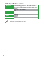
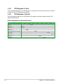
H81M-P specications summary
Specications are subject to change without notice.
BIOS features 64 Mb Flash ROM, UEFI AMI BIOS, PnP, DMI2.0, WfM2.0, SM BIOS 2.7,
ACPI 2.0a, Multi-language BIOS, ASUS EZ Flash 2, ASUS CrashFree
BIOS 3, My Favorites, Quick Note, Last Modied log, F12 PrintScreen, F3
Shortcut functions and ASUS DRAM SPD (Serial Presence Detect) memory
information
Manageability WfM 2.0, DMI 2.0, WOL by PME, PXE
Support DVD Drivers
ASUS utilities
EZ Update
Anti-virus software (OEM version)
Operating System
Support
Windows® 8.1
Windows® 8
Windows® 7
Form factor uATX form factor: 7.5 in x 7.0 in (19 cm x 17.7 cm)

ASUS H81M-P 1-1
Product introduction
1
1.1 Before you proceed
Take note of the following precautions before you install motherboard components or change
any motherboard settings.
• Unplugthepowercordfromthewallsocketbeforetouchinganycomponent.
• Beforehandlingcomponents,useagroundedwriststraportouchasafelygrounded
objectorametalobject,suchasthepowersupplycase,toavoiddamagingthemdue
to static electricity.
• HoldcomponentsbytheedgestoavoidtouchingtheICsonthem.
• Wheneveryouuninstallanycomponent,placeitonagroundedantistaticpadorinthe
bag that came with the component.
• Beforeyouinstallorremoveanycomponent,ensurethattheATXpowersupplyis
switched off or the power cord is detached from the power supply. Failure to do so
maycauseseveredamagetothemotherboard,peripherals,orcomponents.
1.2 Motherboard overview
Beforeyouinstallthemotherboard,studythecongurationofyourchassistoensurethatthe
motherboardtsintoit.
Ensurethatyouunplugthepowercordbeforeinstallingorremovingthemotherboard.
Failure to do so can cause you physical injury and damage motherboard components.
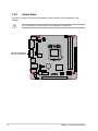
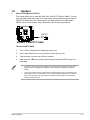
1.2.1 Placement direction
Wheninstallingthemotherboard,ensurethatyouplaceitintothechassisinthecorrect
orientation. The edge with external ports goes to the rear part of the chassis as indicated in
the image below.

1-2 Chapter 1: Product introduction
H81M-P
Place this side towards
the rear of the chassis
1.2.2 Screw holes
Place four screws into the holes indicated by circles to secure the motherboard to the
chassis.
Donotovertightenthescrews!Doingsocandamagethemotherboard.

ASUS H81M-P 1-3
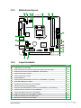
1.2.3 Motherboard layout
H81M-P
PCIEX16
PCIEX1_1
Realtek®
8111GR
ASM
1042
AAFP
COM
EATXPWR
BATTERY
Super
I/O
ALC
887
KBMS
CLRTC
SPEAKER
17.7cm(7.0in)
DDR3 DIMM_A1 (64bit, 240-pin module)
DDR3 DIMM_B1 (64bit, 240-pin module)
SATA6G_2 SATA6G_1
SATA3G_1
SATA3G_2
AUDIO
VGA DVI
CHA_FAN
CPU_FAN
LAN_USB34
USB3_12
19cm(7.5in)
LGA1150
Intel®
H81
ATX12V
F_PANEL
TPM
USB910
USB56
CHASSIS
64Mb
BIOS
LPT
USB3_E12
1 2 3 24 65
14
13 12
3
7
9
10
11
8
16
15
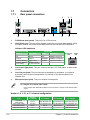
1.2.4 Layout contents
Connectors/Jumpers/Slots/LED Page
1. TPM header (14-1 pin TPM) 1-19
2. CPUandchassisfanconnectors(4-pinCPU_FAN,4-pinCHA_FAN) 1-14
3. ATXpowerconnectors(24-pinEATXPWR,4-pinATX12V) 1-16
4. LPT connector (26-1 pin LPT) 1-18
5. Intel®LGA1150CPUsocket 1-4
6. DDR3DIMMslots 1-7
7. Intel®H81SerialATA6.0Gb/sconnector(7-pinSATA6G_1~2[yellow]) 1-17
8. ClearRTCRAM(2-pinCLRTC) 1-11
9. Systempanelconnector(10-1pinF_PANEL) 1-19
10. Speakerconnector(4-pinSPEAKER) 1-16
11. Intel®H81SerialATA3.0Gb/sconnector(7-pinSATA3G_1~2[darkbrown]) 1-17
12. Chassisintrusionconnector(4-1pinCHASSIS) 1-18
13. Frontpanelaudioconnector(10-1pinAAFP) 1-14
14. USB2.0connectors(10-1pinUSB910,USB56) 1-15
15. USB3.0connectors(20-1pinUSB3_E12) 1-15
16. Serialportconnectors(10-1pinCOM) 1-13

1-4 Chapter 1: Product introduction
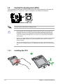
1.3 Central Processing Unit (CPU)
ThismotherboardcomeswithasurfacemountLGA1150socketdesignedfortheIntel® 4th
generationCore™i7/Core™i5/Core™i3,Pentium® andCeleron® processors.
H81M-P
H81M-P CPU socket LGA1150
UnplugallpowercablesbeforeinstallingtheCPU.
• Uponpurchaseofthemotherboard,ensurethatthePnPcapisonthesocketand
thesocketcontactsarenotbent.ContactyourretailerimmediatelyifthePnPcap
ismissing,orifyouseeanydamagetothePnPcap/socketcontacts/motherboard
components.ASUSwillshoulderthecostofrepaironlyifthedamageisshipment/
transit-related.
• Keepthecapafterinstallingthemotherboard.ASUSwillprocessReturnMerchandise
Authorization(RMA)requestsonlyifthemotherboardcomeswiththecaponthe
LGA1150socket.
• Theproductwarrantydoesnotcoverdamagetothesocketcontactsresultingfrom
incorrectCPUinstallation/removal,ormisplacement/loss/incorrectremovalofthePnP
cap.
1.3.1 Installing the CPU
1
A
B

ASUS H81M-P 1-5
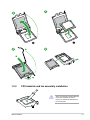
23
A
B
C
45
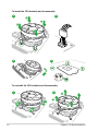
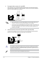
1.3.2 CPU heatsink and fan assembly installation
ApplytheThermalInterfaceMaterial
totheCPUheatsinkandCPU
before you install the heatsink and
fan if necessary.

1-6 Chapter 1: Product introduction
To install the CPU heatsink and fan assembly
2
B
A
A
B
1
3 4
A
B
B
A
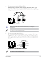
To uninstall the CPU heatsink and fan assembly
2
1

ASUS H81M-P 1-7
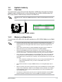
1.4 System memory
1.4.1 Overview
ThismotherboardcomeswithtwoDoubleDataRate3(DDR3)DualInlineMemoryModule
(DIMM)sockets.ADDR3moduleisnotcheddifferentlyfromaDDRorDDR2module.DO
NOTinstallaDDRorDDR2memorymoduletotheDDR3slot.
Channel Sockets
ChannelA DIMM_A1
ChannelB DIMM_B1
H81M-P
H81M-P 240-pin DDR3 DIMM sockets
DIMM_A1
DIMM_B1
1.4.2 Memorycongurations
Youmayinstall1GB,2GB,4GB,and8GBunbufferednon-ECCDDR3DIMMsintotheDIMM
sockets.
• YoumayinstallvaryingmemorysizesinChannelAandChannelB.Thesystem
mapsthetotalsizeofthelower-sizedchannelforthedual-channelconguration.Any
excessmemoryfromthehigher-sizedchannelisthenmappedforsingle-channel
operation.
• DuetoIntel®chipsetlimitations,DDR31600MHzandhighermemorymoduleson
XMPmodewillrunatthemaximumtransferrateofDDR31600MHz.
• AlwaysinstallDIMMswiththesameCASlatency.Foroptimalcompatibility,we
recommendthatyouinstallmemorymodulesofthesameversionordatecode(D/C)
fromthesamevendor.Checkwiththeretailertogetthecorrectmemorymodules.
• Duetothememoryaddresslimitationon32-bitWindows®OS,whenyouinstall4GB
ormorememoryonthemotherboard,theactualusablememoryfortheOScanbe
about3GBorless.Foreffectiveuseofmemory,werecommendthatyoudoanyofthe
following:
- Useamaximumof3GBsystemmemoryifyouareusinga32-bitWindows®OS.
- Installa64-bitWindows®OSifyouwanttoinstall4GBormoreonthe
motherboard.
• ThismotherboarddoesnotsupportDIMMsmadeupof512megabits(Mb)chipsor
less.
• Memorymoduleswithmemoryfrequencyhigherthan2133MHzanditscorresponding
timingortheloadedX.M.P.ProleisnottheJEDECmemorystandard.Thestability
andcompatibilityofthesememorymodulesdependontheCPU’scapabilitiesand
otherinstalleddevices.
• Themaximum16GBmemorycapacitycanbesupportedwith8GBoraboveDIMMs.
ASUSwillupdatethememoryQVLoncetheDIMMsareavailableinthemarket.
AccordingtoIntel®CPUspec,DIMMvoltagebelow1.65Visrecommendedtoprotectthe
CPU.

1-8 Chapter 1: Product introduction
• ThedefaultmemoryoperationfrequencyisdependentonitsSerialPresenceDetect
(SPD),whichisthestandardwayofaccessinginformationfromamemorymodule.
Underthedefaultstate,somememorymodulesforoverclockingmayoperateata
lowerfrequencythanthevendor-markedvalue.
• Forsystemstability,useamoreefcientmemorycoolingsystemtosupportafull
memoryload(2DIMMs)oroverclockingcondition.
• Refertowww.asus.comforthelatestMemoryQVL(QualiedVendorsList)
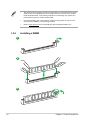
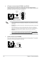
1.4.3 Installing a DIMM
1
2
3

ASUS H81M-P 1-9
To remove a DIMM
BA
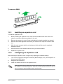
1.5.1 Installing an expansion card
To install an expansion card:
1. Beforeinstallingtheexpansioncard,readthedocumentationthatcamewithitand
make the necessary hardware settings for the card.
2. Removethesystemunitcover(ifyourmotherboardisalreadyinstalledinachassis).
3. Removethebracketoppositetheslotthatyouintendtouse.Keepthescrewforlater
use.
4. Alignthecardconnectorwiththeslotandpressrmlyuntilthecardiscompletely
seated on the slot.
5. Securethecardtothechassiswiththescrewyouremovedearlier.
6. Replacethesystemcover.
1.5.2 Conguringanexpansioncard
Afterinstallingtheexpansioncard,congureitbyadjustingthesoftwaresettings.
1. TurnonthesystemandchangethenecessaryBIOSsettings,ifany.SeeChapter2for
informationonBIOSsetup.
2. AssignanIRQtothecard.
3. Installthesoftwaredriversfortheexpansioncard.
WhenusingPCIcardsonsharedslots,ensurethatthedriverssupport“ShareIRQ”orthat
thecardsdonotneedIRQassignments.Otherwise,conictswillarisebetweenthetwoPCI
groups,makingthesystemunstableandthecardinoperable.

1-10 Chapter 1: Product introduction
IRQ assignments for this motherboard
A B C D E F G H
LAN - - shared - - - - -
PCIEx16 shared - - - - - -
PCIEx1_1 shared - - - - - - -
PCIEx1_2 - shared - - - - - -
IntelPCHSATAController - - - shared - - - -
HDAudio - - - - - - shared
USB2.0_1 - - - - - - - shared
USB2.0_2 - - - - shared - - -
USB3.0 - - - - - shared -
1.5.3 PCI Express x1 slot
ThismotherboardsupportsonePCIExpressx1networkcard,SCSIcard,andothercardthat
complywiththePCIExpressspecications.
1.5.4 PCI Express x16 slot
ThismotherboardsupportsonePCIExpressx16graphicscardthatcomplieswiththePCI
Expressspecications.

ASUS H81M-P 1-11
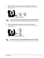
1.6 Headers
1. Clear RTC RAM (2-pin CLRTC)
ThisheaderallowsyoutocleartheRealTimeClock(RTC)RAMinCMOS.Youcan
cleartheCMOSmemoryofdate,time,andsystemsetupparametersbyerasingthe
CMOSRTCRAMdata.TheonboardbuttoncellbatterypowerstheRAMdatain
CMOS,whichincludesystemsetupinformationsuchassystempasswords.
H81M-P
H81M-P Clear RTC RAM
CLRTC
GND
+3V_BAT
PIN 1
To erase the RTC RAM:
1. TurnOFFthecomputerandunplugthepowercord.
2. Useametalobjectsuchasascrewdrivertoshortthetwopins.
3. PlugthepowercordandturnONthecomputer.
4. Holddownthe<Del>keyduringthebootprocessandenterBIOSsetuptore-
enter data.
• Ifthestepsabovedonothelp,removetheonboardbatteryandshortthetwopins
againtocleartheCMOSRTCRAMdata.AfterclearingtheCMOS,reinstallthe
battery.
• YoudonotneedtocleartheRTCwhenthesystemhangsduetooverclocking.For
systemfailureduetooverclocking,usetheCPUParameterRecall(C.P.R.)feature.
Shutdownandrebootthesystem,thentheBIOSautomaticallyresetsparameter
settingstodefaultvalues.

1-12 Chapter 1: Product introduction
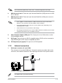
1.7 Connectors
1.7.1 Rear panel connectors
3 42
57 6
1
10 89
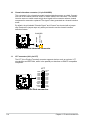
LAN port
Speed
LED
Activity Link
LED
LAN port LED indications
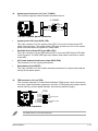
3. Line In port (light blue).Thisportconnectsthetape,CD,DVDplayer,orotheraudio
sources.
4. Line Out port (lime).Thisportconnectsaheadphoneoraspeaker.In4-channel,
6-channel,and8-channelcongurations,thefunctionofthisportbecomesFront
SpeakerOut.
5. Microphone port (pink). This port connects a microphone.
Tocongurean8-channelaudiooutput:
UseachassiswithHDaudiomoduleinthefrontpaneltosupportan8-channelaudio
output.
Activity/Link LED Speed LED
Status Description Status Description
Off Nolink OFF 10Mbpsconnection
Orange Linked ORANGE 100Mbpsconnection
Orange(Blinking) Dataactivity GREEN 1Gbps connection
Orange(Blinking
then steady)
Readytowake
upfromS5mode
Audio2.1,4.1,5.1or7.1-channelconguration
Port Headset
2.1-channel 4.1-channel 5.1-channel 7.1-channel
LightBlue
(Rearpanel) LineIn RearSpeakerOut RearSpeakerOut RearSpeakerOut
Lime(Rearpanel) LineOut FrontSpeakerOut FrontSpeakerOut FrontSpeakerOut
Pink(Rearpanel) MicIn MicIn Bass/Center Bass/Center
Lime (Front panel) — — — SideSpeakerOut
1. PS/2 Mouse port (green).ThisportisforaPS/2mouse.
2. LAN (RJ-45) port.ThisportallowsGigabitconnectiontoaLocalAreaNetwork(LAN)
throughanetworkhub.RefertothetablebelowfortheLANportLEDindications.
Page is loading ...
Page is loading ...
Page is loading ...
Page is loading ...
Page is loading ...
Page is loading ...
Page is loading ...
Page is loading ...
Page is loading ...
Page is loading ...
Page is loading ...
Page is loading ...
Page is loading ...
Page is loading ...
Page is loading ...
Page is loading ...
Page is loading ...
Page is loading ...
Page is loading ...
Page is loading ...
Page is loading ...
Page is loading ...
Page is loading ...
Page is loading ...
Page is loading ...
Page is loading ...
Page is loading ...
Page is loading ...
-
 1
1
-
 2
2
-
 3
3
-
 4
4
-
 5
5
-
 6
6
-
 7
7
-
 8
8
-
 9
9
-
 10
10
-
 11
11
-
 12
12
-
 13
13
-
 14
14
-
 15
15
-
 16
16
-
 17
17
-
 18
18
-
 19
19
-
 20
20
-
 21
21
-
 22
22
-
 23
23
-
 24
24
-
 25
25
-
 26
26
-
 27
27
-
 28
28
-
 29
29
-
 30
30
-
 31
31
-
 32
32
-
 33
33
-
 34
34
-
 35
35
-
 36
36
-
 37
37
-
 38
38
-
 39
39
-
 40
40
-
 41
41
-
 42
42
-
 43
43
-
 44
44
-
 45
45
-
 46
46
-
 47
47
-
 48
48


Asus H81M-CS User manual
- Category
- Motherboards
- Type
- User manual
Ask a question and I''ll find the answer in the document
Finding information in a document is now easier with AI
Related papers
Other documents
-
fabWeaver 32GB-MB032 USB Flash Drive Operating instructions
-
Gigabyte GA-H81M-S1 Owner's manual
-
ASROCK H81M-DGS R2.0 Specification
-
ASROCK H81M-BTC User manual
-
-
-
ASROCK H81M-DGS Specification
-
 Colorful C.H81A-BTC V20 User manual
-
ASROCK H81M-HDS Specification
-
ASROCK H81M-DG4 Installation guide
