elco Thision S Operation and Maintenance Manual
- Type
- Operation and Maintenance Manual

Operating Instructions
for qualified persons
Condensing Gas Boiler THISION S
with High Efficiency Pump
06/2014 Art. Nr. 3750529

Table of Contents
Table of contents ....................................................................................... 2
General information ........................................................ 3
Heating water quality ...................................................... 4
Product description Functional description 5
Delivery scope THISION S ............................................. 5
Technical Specifications ................................................. 6
Technical Specifications for CH only .............................. 8
Dimensions ..................................................................... 9
Dimension drawing THISION S ...................................... 9
Control display ................................................................ 10
Hydraulics Circulating pumps ........................................................... 11
Low loss header 12
Plate heat exchanger...................................................... 14
Assembly Installlation, Mounting, Connections ............................... 15
Flue gas and supply air connection 16
Air supply/flue gas routing .............................................. 16
Design variants 16
Sizing .............................................................................. 17
Routing design ............................................................... 18
Installation Elektrical connections ..................................................... 19
Operating Instructions Main functions ................................................................ 20
Commissioning Preparation for operation 21
Flue gas quantity and adjustment ................................. 22
Minimum Output ........................................................ 23
Maximum Output ....................................................... 24
Gas conversion settings
THISION S 9.1/13.1, natural gas ................................. 25
THISION S 17.1/25.1, natural/liquid gas ...................... 26
THISION S 35.1 + 50.1, natural/liquid gas .................. 27
Gas conversion instructions
THISION S 9.1/13.1, natural gas ................................. 28
THISION S 17.1/25.1, natural gas ............................... 29
THISION S 25.1, natural/liquid gas.............................. 30
THISION S 35.1 + 50.1, natural/liquid gas .................. 31
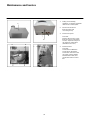
Maintenance Checks and Inspections ................................................. 32
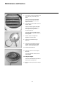
Maintenance and Service ....................................................................................... 34
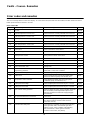
Faults, Causes, Remedies Error codes and remedies .............................................. 36
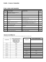
Sensor Resistances........................................................ 37
Electrical diagram ........................................................... 38
Declaration of coonformity .............................................. 39
2

General Information
General Information
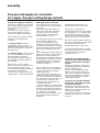
Installation, erection, power
connection and first start-up are
duties of a qualified person who is
responsible for proper completion of
these tasks.
Notes for the operating company
Both the safety and function of the
Thermo unit remain ensured if the
plant is regularly serviced by a
heating specialist. To ensure regular
scheduling it is recommended to
conclude a servicing agreement.
To operate the unit in a user-friendly
and stable way, we recommend also
building in the unit base included in
the options.
Prior to the installation of the
THISION S Thermo unit, first
obtain the approval of the gas
supply company and of the district
chimney sweeper.
Explanations to our warranty
terms
We do not grant warranty for
damages caused for the following
reasons:
- improper or inappropriate use or
operation or misuse
- faulty assembly or start-up by Buyer
or Third parties
- incorporation of parts from external
origin
- operating the plant with excess
pressure or outside the tolerances
specified by the works
- use of inappropriate combustibles
- non-observance of the notes in the
Operating Instructions and
indications printed on the attached
labels on the Thermo unit
Regulations
You should adhere to the following
standards to ensure safe and non-
polluting and energy-saving
operation:
DIN 1988
- Drinking water supply systems
plants on land sites, technical
regulations for construction and
operation
90/396/EWG
- EU Guidelines for
gas appliances
92/42/EWG
- EU Guidelines for energy efficiency
97/23/EWG
- EU Guidelines for pressure
equipment
EN 437
- EU Guideline test gases - test
pressures – product groups
EN 483
- Boilers for gaseous fuels
EN 677
- Central heating boilers for gaseous
fuels
EN 60335-1
Household and similar electrical
appliances - Safety - Part 1: General
requirements
EN 50165
Electrical equipment of non-electric
appliances for household and similar
purposes - Safety requirements
DIN V-18160-1
- Chimney, planning and execution
DIN EN 12831
- Rules for the calculation of heat
quantities required in buildings
DIN EN 12828
- Safety equipment of heating
systems with admission
temperatures up to 95°C
For Germany also applicable:
- EnEV
Energy Saving Ordinance
- TRGI (DVGW G600)
Technical regulations, gas
Installation
- ATV DVWK-A251
Introduction of condensate from
burner units into public sewage
systems
- Land building regulations TRF
Technical regulations, liquefied gas
- DVGW G688
Thermo unit technology
“Arbeitsblatt
For Austria also applicable:
- ÖNORM H 5152
Thermo unit burner systems,
Planning aids
- ÖNORM M 7443
Gas units with atmospheric burner
Part 1, 3, 5, 7
- ÖNORM M 7457
Gas units with mechanically
supported premix burner
- ÖNORM H 5195-1
heating water norm
- ÖVGW Directives
G1 Technical Directive for the
installation of low-pressure gas
systems
G2 Technical Directive for the
installation of liquefied gas systems
G41 Gas Thermo burner units,
installation and connection
G4 Heating room directive
- The unit is approved under Article
15a B-VG and under the burner
system Act VO (FAV 97)
- Always adhere to communal
building regulations
For Switzerland also applicable:
- GebäudeKlima Schweiz
Swiss association for heating,
ventilation and air conditioning
technology
- SVGW gas guidelines G1:
Gas installations Swiss.
Association of Gas and Water
Professions
- EKAS - Form, 1942:
Liquid Gas Guidelines, Part 2
- BAFU
Federal Office for the Environment
- VKF
Association of Cantonal Fire
Insurances
- SWKI
Swiss Society of HVAC Engineers
For Belgium also applicable:
- NBN D51-003
Also adhere to all relevant national
regulations and standards.
3

Heating Water Quality
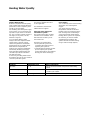
Heating Water Quality
Both the composition and the quality
of the system water directly affect the
performance of the complete system
and life cycle of the boiler.
For first filling and subsequent supply
to the system, you can generally use
tap water of a pH value of 7-8 unless
it is very corrosive (chloride content >
150 mg/L) or very hard (> 14°dH;
hardness range IV).
You can obtain drinking water
analyses from the competent water
supply works. If specific system
volume is higher than 20 litres/kW
heating power (if any heating water
buffer tank is incorporated, for
instance), the maximum admissible
lime feed by the filling and supply
water should be determined by the
calculation procedure indicated in
VDI Directive 2035.
If necessary, the filling water should
be softened. Do not use any chemical
corrosion protection agents.
For Austria, ÖNORM H 5195-1
is also applicable.
For Switzerland, the directive
SWKI BT102-01 applies.
Unknown water quality and
substitution systems
The heating water often contains
substances and additives which
affect function and life cycle of
the Thermo unit.
Therefore you should either:
heat up the old system and
completely discharge it prior to
replacing the system or
carefully flush the heating system
prior to replacing the system.
System flush will be most efficient
directly prior to first heating up.
Floor heating
You can directly connect floor heating
when pipes are sealed against
oxygen.
You usually have to build in a
temperature controller for the floor
heating system to prevent the pipes/
floor coverings from overheating. If
you do not know the model of floor
heating (when systems are replaced,
for instance) you have to install a
separating device between the
systems of boiler and floor heating
using a heat exchanger (option).
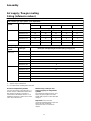
Criterion
Admissible value
Effect of deviations
pH value
7 - 8
Risk of corrosion for boiler components and heating
system
Hardness degrees
< 14 dH / < 25 fH
- increased lime depositing
- low life cycle of boiler
Chloride content
< 150 mg/l
Corrosion of alloy materials
4

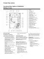
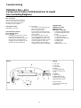
Product Description
Functional Description of THISION S
Delivery Scope
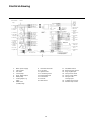
Legend:
1 Gas connection
2 Gas valve
3 Gas burner
4 Flue gas connection
5 Flue gas STL 100° C
6 Heating flow
7 Boiler supply STL 100° C
8 Heating return
9 Return line sensor
10 Ignition transformer 230 V
11 Fan 230 V
12 Heat exchanger / condenser
13 Flame inspection hole
14 Operator panel with LMU
microprocessor
15 Energy saving pump
16 Automatic vent
17 Water pressure monitor
18 Fill and drain valve
19 Safety valve 3 bar
20 Safety valve outlet
21 Siphon
22 Siphon outlet
23 Analogue Manometer
24 Hot water return flow connection
Product Description
The THISION S is a wall-hung
condensing and modulating gas
condensing boiler with a premix burner.
It has the following unique features:
- a large modulation range ensures
long burner on times, minimises
standby losses, start-up emissions,
and material stress.
- flue gas temperature below 80°C
- flue gas temperature fuse
- also suitable for balanced flue
operation
- device control panel with all control
elements
- microprocessor with multi-function
display
- automatic ignition with repetition and
ionisation control
- water shortage protection device
- analogue manometer
- energy saving pump
- built-in safety valve
- stainless steel - heat exchanger with
ribbed tube condenser
- storage tank loading function
- extremely easy to maintain
- weather-driven control with QAA 75
remote control (optional)
- modern, thermocoated metal
housing
Functional description
Using default values, the controller
adjusts by changing the fan speed heat
output to the actual heat demand of the
heating system. To do this, the boiler
supply temperature is continuously
measured via a sensor.
If there is a deviation in the actual
temperature from the desired
temperature, the control immediately
responds and adjusts the speed of the
fan, and thus - via the gas valve- the
boiler output also.
A deviation may result from:
- changing the boiler temperature
default value on the LOGON B
heating controller
- change in outside temperature
- hot water requirement
- change in heating curve
- change in heating system volume
flow (from thermostatic valves and
mixers)
The individual components working as a
system ensure that the boiler output
always meets the actual heat demand -
within the control range of the device.
Consignment
The boiler is factory assembled and
ready for operation, and is delivered in a
cardboard box.
Included with the THISION S are:
- mounting rail (included in
packaging)
- operating manual
- QAA 75 room temperature
controller (optional) (unit packed
separately)
- outdoor sensor (unit packed
separately)
5

Product Description
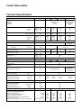
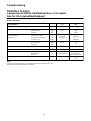
Technical Specifications
Type THISION S
9.1
13.1
17.1
25.1
CE Approval
Category
SVGW No.
CE0085AT0244
DE-I2LL/AT-I2H
09-027-4
CE0085AQ0543
DE-II2ELL3B/P/
AT-II2H3B/P
ÖVGW No.
G2.777
09-027-4
G2777
Output Full load
80/60°C kW
9,1
13,3
16,9
23,9
40/30°C kW
9,9
14,6
18,3
25,7
Minimum
80/60°C kW
1,0
2,3
2,3
4,8
Load
40/30°C kW
1,2
2,7
2,7
5,4
Rated thermal input Full load
kW
9,3
13,9
17,4
24,5
Minimum load
kW
1,1
2,5
2,5
5,0
Boiler efficiency Full load
80/60°C %
97,8
97,4
97,4
97,4
40/30°C %
106,5
105,0
105,0
105,0
Minimum
80/60°C %
95,0
96,3
96,3
97,3
Load
40/30°C %
108,5
108,5
108,5
108,5
Efficiency factor
%
108,5
Gas type
Natural gas
Natural gas or
liquid gas
CO2 Natural gas min./max.
Vol. %
8,5 / 9,5
8,5 / 9,5
Flüssiggas min./max.
Vol. %
10,5 / 10,5
NOX min./max.
Annual emissions value
(3%O2) mg/m3
(3%O2) mg/m3
25/40
30
50/50
50
10/30
14
10/40
16
CO min./max.
Annual emissions value
(3%O2) mg/m3
(3%O2) mg/m3
0/10
3
0/15
5
0/20
6
0/30
10
Standby losses
Tk 70°C W
150
Tk 40°C W
85
Max. flue gas temperature
80/60°C
58 - 67
Flue gas mass flow max.
kg/h
15
20
26
39
Max. residual flue gas pressure
Pa
100
Water capacity
l
3,2
Weight
kg
52
Norm. gas flow pressure
mbar
20 Natural gas
20 Natural gas /
50 liquid gas
Min./max. gas flow pressure
mbar
17,4/25 Natural gas
17,4/25 Natural gas
/
50 liquid gas
Heating operating pressure min./max.
bar
1 - 3
Operating temperature max.
°C
90
Voltage/Frequency
Volt/Hz
230 VAC / 50 Hz
Boiler power consumption min./max.
W
18 / 37 18 / 37 18 / 37 18 / 34
Pump power consumption min./max.
W
8 / 36 8 / 36 11 / 50 10 / 49
Width / Depth / Height
mm
540 / 361 / 760
Male threaded gas connection
R
1”
Male threaded flow/return
R
1”
PPS flue gas connection nominal width
DN
80
Supply air connection inside
Ø mm
125
PVC condensate connection outside
Ø mm
32
Sound pressure level at a distance of 1m
dB(A)
39 - 53
40 - 51
Product information for system energy efficiency
in accordance with DIN V4701-10:
Nominal heating capacity
Efficiency at nominal heating capacity
Part load combustion efficiency
Qn (kW)
η100% (%)
η30% (%)
9,1
98,3
108,5
13,5
97,4
108,5
16,6
97,4
108,5
23,9
97,4
108,5
Return line temp. with 30% part load efficiency
Standby mode heat loss
T 30% (C)
q B,70 (%)
30
1,61
30
1,08
30
0,88
30
0,61
Aux. Power supply: Boiler incl. Heating circuit pump
min./max.PHE (W)
26 / 73
26 / 73
29 / 87
28 / 83
6

Product Description
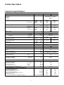
Technical Specifications
Typ THISION S
35.1
50.1
CE Approval
Category
SVGW No.
ÖVGW No.
CE0085AR0323
DE-II2Ell3B/P / AT-II2H3B/P
09-027-4
G2.777
Output
Full load
Minimum load
80/60°C
40/30°C
80/60°C
40/30°C
kW
kW
kW
kW
34,1
36,8
9,7
10,8
48,7
52,5
9,7
10,8
Rated thermal input
Full load
Minimum load
kW
kW
35,0
10,0
50,0
10,0
Boiler efficiency
Full load
Minimum load
80/60°C
40/30°C
80/60°C
40/30°C
%
%
%
%
97,3
105,0
97,3
107,7
97,3
105,0
97,3
107,7
Efficiency factor
%
108,2
Gas type
Natural gas or Liquid gas
CO2 Natural gas
Liquid gas
min./max.
min./max.
Vol. %
Vol. %
8,5 / 9,5
10,5 / 10,5
NOX
Annual emissions value
min./max.
(3%O2)
(3%O2)
mg/m3
mg/m3
30/35
31
30/55
36
CO
Annual emissions value
min./max.
(3%O2)
(3%O2)
mg/m3
mg/m3
0/10
3
0/25
8
Standby losses
Tk 70°C
Tk 40°C
W
W
150
85
Max. flue gas temperature
80/60°C
58 - 67
Flue gas mass flow
max.
kg/h
54
77
Max. residual flue gas pressure
Pa
100
Water capacity
Weight
l
kg
4,0
62
Norm. gas flow pressure
Min./max. gas flow pressure
mbar
mbar
20 Natural gas / 50 Liquid gas
17,4/25 Natural gas / 50 Liquid gas
Heating operating pressure
Operating temperature
min./max
. max.
bar
°C
1 - 3
90
Voltage/Frequency
Boiler power consumption
Pump power consumption
min. / max.
min. / max.
Volt/Hz
W
W
230 VAC / 50 Hz
19 / 47
10 / 70
Width / Depth / Height
mm
765 / 361 / 760
Male threaded gas connection
Male threaded flow/return
PPS flue gas connection
Supply air connection
PVC condensate connection
nom. width
inside
outside
R
R
DN
Ø mm
Ø mm
1”
1”
80
125
32
Sound pressure level at a distance of 1m
dB(A)
40 - 51
Product information for system energy efficiency in
accordance with DIN V4701-10:
Nominal heating capacity
Efficiency at nominal heating capacity
Part load combustion efficiency
Return line temp. with 30% part load efficiency
Standby mode heat loss
Aux. Power supply: Boiler incl. Heating circuit pump
min. / max.
Qn (kW)
η100% (%)
η30% (%)
T30% (C)
q B,70 (%)
PHE (W)
34,1
97,3
107,7
30
0,54
29 / 117
48,7
97,3
107,7
30
0,38
29 / 117
7

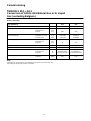
Product Description
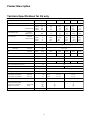
Technical Specifications for CH only
nur für CH
Type THISION S
10.1
21.1
30.1
40.1
45.1
Approval SVGW - No.
09-027-4
Output Full load
Minimum load
80/60°C kW
40/30°C kW
80/60°C kW
40/30°C kW
9,6
10,6
2,3
2,7
20,5
22,1
4,8
5,4
29,2
31,5
9,7
10,8
38,9
42,0
9,7
10,8
43,8
47,3
9,7
10,8
Rated thermal input Full load
Minimum load
kW
kW
10,0
2,5
21,0
5,0
30,0
10,0
40,0
10,0
45,0
10,0
Boiler efficiency Full load
Minimum load
80/60°C %
40/30°C %
80/60°C %
40/30°C %
97,4
106,0
96,3
107,7
97,4
105,0
97,3
107,7
97,3
105,0
97,3
107,7
97,3
105,0
97,3
107,7
97,3
105,0
97,3
107,7
Efficiency factor
%
108,5
108,2
Gas type
Natural gas or liquid gas
CO2 Natural gas min./max.
Liquid gas min./max.
Vol. %
Vol. %
8,5 / 9,5
10,5 / 10,5
NOX min./max.
(3%O2) mg/m3
10/35
10/35
30/30
30/35
30/40
CO min./max.
(3%O2) mg/m3
0/25
0/25
0/10
0/15
0/20
Standby losses
Tk 70°C W
150
190
Max. flue gas temperature
80/60°
58 - 67
60 - 68
Flue gas mass flow max.
kg/h
16
33
46
62
69
Max. residual flue gas pressure
Pa
100
Water capacity
l
3,2
4,0
Norm. gas flow pressure
mbar
20 Natural gas / 50 Liquid gas
Heating operating pressure min./max.
bar
1 - 3
Voltage/Frequency
Boiler power consumption min./max.
Pump power consumption min./max.
Volt/H
z W
W
230 VAC / 50 Hz
18 / 37 18 / 34
8 / 36 10 / 49
230 VAC / 50 Hz
19 / 47
10 / 70
Width / Depth / Height
mm
540 / 361 / 760
765 / 361 / 760
Male threaded gas connection
Male threaded flow/return
PPS flue gas connection Nom. width
Supply air connection inside
R
R
DN
Ø
mm
1”
1”
80
12
5
1”
1”
80
12
5
Sound pressure level at a distance of 1m
dB(A)
40 - 51
8

Product Description
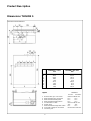
Dimensions THISION S
Dimensional Sheet THISION S
THISION S 9.1-25.1
mm
THISION S 35.1+50.1
mm
A
96,5
141,5
B
313,5
414,5
C
540,0
765,0
D
148,1
197,0
E
42,0
27,0
F
217,1
358,5
G
80,4
67,5
H
100,0
82,5
J
85,0
150,0
1 External flue gas connection Ø 80 mm Ø 80 mm
2 Male threaded gas connection R 1” R 1”
3 Male threaded heating flow R 1“ R 1“
4 Male threaded heating return R 1“ R 1“
5 Condensation outlet Ø 32 mm Ø 32 mm
6 Safety valve 3/4" 3/4"
7 Male threaded storage tank return R 1” R 1”
8 Concentric supply air connection Ø 125 mm Ø 125 mm
9 Mounting rail
Legend:
9.1-25.1 35.1+50.1
THISION S
9

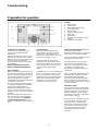
Product Description
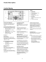
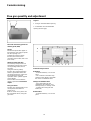
Control Display
A
M
H
B C D E F
G
L
I
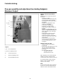
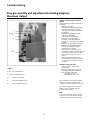
Operation mode DHW (M)
For switching on the DHW operation
(indication in display below DHW
symbol)
Operation mode heating zone(s) (I)
For setting 4 different heating modes:
Auto (clock): Automatic operation
by time programm
Comfort (sun): 24/7 heating in
comfort mode
Reduction (moon): 24/7 heating in
reduced mode
Standby: heating off, frost
protection activated.
Display (L)
Info mode (G)
Display possibility of following info
without influence on boiler control:
temperatures, operation mode Heating
/ DHW, error code.
Room temperature control (C)
for changing room comfort
temperature
for changing setting when
programming.
On/off switch (A)
Position 0:
Boiler and connected electrical
components are not powered. Frost
protection is not secured.
Position I:
The boiler and connected electrical
components are powered and standby
for operation.
Confirmation (OK) (D)
Return (ESC) (B)
These buttons are used for program-
ming in combination with the rotary
knob.
By pressing the ESC button it‘s
possible to go back one level,
changed values are not taken over by
the controller.
By pressing the OK button it‘s
possible to arrive in the next level or
confirm changed values.
Manual mode (E)
This button is used for switching the
boiler into manual mode. In manual
mode all pumps will run and the
mixing valves are no longer controlled,
the burner setpoint is 60°C (indicated
by spanner symbol).
In the display, the „tool“ symbol is
shown. This manual mode should be
used as a temporary measure to
assure proper functioning of the boiler
in case of a disfunctional controller or
wrong settings, and should in no case
be applied for a longer period.
Deaeration mode (E)
By pressing the manual mode button
longer than 3 seconds, the automatic
hydraulic deaeration is activated e.g.
after first filling the system. During
deaeration, the system is switched to
the protection mode . The pumps are
switched on and off for several times.
After deaeration, the boiler
automatically returns to normal
operation.
Legend:
A On/off switch
B Return (ESC)
C Room temperature control
D Confirmation (OK)
E Manual mode
F Chimney sweeper mode
G Info mode
H Reset button
I Operation mode heating zone(s)
L Display
M Operation mode DHW
Chimney sweeper mode (F)
Used for combustion analysis. By
pressing the button once again, or
automatically after 15 minutes, the
chimney sweeper mode will be
deactivated (indicated by spanner
symbol).
In case a mixing circuit is part of the
heating system, the control continues
normally.
Reset Button (H)
By shortly pressing the reset button a
burner lockout can be cancelled.
Notes
a After pressing reset once, wait for
ca. 20 seconds (LMU initialising,
error code 132 shows briefly; Gas
flow control input is checked).
b When pressing reset twice, the
LMU controller is locked manually
(error code 153).
Press reset again.
c Pressing reset without error
code triggers error code 153
10

Hydraulics
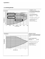
Circulating pumps
THISION® S 9.1-25.1
The boiler surface pump is factory
set to continuous operation, so that
the speed is adjusted according to
the heat demand.
Technical Specifications
UPM2 15-70 CIAO 1 x 230V
Output (W) 63 - 4
Energy Efficiency Index EEI < 0,23
1 Circulating pump range and
available pump pressure
2 Boiler resistance
3 Pump curves (full load)
THISION® S 35.1-50.1
The boiler circuit pump is factory set to
operate at a constant speed, and the
installer can set it to the desired lifting
height.
Technical Specifications
UPM2 15-70 AOS 1 x 230V
Output (W) 70 - 10
Energy Efficiency Index EEI < 0,23
1 Circulating pump range and
available pump pressure
2 Boiler resistance
3 Pump curve (full load)
11
Pump diagram
Pressure Head (m)
Pressure Head (m)
Pump diagram
Flow rate (m3/h)
Flow rate (m3/h)
2. Boiler resistance
3. Pump curves
1. Pump range

Hydraulics
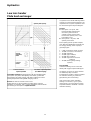
Low loss header
Plate heat exchanger
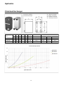
Calculation example: Heating with 16° dH (28° fH) filling water,
new system (10 years) with optically clear water, system with
floor heating (25 l plant capacity / kW boiler output) and a max.
heating temperature during DHW charging of 90° C.
Result: The low loss header can be used.
Safety devices are to be installed according to the relevant
guidelines. In particular, with a system separation, both the boiler
and heating circuit require an expansion tank.
Low loss header or
Low loss
header
System-
separation,
PLHE
System separation
Water härdness
Specific plant capacity
max. boiler output temperature
(incl. DHW-charging)
In systems of over 40 kW with large water
capacity or increased water hardness, the
requirement for a system separation must
be checked using the adjacent diagram.
Legend:
A Old system > 15 years, with
heavily polluted heating water.
Once the system has been
carefully rinsed, and the water
has become optically clear, curve
B should be used.
B New system < 15 years, with
optically clean water
Plant capacity per kW system example;
note: with large distribution networks and
low energy housing, water capacity is
generally higher:
1 5 l/kW (ventilation, DHW-System)
2 10 l/kW (convectors, fan heaters)
3 15 l/kW (radiators)
4 20 l/kW (pipe-radiators)
5 25 l/kW (floor heating)
6 30 l/kW (high volume cast iron
radiators)
7 35 l/kW (olders gravity heating-
systems)
Floor heating
Underfloor heating can be connected
directly with oxygen-impermeable pipes.
It is always necessary to check whether
an additional pump is needed.
A temperature monitor is always installed
for underfloor heating, to protect the
pipes/flooring from overheating.
If the construction of the underfloor
heating is not known (e.g. for system
replacement), you must install a system
separation between THISION S and the
underfloor heating.
12

Hydraulics
Low Loss Header
Dimension drawing
Low loss header
V1
R1
2
1
h1
4
B
h2
h3
3
V2
R2
Legend
1 Deaeration valve connection
2 1/2" temperature sensor sleeve
3 Sleeve
4 Fill and drain valve connection
V1 Heat generator flow
V2 Heat consumer flow
R1 Heat generator return
R2 Heat consumer return
Chamber size
Female thread
Dimensions in mm
Recommended flow rate
mm
V1 / V2 / R1 / R2
B
h1
h2
h3
max
bis
bei
(with insulation)
60x60
Rp 1"
146
280
340
450
3,0 m3/h
26 kW
T 7,5 °C
(100x100)
35 kW
T 10 °C
52 kW
T 15 °C
69 kW
T 20 °C
60x60
Rp 1 1/4"
156
280
340
450
4,0 m3/h
35 kW
T 7,5 °C
(100x100)
46 kW
T 10 °C
69 kW
T 15 °C
93 kW
T 20 °C
80x80
Rp 1 1/2"
176
470
540
700
7,0 m3/h
50 kW
T 7,5 °C
(125x125)
81 kW
T 10 °C
122 kW
T 15 °C
162 kW
T 20 °C
80x80
Rp 2"
192
470
540
700
9,0 m3/h
78 kW
T 7,5 °C
(125x125)
100 kW
T 10 °C
157 kW
T 15 °C
209 kW
T 20 °C
The pressure loss in the low loss header is insignificant and can be neglected.
13

Hydraulics
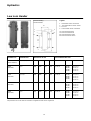
Plate Heat Exchanger
Type x number
Plates
a
b
c
d
L
Weight
S1 ... S4
Recommended layout
mm
mm
mm
mm
mm
kg
Male thread
max. m3/h
dP (kPa)
kW at dt 10K
BX8TH x 52
315
73
278
40
121
4,3
G 3/4“
2,15
10,5
25
B10TH x 56
289
119
243
72
135
6,8
G 1“
4,30
11,0
50
B16H x 124
376
119
320
63
288
16,6
G 11/4“
8,60
10,8
100
Dimension drawing
Plate heat exchanger
S1 = Boiler circuit flow
S2 = Boiler circuit return
S3 = Heating circuit flow
S4 = Heating circuit return
Pressure loss in kPa
25
20
15
10
0
5
0,5 1,5 2,5 3,5 4,5 5,5 6,5 7,5
Flow rate in m3/h
Pressure drop curves
BX8THx52
B10THx56
B16THx124
14

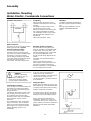
Assembly
Installation, Mounting
Water, Electric, Condensate Connections
Water connection
The boiler can be used for all hot water
heating systems with a system
pressure of at least 1.0 bar.
You must observe the safety
regulations. Prior to commissioning,
you must check that the heating supply
and return is connected correctly.
Use the fittings supplied for the water
connection. When removing the plastic
caps from the water-carrying
connections, test water may leak out.
Positioning
Always position the device so that
operation and maintenance are easily
possible.
The distance from the wall on each
side must be at least 10 mm.
Minimum clearance to the front is 800
mm (cabinet installation excluded).
The installation location must comply
with the applicable guidelines and
regulations.
Surface temperatures < 85°C.
Electrical System Connection
Der The boiler is factory-wired and
ready for operation, and equipped with
a 230V 50Hz connecting cable. The
electrical installation must comply with
the relevant STANDARD or the
specific overall wiring diagram for the
system.
The boiler must be protected with a
10 A fuse.
Phase and neutral must not be
interchanged, or the boiler will cut out.
The unit is not water resistant and
therefore installation is only permitted
in a non-splash-prone location.
Mounting
The boiler is attached horizontally to
the wall, using the supplied mounting
rail.
If the three pre-drilled holes are not
suitable, drill additional suitable
holes.
Installation und Distances
THISION S
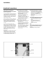
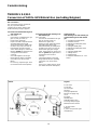
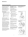
Condensate connection
0.7 to 1.0 litres of condensate water are
generated per m3 of burned natural
gas, as a result of the extremely high
energy efficiency.
Condensate arising in the boiler, in the
flue gas pipe and in the chimney is to
be conducted away into the public
drainage system. Here, the regulations
of the particular country must be
observed.
The neutralisation of the condensate
may be necessary. The condensate
must run out clearly visible through a
funnel siphon (2). A fixed connection
with the drainage system is not
permissible.
Only non-corrosive and approved
materials are to be used for the
condensate drainpipe. The discharge is
carried out in a frost-free room.
Lay the drain with a gradient in order to
avoid backflow.
Filling the siphon
Before taking the boiler into service, the
boiler-siphon (1) is to be filled with water
in order to prevent flue gases escaping
from the condensate connection.
The easiest way to fill ist to pour about
0.5 liter of water in the flue gas pipe (3).
Otherwise unscrew the siphon to fill it.
During servicing and maintenance
inspections, at least once a year, the
condensate drain is to be cleaned , the
siphon and flue connections checked for
tightness and the boiler-siphon filled
with water.
DANGER:
Danger of poisoning!
If the siphon (1) is not
full of water, or with open
connections, flue gases arising
can put people in mortal danger.
2
3
1
15

Assembly
Flue gas and supply air connection
Air supply / flue gas routing design variants
Flue gas and supply air connection
The boiler is suitable for open flue and
balanced flue operation. The flue gas
pipe must be disassembled for
connection.
For all flue gas systems you must
ensure that no bypass is present
between the supply air and flue gas.
Pipe extenders may only be installed
vertically to avoid condensate
formation.
For flue gas safety the boiler is
equipped with a flue gas safety
temperature limiter (STL) (set at 100°C)
which does not therefore need to be
provided on-site.
The fresh air supply must be ensured.
This is to be installed in accordance
with applicable gas guidelines.
Local regulations must be observed.
We generally recommend balanced
flue operation.
Often there is a risk of corrosive
vapours, especially in laundry or work
areas, hairdressing salons, and in
rooms where electroplating, printing or
metalworking is taking place.
In such cases, the supply air must be
supplied from a suitable point outdoors.
Air/flue gas routing connection
Only original ELCO accessory parts
may be used for the concentric air/flue
gas routing.
Clearance between the air/flue gas
routing and combustible materials is
not required, because at nominal
heating capacity no temperatures
higher than 80°C can occur.
The air/flue gas routing must not be fed
through other installation sites.
If gas condensing appliances are
installed as externally wall mounted
units (air/flue gas routing on outer wall),
the nominal heating capacity in heating
mode must be reduced to below 11
kW.
If the combustion forced air supply and
air/flue gas control lines are enclosed
within the floors of the building, the
lines outside the installation room must
be fed through a shaft with a minimum
90 minute fire resistance, and less in
residential buildings, of minimum 30
minute fire resistance.
If the gas appliances are installed in
rooms, in which only the roof structure
is above the ceiling, the following
requirements apply:
- If fire resistance is required for the
ceiling, the combustion air and gas flue
lines in the area between the upper of
the ceiling edge and roof must have an
enclosure panel, of the same fire
resistance value, and made of non-
combustible materials.
- If no fire resistance is required for the
ceiling, the combustion air and gas flue
lines in the area between the upper of
the ceiling edge and roof must be laid
in a shaft of non-combustible,
dimensionally stable materials, or in a
metal protective tube (mechanical
protection).
Exhaust pipes must be able to be
checked on their free cross section.
At least one a corresponding
audit/inspection hole is to be provided in
the installation site, in consultation with
the competent local master chimney
sweep. Flue gas connections must be
made gases using sleeves and seals.
Sleeves are always installed against the
direction of condensate flow. The air/flue
gas routing must be fitted to the
condensing boiler at a 1-3 % incline.
To avoid mutual interference in air/flue
gas routing on the roof, we recommend
a minimum air/flue gas routing
separation of 2.5 m.
Connection to moisture-resistant
air/exhaust flues (exhaust/supply air
system), exhaust flues, or flue gas
systems
Chimneys and exhaust systems must
be officially approved for condensing
furnaces (DIBt approval).
Sizing is done using the calculation
tables, according to the exhaust gas
value group. A maximum of three 90°
bends may be installed. For chimneys,
a working pressure of 0 Pa is to be
used in the calculation.
Connection to a moisture-resistant
exhaust flue or B23 exhaust system
for open flue operation
The air/flue gas routing must not be
longer than 2 m when installed on an
exhaust flue. A maximum of three 90°
bends may be installed.
The exhaust flue must be checked by
the DIBT and approved for condensing
operation.
16

Assembly
Air supply / flue gas routing
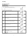
Sizing (reference values)
D 80 / 100 flue gas pipe systems (room dependent)
Flue gas
system
Boiler type
Flow direction changes
2
3
4
5
6
Total pipe length in metres (flue gas)
D 80
THISION S 9.1
32
29
26
23
20
THISION S 13.1
29
26
23
20
17
THISION S 17.1
25
22
19
16
13
THISION S 25.1
15
12
9
6
3
D 100
THISION S 35.1
26
24
22
20
18
THISION S 50.1
20
18
16
14
12
Flue gas/supply air system, D 80/125 and D 110/150 balanced flue (room air independent)
Flue gas
system
Boiler type
Riser pipe total pipe length in metres (flue gas/supply air)
D 80 / 125
THISION S 9.1
9
THISION S 13.1
12
THISION S 17.1
15
THISION S 21.1*
13
THISION S 25.1
12
THISION S 35.1
8
D 110 / 150**
THISION S 25.1
15
THISION S 30.1*
15
THISION S 35.1
15
THISION S 40.1*
12
THISION S 45.1*
12
THISION S 50.1
12
*) applies only to Switzerland
**) for Switzerland and Belgium Ø 100/150
Room air independent operation
For each 90°change in flow direction, 1.5
metres must be subtracted from the total
pipe length. The boiler connection is
carried out for all D80/125 devices. The
additional resistance is taken into account
in the above dimensions.
17
Dimensioning of flue gas and
supply air piping for single boiler
systems.
The maximum possible flue gas and
supply air pipe lengths (max. total
length) with respect to x flow direction
changes.
Important:
Please note the
comments regarding the flue gas and
supply air and condensate
connections in the Connections
chapter.

Assembly
Air supply / flue Gas
Routing Design
Variants
Ambient air dependent, ø80 PP
B23
Exhaust gas connection to exhaust gas system
Multiple assignment (negative pressure /overpressure)
Ambient air independent, ø 80/125 PP/Steel plate
18
C13
C13x
Air/exhaust gas routing through outside wall in the same pressure
range
C33
C33x
Air/exhaust gas routing via the roof in the same pressure range.
Flue gas outlet vertical endpiece.
C43
C43x
Air intake and flue gas outlet via a chimney system, integrated
within the building.
C53
C53x
Fresh air supply and exhaust gas routing to the exterior in various
pressure ranges. Flue gas outlet vertical endpiece.
C63*
C63x
Specially designed for connection to approved separate supply
air/flue gas systems devices.
C83
C83x
Air intake outside the building, flue gas outlet in chimney.
C93
C93x
Air/flue gas routing to exhaust flue above roof installation in damp
resistant exhaust flue.
min. ring clearances for exhaust pipes:
Ø80 = 45mm
Ø100 = 50mm
Ø110 = 40mm
*) Not permitted for Belgium

Installation
Electrical Connections
NOTE: Before performing any
procedures, you must ensure that the
device is switched off.
To ensure greater security, the electrical
system should be carefully checked by a
qualified technician. The manufacturer is
not liable for any injury caused by a lack
of earthing conductor or due to faulty or
defective power supply.
Make sure that the system is suitable for
the maximum power consumption of the
heater, as specified on the type plate.
Check that there is adequate cable
cross-section, or that it is no less than
1.5 mm2.
In order to ensure the safety of the
device, correct connection to an efficient
earthing system is essential. The heater
is supplied with power cable but no plug.
The power cable must be connected to
a 230 V - 50 Hz network, where LN
polarity and grounding must be taken
into account.
Important! The connection to the mains
supply must be via a fixed connection
(not with removable plug), which must
be equipped with a two-pole switch with
a contact opening of at least 3 mm.
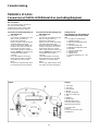
QAC34 external sensor (X10-06)
- The outdoor sensor is connected
using a cable of at least 2x 0.5 mm2.
In this way, a maximum length of
50 m is ensured.
- The sensor should ideally be
positioned at a height of 2 - 2.5m
above ground, and aligned
northwards. In all cases, it must not
be directly exposed to sunlight.
- Connect the outdoor sensor to the
following connector: X10-06.
QAA75 remote control (X16)
- Remove the 4 screws "C" from the
PCB cover "D".
- The remote control is connected
using a cable of at least 2x0.5 mm2:
In this way, a maximum length of
50 m is ensured.
- The remote control BUS cable (20-
30 V) must be installed separately
from the 230 V/50 Hz cables.
- Connect to the remote control to
connector X16.
Room thermostat (X10-01 or X10-02)
The thermostat must be attached to
the electronic circuit board using the
following connectors: X10-01 for room
thermostat 2 or X10-02 for room
thermostat 1.
Remove jumper only to connect the
thermostat.
Floor heating safety thermostat (X3-01)
The safety thermostat for the floor
heating is connected to connector
X3-01.
When triggered, the device is
completely switched off and lock
(reset).
Remove the jumper.
Note
The connection cable between the board
and the peripherals (QAA75, QAC34 as
well as the room thermostat) must be
shielded.
The shielding must be grounded.
X3-01
X16
X10-01
X10-02
X10-06
19

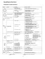
Operating instructions
Overview of main functions
Button
Action
Procedure
Display / Function
Set room temperature
Zone 1 and zone 2
Actuate rotary knob
left/right Turn rotary knob
Confirm with OK button or
wait 5 sec.
or press
Comfort setpoint with blinking temperature
Blinking temperature in 0,5 °C steps from 10 to 30 °C
Comfort setpoint saved Comfort
setpoint cancelled
- after 3 sec. Main menu appears
Set room temperature
for zone 1 or zone 2
Zone 2 independent from zone 1
Actuate rotary knob left/right
Confirm with OK button
Actuate rotary knob left/right
Confirm with OK button or
wait 5 sec.
or press
Choose heating zone
Heating zone is chosen
Blinking temperature in 0,5 °C steps from 10 to 30 °C
Comfort setpoint saved Comfort
setpoint cancelled
- after 3 sec. Main menu appears
Switch on /off DHW
operation
Press button
DHW mode on / off
(see indication below DHW symbol) -
On: DHW mode by time programm -
Off: no DHW operation
- Safety functions activated
Change heating
operation mode
Factory setting
Press button 1x Press
button 1x again
Press button 1x again
Automatic mode on, with:
- Heating by time programm
- Temperature setpoint by heating programm
- Safety functions activated
- Summer/Winter automatic switching activated
- ECO-functions activated
(see indication below operation symbol)
Continuous COMFORT heating on, with:
- Heating without time programm by comfort setpoint
- Safety functions activated
Continuous REDUCED heating on, with:
- Heating without time programm by reduced setpoint
- Safety functions activated
- Summer/Winter automatic switching activated
- ECO-functions activated
Safety mode on, with:
- Heating off
- Temperature by frost protection
- Safety functions activated
Controller Stop mode Press button > 3 sec. Press
button > 3 sec. again
304: Controller Stopp mode insert setpoint
after 3 sec. Main menu appears
Info display
Press button 1x Press
button 1x again Press
button 1x again .....
Press button 1x
INFO Segment displayed
- Status Boiler - room temperature
- room temperature minimum
- Status DHW - room temperature maximum
- Status zone 1 - outside temperature
- Status zone 2 - outside temperature minimum
- outside temperature maximum
- Time / Date - DHW temperature 1
- Error indication - Boiler temperature
- Maintenance indication - Flow temperature
(Info display depends on configuration)
Back to main menu; INFO Segment disappears
Operation by manual
setpoint
Change factory setting
boiler temperature
Press button 1x
Press button
Press button
Turn rotary knob -/+
Press button
Press button
Press button
Manual mode on
(spanner symbol appears)
- Haeting by fixed setpoint
(factory setting = 60 °C)
301: Manual mode insert setpoint?
blinking temperature set value
Status boiler
Manual mode off (spanner symbol disappears)
Deaeration Press button > 3 sec. Press
button > 3 sec. again
312: Deaeration on
Deaeration off
Activate chimney
sweeper mode
Press button (< 3 sec.) Press
button again (< 3 sec.)
Chimney sweeper mode on
Chimney sweeper mode off
Temporary reduction of
reduced temperature on
QAA75
Press button Press
button again Heating by reduced setpoint
Heating by comfort setpoint
RESET
Reset button Press button (< 3 sec.)
Press button again > 3 sec.
Boiler manually blocked, no release
Boiler released, Alarm symbol disappears
= confirmation = cancel, return to main menu
20
Page is loading ...
Page is loading ...
Page is loading ...
Page is loading ...
Page is loading ...
Page is loading ...
Page is loading ...
Page is loading ...
Page is loading ...
Page is loading ...
Page is loading ...
Page is loading ...
Page is loading ...
Page is loading ...
Page is loading ...
Page is loading ...
Page is loading ...
Page is loading ...
Page is loading ...
Page is loading ...
-
 1
1
-
 2
2
-
 3
3
-
 4
4
-
 5
5
-
 6
6
-
 7
7
-
 8
8
-
 9
9
-
 10
10
-
 11
11
-
 12
12
-
 13
13
-
 14
14
-
 15
15
-
 16
16
-
 17
17
-
 18
18
-
 19
19
-
 20
20
-
 21
21
-
 22
22
-
 23
23
-
 24
24
-
 25
25
-
 26
26
-
 27
27
-
 28
28
-
 29
29
-
 30
30
-
 31
31
-
 32
32
-
 33
33
-
 34
34
-
 35
35
-
 36
36
-
 37
37
-
 38
38
-
 39
39
-
 40
40


elco Thision S Operation and Maintenance Manual
- Type
- Operation and Maintenance Manual
Ask a question and I''ll find the answer in the document
Finding information in a document is now easier with AI
Related papers
-
elco THISION L PLUS Planner Owner's manual
-
-
-
-
-
-
elco LMS Controller Installer Guide
-
-
Other documents
-
Potterton eurocondense four 260 kw Installation, Operation And Maintanance Manual
-
 Atlantic Boilers VF 100 Installation & Maintenance
-
Riello TAU Unit 35 Installer Manual
-
-
Jaga RDG110 Operating instructions
-
 Trianco TRO ACCU User manual
-
Lampoassa V 20.0 User manual
-
Hamworthy Upton boiler Operating instructions
-
 Trianco TRO System User manual
-
 Eco Heating Systems CD+100 Installation, User And Servicing Instructions


