Page is loading ...

Instructions for Use - US
Micromedical
VisualEyes™ 515
VisualEyes™ 525
by Interacoustics
D-0107857-B - 2018/02

Copyright © February 1, 2018 by Interacoustics. All rights reserved. Information in this document is
subject to change without notice. Companies, names, and data used in example herein are fictitious
unless otherwise noted. No part of this document may be reproduced or transmitted in any form or by
any means, electronic or mechanical, for any purpose, without express written permission of
Interacoustics A/S, Micromedical Technologies or its licensees.
FireWire® is a registered trademark of Apple Inc., registered in the United States and other countries.
Windows® is a registered trademark of the Microsoft Corporation, registered in the United States and
other countries.

Table of Contents
1 INTRODUCTION ........................................................................................................................... 1
1.1 About this manual ............................................................................................................... 1
1.2 Intended use ....................................................................................................................... 1
1.3 Contraindications ................................................................................................................ 1
1.4 Product description ............................................................................................................. 2
1.4.1 Minimum requirements to PC ................................................................................... 2
1.4.2 Included and optional parts ...................................................................................... 3
1.5 Warnings and precautions .................................................................................................. 5
2 UNPACKING AND INSPECTION ................................................................................................. 7
2.1 Unpacking and inspection ................................................................................................... 7
2.2 Reporting imperfections ...................................................................................................... 7
2.3 Marking ............................................................................................................................... 8
3 SETUP AND INSTALLATION ....................................................................................................... 9
3.1 Introduction to VisualEyes™ software ................................................................................ 9
3.2 Installation of OtoAccess™ database ................................................................................. 9
3.3 Installation of VisualEyes™ software .................................................................................. 9
3.4 Installation of rotary chair drivers ........................................................................................ 9
3.4.1 Installing drivers for NyDiag 200 rotary chair............................................................ 9
3.4.2 Installing drivers for System 2000 reclining chair ................................................... 10
3.4.1 Installing drivers for the Orion rotary chair.............................................................. 11
3.5 Uninstall software .............................................................................................................. 13
3.6 Hardware setup ................................................................................................................. 13
3.6.1 Laptop/desktop PC ................................................................................................. 13
3.6.2 Television/projector display .................................................................................... 13
3.6.3 Side mount camera goggles ................................................................................... 14
3.6.4 Top mount camera goggles ................................................................................... 15
3.6.5 Front mount camera goggles .................................................................................. 15
3.6.6 Reclining rotary chair (optional) .............................................................................. 16
3.6.7 The foot pedal (optional) ......................................................................................... 16
3.6.8 VisualEyes™ remote control (optional) .................................................................. 17
3.6.9 External room camera ............................................................................................ 17
3.7 Connection layout ............................................................................................................. 18
3.7.1 VisualEyes™ setup with mid-tower computer using top mount or side mount (USB
or FireWire®) cameras ............................................................................................ 18
3.7.2 VisualEyes™ setup with laptop computer using top mount or side mount (USB)
cameras .................................................................................................................. 18
3.7.3 Reclining rotary chair setup .................................................................................... 19
3.7.4 VisualEyes™ setup precautions ............................................................................. 20
4 OPERATING INSTRUCTIONS ...................................................................................................21
4.1 System startup .................................................................................................................. 21
4.2 Initializing the reclining rotary chair ................................................................................... 21
4.3 Entering patient information .............................................................................................. 21
4.4 Starting the VisualEyes™ software................................................................................... 22
4.5 Room recording................................................................................................................. 22
4.6 Patient preparation ............................................................................................................ 22
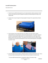
4.6.1 Seat the Patient in the Chair ................................................................................... 22
4.6.2 Placing the goggles on the patient ......................................................................... 23
4.6.3 Eye image adjustment ............................................................................................ 23
4.7 Calibration ......................................................................................................................... 24
4.8 Testing the patient ............................................................................................................ 25
4.8.1 Performing tests ...................................................................................................... 25
4.8.2 Spontaneous nystagmus ........................................................................................ 25
4.8.3 Dix-Hallpike ............................................................................................................. 25
4.8.4 Positional ................................................................................................................ 26
4.8.5 Oculomotor tests ..................................................................................................... 26

4.8.6 Caloric test .............................................................................................................. 26
4.8.7 Rotary chair tests .................................................................................................... 27
4.9 Rotary chair error messages ............................................................................................. 29
4.9.1 Rotary chair speed error ......................................................................................... 29
4.9.2 Patient safety error ................................................................................................. 29
4.9.3 Emergency stop error ............................................................................................. 29
4.9.4 Chair servo error state error ................................................................................... 29
4.9.5 Reclined chair error ................................................................................................ 30
4.10 Additional information ....................................................................................................... 30
5 CARE AND MAINTENANCE ......................................................................................................31
5.1 General maintenance procedures..................................................................................... 31
5.2 How to clean the VisualEyes™ system ............................................................................ 31
5.3 Warranty and Service ....................................................................................................... 32
5.3.1 Product Life ............................................................................................................. 32
5.3.2 Product Service ...................................................................................................... 32
5.3.3 Products returned for Repair .................................................................................. 33
5.3.4 Warranty Determination .......................................................................................... 33
5.3.5 Extended Warranty ................................................................................................. 33
5.3.6 Service Contract ..................................................................................................... 33
6 GENERAL TECHNICAL SPECIFICATIONS ..............................................................................35
6.1 Computer specifications .................................................................................................... 35
6.2 Standards .......................................................................................................................... 35
6.3 Operation and storage specifications ............................................................................... 35
6.4 Component specifications ................................................................................................. 35
6.5 Electromagnetic compatibility (EMC) ................................................................................ 37
6.5.1 Electromagnetic compatibility (EMC) for goggles with top-mounted
cameras .................................................................................................................. 37
6.5.2 Electromagnetic compatibility (EMC) for goggles with side-mounted
cameras .................................................................................................................. 39

VisualEyes™ 515/525 Instructions for Use – US Page 1
1 Introduction
1.1 About this manual
This manual is valid for the VisualEyes™ 515 and VisualEyes™ 525 Software version 2.1. These products
are manufactured by:
Interacoustics A/S
Audiometer Allé 1
5500 Middelfart
Denmark
Tel.: +45 6371 3555
Fax: +45 6371 3522
E-mail: info@interacoustics.com
Web: www.interacoustics.com
Distribution and service: Micromedical Technologies Inc.
10 Kemp Drive
Chatham, IL 62629
USA
Tel.: 1 (800) 334-4154
Web: www.micromedical.com
1.2 Intended use
The VisualEyes™ 515 and VisualEyes™ 525 system provides information to assist in the nystagmographic
evaluation, diagnosis and documentation of vestibular disorders. Nystagmus of the eye is recorded by use of
goggles mounted with cameras. These images are measured, recorded, displayed and stored in the
software. This information then can be used by a trained medical professional to assist in diagnosing
vestibular disorders. The target population for VisualEyes™ 515 and VisualEyes™ 525 system is 5 years of
age+.
The VisualEyes™ 515 and VisualEyes™ 525 system is to be used by trained personnel only, such as
audiologists, ENT surgeons, physicians, hearing healthcare professionals or personnel with a similar level of
qualifications. The device should not be used without the necessary knowledge and training to understand its
use and how results should be interpreted.
VisualEyes™ 515 and VisualEyes™ 525 will be here forth referred to as ‘VisualEyes™ system’ throughout
the instructions for use document.
1.3 Contraindications
VisualEyes™ testing may be contraindicated in patients who exhibit the following: blindness, broken nose or
other face/head trauma, recent eye surgery, lazy eye, and ptosis.
More intensive rotary chair tests may be contraindicated in patients less than 5 years of age or greater than
110 years of age.

VisualEyes™ 515/525 Instructions for Use – US Page 2
1.4 Product description
The VisualEyes™ system is a sophisticated, videonystagmography (VNG) analysis software platform that is
available in two different versions: VisualEyes™ 515 and VisualEyes™ 525. Both systems consist of a
laptop/desktop PC, goggles (top mounted/ side mounted/ front mounted cameras) and other parts as
specified in section 1.4.2.
The products vary in their testing capabilities. Tests included in VisualEyes™ 515 are Spontaneous
Nystagmus, Dix-Hallpike, Positional and Calorics. VisualEyes™ 525 includes these tests with the addition of
the oculomotor tests (Gaze, Smooth Pursuit, Saccade and Optokinetic) and the Video Frenzel test for patient
screening and rehabilitation studies. VisualEyes™ can also be used with the rotary chairs, which includes
the tests above, with the addition of Sinusoidal Harmonic Acceleration, Step Test, VOR Suppression, Visual
VOR and Video Frenzel.
Tests
VisualEyes™
515
VisualEyes™
515 with
reclining chair
VisualEyes™
525
VisualEyes™
525
with reclining
chair
Calibration
Yes
Yes
Yes
Yes
Spontaneous
nystagmus
Yes
Yes
Yes
Yes
Gaze
No
No
Yes
Yes
Smooth Pursuit
No
No
Yes
Yes
Random Saccade
No
No
Yes
Yes
Optokinetic
No
No
Yes
Yes
Dix Hallpike
Yes
Yes
Yes
Yes
Positional
Yes
Yes
Yes
Yes
Bithermal Caloric
Yes
Yes
Yes
Yes
Sinusoidal
Harmonic
Acceleration
No
Yes
No
Yes
Step Test
No
Yes
No
Yes
VOR Suppression
No
Yes
No
Yes
Visual VOR
No
Yes
No
Yes
Video Frenzel
No
No
Yes
Yes
1.4.1 Minimum requirements to PC
Laptop PC: One 34mm PCExpressCard slot available (FireWire® systems only).
Desktop PC: One PCI Express card available (FireWire® systems only).
USB port required (expanded by USB hub)
Intel i5 processor 2.5 GHz or better, and not older than 2nd generation
Minimum 8 GB RAM or more.
Hard drive with min. 250GB space.
Minimum display of 1366X768 (Higher resolution recommended).
Touch monitor or laptop with touch screen is highly recommended though not required.
Operating Systems supported:
Windows® 7 32-bit and 64-bit.
Windows® 8.1 64-bit.
Windows® 10 64-bit.

VisualEyes™ 515/525 Instructions for Use – US Page 3
1.4.2 Included and optional parts
The VisualEyes™ system is delivered with the following items based on system configuration.
USB camera systems
FireWire® camera systems
Included parts
Hand held RF remote control and/or foot pedal
VisualEyes™ 515/525 installation media
OtoAccess™ Database media
Cleaning cloth for lens and goggle mirrors
Optional parts
based on goggle
type
2D-VOGfw goggle w. side
mounted cameras
USB 2.0 camera module (two
modules in binocular configuration)
Disposable goggle foam pads – box
of 24 pcs
1.5 mm hexagon screwdriver for
camera retaining screws
7-port USB 3.0 hub w. external power
supply
USBM2.1A goggle w. front
mounted camera
Adult mask for USB monocular
camera
Camera module with 15’ USB cable
7-port USB 3.0 hub w. external power
supply
USBM2.1P goggle w. front
mounted camera
Pediatric mask for USB monocular
camera
Camera module with 15’ USB cable A
to Mini B
7-port USB 3.0 hub w. external power
supply
BG4.0KUSB goggle w. top
mounted cameras
Goggles USB Asian faceplate
binocular
Two 15’ USB cables A to Mini B
7-port USB 3.0 hub w. external power
supply
BG4.0USB goggle w. top mounted
cameras
Goggles USB binocular
Two 15’ USB cables A to Mini B
7-port USB 3.0 hub w. external power
supply
2D-VOGfw goggle w. side mounted
cameras
FireWire® camera module (two modules
in binocular configuration)
Disposable goggle foam pads – box of
24 pcs
PCExpressCard stabilization kit (laptop
configuration)
PCExpressCard (for laptop
configuration)
PCI ExpressCard (for tower PC
configuration)
4-port USB hub

VisualEyes™ 515/525 Instructions for Use – US Page 4
Optional parts
based on
reclining chair
type
Using the Orion rotary chair
Orion rotary chair
USB cable
Emergency stop button with Ethernet
connector
Power cord
Using the System 2000 reclining
chair
System 2000 reclining chair
Chair controller
USB cable
Emergency stop button
Power cord
Using the Nydiag 200 rotary chair
Nydiag 200 rotary chair
Ethernet to USB chair cable
Emergency stop button with Ethernet
connector
FireWire® cable
Table 1. VisualEyes™ included and optional parts.

VisualEyes™ 515/525 Instructions for Use – US Page 5
1.5 Warnings and precautions
Federal law restricts the sale, distribution, or use of this system to, by, or on the order of a licensed medical
practitioner. The system components should not be modified without consulting the manufacturer.
General warnings and precautions
WARNING indicates a hazardous situation which, if not avoided, could result
in death or serious injury.
CAUTION, used with the safety alert symbol, indicates a hazardous situation
which, if not avoided, could result in damage to the equipment.
NOTICE NOTICE is used to address practices not related to personal injury or
damage to the equipment.
1. This equipment is intended to be connected to other equipment thus forming a Medical Electrical
System. External equipment intended for connection to signal input, signal output or other
connectors shall comply with the relevant product standard e.g. IEC 60950-1 for IT equipment and
the IEC 60601-series for medical electrical equipment. In addition, all such combinations – Medical
Electrical Systems – shall comply with the safety requirements stated the general standard IEC
60601-1, edition 3, clause 16. Any equipment not complying with the leakage current requirements in
IEC 60601-1 shall be kept outside the patient environment i.e. at least 1.5 m from the patient support
or shall be supplied via a separation transformer to reduce the leakage currents. Any person who
connects external equipment to signal input, signal output or other connectors has formed a Medical
Electrical System and is therefore responsible for the system to comply with the requirements. If in
doubt, contact qualified medical technician or your local representative.
2. A Separation Device (isolation device) is needed to isolate the equipment located outside the patient
environment from the equipment located inside the patient environment. In particular such a
Separation Device is required when a network connection is made. The requirement for the
Separation Device is defined in IEC 60601-1, edition 3, clause 16.
3. The system must not be used in presence of explosive or flammable gases.
4. The goggles should not be worn by patients with strong defective vision and abnormal rare blink.
Please consult a specialist in such circumstances before using the mask on these types of patients.
5. The system must be switched off before cleaning. Patients should not be in the rotary chair or
wearing the goggles while chair is being serviced.
6. Do not use any additional multiple socket-outlet or extension cord.
7. No modification of this equipment is allowed without manufacturer authorization.
8. The manufacturer will make available on request circuit diagrams, component part lists, descriptions,
calibration instructions, or other information that will assist service personnel to repair those parts of
this system that are designated by the manufacturer as repairable by authorized service personnel.
9. For maximum electrical safety, turn off the power from a mains powered instrument when it is left
unused.
10. The instrument is not protected against harmful ingress of water or other liquids. If any spillage
occurs check the instrument carefully before use or contact the manufacturer for service.
11. Do not use the equipment if it is showing visible damage.

VisualEyes™ 515/525 Instructions for Use – US Page 6
1. Use this device only as described in this manual.
2. The system must be serviced at least once a year. The service must include a safety test.
3. Do not use the equipment if the equipment is damaged; have the equipment serviced.
4. Only personnel with proper training (skilled personnel) should operate the system.
5. Proper use of this device depends on careful reading of this manual and all additional instructions
and labels.
6. Allow the system to obtain room temperature before using the equipment. Any components that
have been stored previously should be brought to room temperature before usage.
7. Patients cannot use corrective eyeglasses when tested though corrective contact lenses can be
worn to improve visual acuity.
8. Patients should not wear makeup around the eyes. Cosmetic tattoos or permanent makeup may
interfere with eye tracking and should be disclosed to the testing facility prior to patient testing.
9. Disposable foam pads used with the side mount camera goggles are single use and should be
replaced after testing the patient. Front mount camera goggles and top mount camera goggles
should be disinfected with approved cleansing wipes as described in the care and maintenance
section of this manual.
10. Be sure to use only stimulation movements that are acceptable to the patient.
11. If the system uses a rotary chair, inform the patient that the test battery will include rotary tests.
Patients with a history of motion sickness should be informed and monitored during testing. If the
patient is feeling discomfort, the tester should stop the test within the software. If the test needs to
be stopped immediately, the Emergency Stop button should be pressed to stop the chair. The
Nydiag 200 rotary chair also has a patient controlled stop button underneath the right armrest for the
patient to use if the patient cannot tolerate the test.
12. If the system uses a rotary chair, the chair is not allowed to spin when it is reclined. The software
will alert the operator that the chair is reclined and will not allow the rotary chair test to be performed.
13. Goggles headband straps should be checked with each patient. If the headband strap does not
remain fastened, then the headband strap should be replaced. Replacement headband straps are
available from the manufacturer.
14. If the system uses a rotary chair, the chair center should be situated at least 1 meter (39 inches)
from the center axis to any adjacent object to accommodate the chair in a reclined state.
NOTICE
1. To prevent system faults take appropriate precautions to avoid PC viruses and similar.
2. Clean the camera lens and the infrared coated mirrors of the goggles regularly to avoid shadows on
the displayed images.
3. Do not drop the components and avoid other undue impacts to this device. If the system is
damaged, contact the manufacturer for repair. Do not use the system if any damage is suspected.
4. Although the instrument fulfils the relevant EMC requirements precautions should be taken to avoid
unnecessary exposure to electromagnetic fields, e.g. from mobile phones etc. If the device is used
adjacent to other equipment it must be observed that no mutual disturbance appears.
Within the European Union it is illegal to dispose electric and electronic waste as
unsorted municipal waste. Electric and electronic waste may contain hazardous
substances and therefore has to be collected separately. Such products will be
marked with the crossed-out wheeled bin. The cooperation of the user is important in
order to ensure a high level of reuse and recycling of electric and electronic waste.
Failing to recycle such waste products in an appropriate way may endanger the environment and
consequently the health of human beings.

VisualEyes™ 515/525 Instructions for Use – US Page 7
2 Unpacking and inspection
2.1 Unpacking and inspection
Check shipping containers and contents for damage
When the system is received, please check the shipping box for rough handling and damage. If the box is
damaged it should be kept until the contents of the shipment have been checked mechanically and
electrically.
If the instrument is faulty, please contact your local distributor. Keep the shipping material for the carrier’s
inspection and insurance claim.
Keep shipping containers for future shipment
Keep the shipping box and/or shipping crates if the instrument has to be returned for service. Contact your
local distributor for on-site service.
2.2 Reporting imperfections
Inspect before connection
Prior to connecting the product it should once more be inspected for damage. All of the cabinet and the
accessories should be checked visually for scratches and missing parts.
Report immediately any faults
Any missing part or malfunction should be reported immediately to the supplier of the instrument together with
the invoice, serial number, and a detailed report of the problem.
Products returned for repair
If the manufacturer requests that you return the product for evaluation or repair, pack the product well,
preferably in the original shipping container with a Return Material Authorization (RMA) number provided by
the manufacturer. Systems with optional rotary chairs will be serviced on-site by the local distributor.

VisualEyes™ 515/525 Instructions for Use – US Page 8
2.3 Marking
The following marking can be found on the instrument:
Symbol
Explanation
Type BF applied parts.
Type B applied parts.
Read and understand instructions for use before operating this device.
WEEE (EU-directive).
This symbol indicates that when the end-user wishes to discard this product,
it must be sent to separate collection facilities for recovery and recycling.
Failing to do so may endanger the environment.
0123
The CE-mark indicates that the manufacturer meets the requirements of
Annex II of the Medical Device Directive 93/42/EEC for the quality system.
Manufacturer.
Year of Manufacturer.
Do not re-use.
Parts like foam cushions and similar are for single use only.
Reference number used to denote the model of the equipment.
Table 2.3.1 Symbol legend.

VisualEyes™ 515/525 Instructions for Use – US Page 9
3 Setup and installation
3.1 Introduction to VisualEyes™ software
The VisualEyes™ software combines leading edge technology with touch screen capability in a new
streamline software interface. VisualEyes™ software is considered the standard for testing the vestibular
system and oculomotor functions, a process known as vestibular assessment. It involves the use
of infrared goggles to record and analyze eye movements during visual stimulation, positional changes and
caloric stimulation. The VisualEyes™ software can be configured with a rotary chair to test patients’
vestibular ocular reflex (VOR).
3.2 Installation of OtoAccess™ database
The VisualEyes™ software is accessed through the Interacoustics OtoAccess™ database. The
Interacoustics OtoAccess™ database is used for storage of patient information and data recordings.
Your computer/ laptop will have OtoAccess™ and VisualEyes™ software pre-installed.
If you find that it is not already installed, or if a re-install is required please read the instructions for use
included with the OtoAccess™ installation media (CD or Flash drive) or contact your distributor.
3.3 Installation of VisualEyes™ software
NOTICE
The OtoAccess™ database must be installed prior to installing VisualEyes™ software.
The VisualEyes™ software will be pre-installed on the computer purchased from Interacoustics. In the event
that software must be re-installed, please follow these instructions.
1. Insert the VisualEyes™ Installation CD or flash drive into the computer.
2. If the installation procedure does not start automatically, click Start, then go to My Computer and
double click the DVD/CD-RW drive or Flash Drive to view the contents of the installation media.
3. Double click the Micromedical VisualEyes™ Installer file to initiate the installation.
4. The VisualEyes™ Setup Wizard will start.
5. Check the box to accept the terms and click Install.
6. After the installation completes, exit the installer.
7. Remove the installation media from the drive and store in a convenient place.
The VisualEyes™ installation will configure OtoAccess™ for VisualEyes™ testing. To use the VisualEyes™
software, select the Micromedical VisualEyes™ instrument from OtoAccess™.
3.4 Installation of rotary chair drivers
3.4.1 Installing drivers for Nydiag 200 rotary chair
Open Windows® Explorer. Navigate to the following location:
C:\Program Files (x86)\Interacoustics\Micromedical VisualEyes™\Driverfiles
Run the program kvaser_drivers_setup.exe.
When asked which components should be installed, choose the default selections for installing the Drivers
(32/64-bit x86), Start Menu Shortcuts, and GUI tools.
When asked for the destination folder for installing the drivers, choose the default location of C:\Program
Files\Kvaser\Drivers.
During installation Windows Security may request permission to install the device software from Kvaser AB.
Check the box to always trust software from “Kvaser AB”, then choose Install.
Connect the CAN motor control cable from the blue reclining chair to the computer’s USB port.

VisualEyes™ 515/525 Instructions for Use – US Page 10
3.4.2 Installing drivers for System 2000 reclining chair
Open Windows® Explorer. Navigate to the following location:
C:\Program Files (x86)\Interacoustics\Micromedical VisualEyes™\Driverfiles
Run the program icalsetup.exe.
Click on Setup to begin installing InstaCal.
Choose to install InstaCal to the default location of C:\Program Files (x86)\Measurement Computing\DAQ\.
When asked which program features should be installed, choose the default option to install the Universal
Library Examples.
During installation Windows Security may request permission to install the device software from
Measurement Computing. Check the box to always trust software from “Measurement Computing”, then
choose Install. The computer will need to be rebooted after the InstaCal setup is complete.
Verify the chair controller is connected to the rotary chair and PC and the FireWire cable from the chair is
connected to the PC. Windows will recognize the chair with the new drivers.
After the drivers have been installed, launch the InstaCal software.
In Windows® 7 / 8.1, click on Start > All Programs > Measurement Computing > InstaCal.
In Windows® 10, click on Start > All apps > Measurement Computing > InstaCal.
When the InstaCal software is launched, the software will detect the rotary chair as a PCI-DAS6025 device.
Click on the OK button to register the device in the program.
Figure 3.4.1 Detecting the System 2000 reclining chair in InstaCal
Right-click on the device in InstaCal after it is registered and choose Configure. Alternatively the Configure
button is also the fourth icon from the left. In the combo box choose 16 Referenced (to GND) Single Ended
for the No. of Channels field and choose OK. Exit InstaCal.
Figure 3.4.2 Configure the System 2000 reclining chair in InstaCal

VisualEyes™ 515/525 Instructions for Use – US Page 11
3.4.3 Installing drivers for the Orion rotary chair
Open Windows® Explorer. Navigate to the following location:
C:\Program Files (x86)\Interacoustics\Micromedical VisualEyes™\Driverfiles
Run the program icalsetup.exe.
Click on Setup to begin installing InstaCal.
Choose to install InstaCal to the default location of C:\Program Files (x86)\Measurement Computing\DAQ\.
When asked which program features should be installed, choose the default option to install the Universal
Library Examples.
During installation Windows Security may request permission to install the device software from
Measurement Computing. Check the box to always trust software from “Measurement Computing”, then
choose Install. The computer will need to be rebooted after the InstaCal setup is complete.
At this point connect the USB cable from the rotary chair to the computer. Windows will recognize the chair
with the new drivers.
After the drivers have been installed, launch the InstaCal software.
In Windows® 7 / 8.1, click on Start > All Programs > Measurement Computing > InstaCal.
In Windows® 10, click on Start > All apps > Measurement Computing > InstaCal.
When the InstaCal software is launched, the software will detect the rotary chair as a USB-231 device. Click
on the OK button to register the device in the program.
Figure 3.4.3 Detecting the Orion rotary chair in InstaCal
Right-click on the device in InstaCal after it is registered and choose Configure. Alternatively the Configure
button is also the fourth icon from the left. In the combo box choose 16 Referenced (to GND) Single Ended
for the No. of Channels field and choose OK. Exit InstaCal.

VisualEyes™ 515/525 Instructions for Use – US Page 12
Figure 3.4.4 Configure the Orion rotary chair in InstaCal

VisualEyes™ 515/525 Instructions for Use – US Page 13
3.5 Uninstall software
In Windows® 7 and 8.1, the VisualEyes™ software can be removed from Programs and Features.
1. Open Windows® Control Panel and then select Programs and Features. If the Category option is
used, then under Programs choose Uninstall a program.
2. Select the Micromedical VisualEyes™ entry. Click on Uninstall.
3. In the installer package, choose Uninstall. Once the program is uninstalled, close the installer and
Control Panel.
In Windows® 10, the VisualEyes™ software can be removed from Settings.
1. From the start menu choose Settings
2. Choose Apps. Choose System, then select Apps & features.
3. In the sort box, choose Sort by name.
4. Select the Micromedical VisualEyes™ program in the list, then click on Uninstall.
5. Confirm the process by clicking on the Uninstall button.
6. In the installer package, choose Uninstall. Once the program is uninstalled, close the installer and
Settings.
3.6 Hardware setup
The VisualEyes™ system is composed of several selected pieces of equipment. The software is designed to
be compatible with both Interacoustics a/s and Micromedical Technologies Inc. equipment.
Each piece of equipment, its function and installation is described below.
3.6.1 Laptop/desktop PC
The VisualEyes™ software comes preloaded on a dedicated laptop or desktop PC (Figure 3.6.1). If the
VisualEyes™ software will be installed on additional computers please follow the recommended minimum
PC requirements.
Figure 3.6.1 Laptop / desktop PC
3.6.2 Television/projector display
Figure 3.6.2 TV and projector display
VisualEyes™ system is to be configured with either a Projector or a TV (Figure 3.6.2).The TV may be
mounted on the wall or placed on a table with the TV feet. Windows Desktop is extended across both
displays.

VisualEyes™ 515/525 Instructions for Use – US Page 14
3.6.3 Side mount camera goggles
The VisualEyes™ goggles allow for recording of eye movements during various test conditions, both with
and without visual stimulation. The VisualEyes™ side mount goggles hold FireWire® or USB cameras that
are used to record the eye images. The cameras use infrared light (IR), which is not visible to the naked eye.
The IR illumination enables sessions to be performed in complete darkness.
The FireWire® or USB cameras are fixed on the sides of the goggles (Figure 3.6.3).
Figure 3.6.3 Side mount camera goggles
The goggles come with replaceable foam cushions (Figure 3.6.4) that are removed between patients by
pulling the used foam cushion off of the hook and loop pads on the inside of the mask and then aligning a
new foam cushion on top of the Velcro.
Figure 3.6.4 Replaceable foam cushions for side mount camera goggles
The front cover plate of the side mount goggle is magnetically fixed and can easily be removed for visual
stimulation tests (i.e. oculomotor). The mask has an adjustable Velcro head strap that comfortably secures
the goggles to the patient. Side mount camera goggles can be configured with one camera and cover for
monocular systems. In this configuration, the user would physically move the camera to the side of the
goggles to record the desired eye, and the cover would be placed on the other side to block out light in vision
denied tests.

VisualEyes™ 515/525 Instructions for Use – US Page 15
3.6.4 Top mount camera goggles
The binocular video goggles (Figure 3.6.5) block out ambient light with the easy-to-place cover over the
portal for vision-denied testing. Side-lights on the goggles are programmed to flash to remind the operator
which ear to irrigate during the caloric test and are also used to provide illumination when placing the cover
on the goggles. On the left side of the goggles is a switch to start and stop tests. The binocular video
goggles have an adjustable Velcro head-strap that secures the goggles while still providing patient comfort.
Figure 3.6.5 Top mount camera goggles. Cover slips over front of goggles for vision-denied testing. The
switch on the left side of the goggles starts and stops the test
3.6.5 Front mount camera goggles
The front mount camera goggles use a single USB camera pressed into the camera portal on the front of the
goggles mask. The camera can be placed into either camera portal to record the desired eye. The cable is
secured in the cable clip above the portal. Each portal has a swivel cover plate to provide vision-denied
testing. The goggles have an adjustable head-strap that secures the goggles while still providing patient
comfort. The front mount camera goggles are typically used for smaller and younger patients.
Figure 3.6.6 Front mount camera goggles. Left picture shows the standard goggles, and the right picture
shows the small face goggles

VisualEyes™ 515/525 Instructions for Use – US Page 16
3.6.6 Rotary chair (optional)
The reclining rotary chair provides sinusoidal harmonic acceleration (SHA) test and step test capability to the
VisualEyes™ system. The reclining rotary chair can also be used as the exam table for positional and
caloric testing. The backrest can be reclined to 30 degrees from horizontal for caloric irrigations. Positional
tests can be performed with the backrest reclined to 0 degrees horizontal. For Dix-Hallpike tests, the
headrest can be removed on the System 2000 and Orion chairs to allow the clinician to bring the head below
the frame. A head strap located on the back of the System 2000 and Orion chairs’ headrest secure the
patient’s head to the head rest during rotation tests.
Figure 3.6.7 Reclining rotary chair.
3.6.7 The foot pedal (optional)
The foot pedal (Figure 3.6.8) allows you to begin the measurement testing by pressing the foot switch so
you have both hands free to look after the patient (e.g. Dix-Hallpike) or to operate other devices (e.g., caloric
irrigators). Connection with the PC is via a USB port.
Figure 3.6.8 VisualEyes™ foot pedal
/