Page is loading ...

VERSION
DESCRIPTION
DATA
1.0
First release
February 2016

NOTES :……………………………………………………………………………………………


Contents
Quick Introduction .............................................................................................................................................. 1
GAMP-2000 and App Esa Regatta ..................................................................................................................... 2
Information for the user ..................................................................................................................................... 3
Symbology .......................................................................................................................................................... 3
Precautions antistatic propeties ................................................................................................................ 4
Input supply connection and other equipment .......................................................................................... 4
Installation ................................................................................................................................................. 5
Ventilation ................................................................................................................................................. 5
Maintenance ............................................................................................................................................. 5
Cleaning .................................................................................................................................................... 5
Warranty .............................................................................................................................................................. 6
CE Certificate ...................................................................................................................................................... 6
RAEE .................................................................................................................................................................... 6
RoHS .................................................................................................................................................................... 6
Rules used in this manual ................................................................................................................................. 6
The “Mode” of Windows registry: .............................................................................................................. 6
Hexsadecimalnumbering: ......................................................................................................................... 6
Symbols and text used the pinout tables: ................................................................................................. 6
Tecnical Support ................................................................................................................................................. 7
Carriage .................................................................................................................................................... 7
PART 1 - INTRODUCTION .................................................................................................................................. 8
General description ............................................................................................................................................ 9
Connectors Interfaces ...................................................................................................................................... 10
Meaning of LEDs .................................................................................................................................... 11
Front interfaces ................................................................................................................................................. 11
Power specifications ........................................................................................................................................ 12
Mechanical properties ...................................................................................................................................... 13
Protection level (IP Rating) .............................................................................................................................. 13
PART 2 – FUNCTIONALITY AND SYSTEM CONFIGURATION...................................................................... 14
Step 1: Configuring GAMP-2000 ..................................................................................................................... 15
Step 1.1: Turn on the Sysyem .................................................................................................................... 15
Meaning of LEDs .................................................................................................................................... 15
Step 1.2: Connect Magneto System to the Host PC ................................................................................ 15
1.2.2 Select WiFi channel ................................................................................................................................. 17
1.2.2.1 Firmware Update................................................................................................................................... 17
1.2.2.2 Software Versions ................................................................................................................................ 18
1.2.3 Baud Rate ............................................................................................................................................... 19
1.2.5 Filtering sentences ................................................................................................................................ 20
1.2.16 Internal GPS Setting & ESA Setting................................................................................................... 29
Step 2: Third-party Software Link .................................................................................................................. 32
Step 3: Hardware connections ................................................................................................................... 33
Step 4: SD Data Logger Managment (ADR) .................................................................................................. 34
5 NMEA 2000 - 0183 Conversion Tabe .......................................................................................................... 38

1
Quick Introduction
With GAMP-2000 you can connect various NMEA 0183 and NMEA 2000 based system. Boat
instruments, GPS, AIS, PC, Autopilot are connected together and the data are sent even
through the NMEA 0183 ports, NMEA 2000 port or the Wi-Fi connection.
It is possible to connect via Wi-Fi up to 4 devices capable to receive and transmit NMEA 0183
data, such as iPhone, iPad, iPod touch and Android devices.
The GAMP-2000 have an NMEA 2000 port capable of communicating on an NMEA 2000
network. NMEA 2000 messages (called PGN’s) are translated into NMEA 0183 sentences. The
GAMP 2000 also translate NMEA 0183 sentences into NMEA 2000 PGN’s.
Unique worldwide, it allows saving navigation data by command; the management is made by
an app (iOs, in the future Android as well) which activates the recording, stops it and allows
transmitting the registrations on your portable device via Wi-Fi .
Available version which allows the use of “esa regatta” and “esa training” apps.
Esa GAMP-2000 multiplexer has three or four, depending on the version, opto-isolated inputs to
connect data sending davices, called Talkers, two outputs, to connect multiple reciving devices, called
Listeners and one NMEA 2000 interface to connect to an NMEA 2000 backbone.
Esa GAMP-2000 syncronise the NMEA sentences from different talkers and send them to the outputs.
Esa GAMP-2000 also translate NMEA 2000 messages (PGN’s) into NMEA 0183 sentences and vice
versa.
The way the sentensece are combined, is completely manageable by the user through the ‘Esa
configuration manager’ software supplied with the GAMP.
The particularity of Esa GAMP-2000, compared the standard multiplexers on the market, is that it is
not limited to output NMEA 0183 strings and NMEA 2000 PGN’s, which compared the information they
carry, have a considerable amount of data to send, but also transmit data for the navigation software
Esa Regatta, with a proprietary protocol much lighter to send thereby reducing delays introduced by
the multiplexer itself.
Is still maintained the possibility to send output Wi-Fi both NMEA 0183 and Esa sentences, for a
combined use of Esa Regatta and third-party applications.
Another unique feature of the GAMP-2000 is that inside housed a MicroSD card connector (optional
memory card not included) to be used as a data logger, a tool, that is able to record in its internal
memory all navigation data every second, to use them for subsequent analysis.
To manage the operations of reading / writing / storing these files was created an app, a free
download from the Apple Store, which is described in this manual in Section 4.

2
GAMP-2000 and App Esa Regatta
The “GAMP-2000-esa” comes already configured for use with App Esa Regatta, downloadable from the
Apple Store.
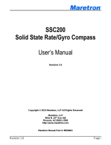
We recommend you to connect the output of your network NMEA instruments to In1 input of GAMP and
connect to an NMEA 2000 network with the NMEA 2000 connector, as shown in the following figure.
Note: if the GAMP-2000 is connected to an NMEA 2000 network no additional external power supply is
needed, otervise and adittional external powers suplay of 12V-24V is needed.
Once on the system Esa-GAMP-2000, scan WiFi networks with your Apple device in which you
installed Esa Regatta, then:
1. Connect to the network ESA_GAMP_2k and enter, when prompted, the password FAE95A0697
2. Enter the IP address: 192.168.1.3.
3. Launch Esa Regatta.
And advisable to change the network name and password to have no trouble connecting with other
systems GAMP-2000 that they are nearby. (see section 1.2.1 Customizing network name and
password).
A/+
B/-
NMEA Out
Instruments
NMEA 0183
Instruments
NMEA 2000
NMEA 2000 backbone

3
Information for the user
Read carefully and understand the instructions in this manual before any use of the device.
Whenever doubts arise regarding the operation of the product, consult this manual or contact the
technical support (inf[email protected])
Keep this manual for future reference.
In order to reduce the risk of personal injury, electrical shock, fire or damage to the equipment,
users must observe the following precautions, as well as exercising careful judgment,
whenever it is necessary to install or use the product described in this manual.
Although every attempt has been made to ensure the accuracy of this manual, AstraYacht s.r.l
declines any liability arising from any errors or omissions, or use of the information contained in this
manual.
AstraYacht reserves the right to modify or correct the content this manual at any time, without notice.
Symbology
To facilitate the understanding of the contents of this manual have been used these symbols:
SYMBOL
MEANING
DANGER!
This symbol indicates the risk of electric shock and severe injury or death if safety instructions are not
followed.
Use precautions for their own safety and others, making sure that you meet the requirements for the
environment where the product is used.
ATTENTION!
This symbol indicates the user:
The presence of a hazard that may result in death or serious injury if the safety instructions are not
observed
That a misuse of the equipment or failure to follow instructions could damage things or the same
equipment
Use precautions for their own safety and others, making sure that you meet the requirements for the
environment where the product is used.
NOTE:
This symbol indicates a suggestion or a tip that helps you make better use of the equipment.

4
Care and warnings for safe operation
The user must observe the precautions and warnings in this manual during all phases of installation,
service and repair of the product. Failure to follow these precautions and warnings violate the safety
standards of design, manufacture and planned usage of the product.
AstraYacht srl declines any responsibility for failure by the user of the precautions and warnings given
in this manual.
The safety precautions listed below represent some warnings AstraYacht srl knows. The user shall
observe these warnings and every other precaution is necessary to the proper functioning of the
product, even if not expressly stated in this manual.
Prohibition on the use in explosive environments
ATTENTION!
You may not use the equipment:
Inplaces with the presence of toxic substances, gases or flammable liquids and/or explosives
in pros itself of heat sources and naked flames
Precautions antistatic propeties
ATTENTION!
In order to prevent irreversible damage due to ESD (electrostatic discharge), it's a good idea to take
all the necessary precautions (e.g. use a grounded wrist strap) before handling the equipment.
Input supply connection and other equipment
DANGER!
Failure to observe the following precautions may result in damage, fire or electric shock, with
possible serious injuries.
To avoid personal injury, always disconnect the power and discharge equipment circuits
before touching the latter
Use a power supply whose voltage and frequency correspond to those indicated on the
label of the appliance. In case of doubt contact support AstraYacht Technician (see third
and fourth of the cover of this manual for more details) or Manager for electricity
Before making connections to other equipment to read the instructions for use of the same
equipment
Always unplug the power to the equipment before making connections or disconnections
Do not attach/detach operations with damp or wet hands
Before using the appliance check that the power cables and connection are not damaged,
knotted or crushed
Do not route the power cables and connection through areas where they can be crushed or
damaged
Supplying power to the equipment only after having performed and checked all connections,
avoiding overruns
Do not tamper with the power connections.

5
Installation
ATTENTION!
Do not place the unit on unstable or sloping surface upon which it may fall causing serious
injury to people.
Do not bring the equipment to heat sources and naked flames.
NOTE:
If the appliance must be moved from one place to another with different ambient temperature, before
connecting it to the power, wait a few minutes to allow the unit to reach the new ambient temperature.
Ventilation
ATTENTION!
To avoid overheating, we must ensure proper ventilation equipment.
Follow the instructions below:
If you install the appliance in a cupboard, rack or other enclosed space, be sure to leave
sufficient space around the appliance to allow adequate air circulation and a more simple link
management
Do not cover any ventilation openings of the equipment.
Maintenance
DANGER!
NEVER OPEN THE WORKING DEVICE!
DO NOT ATTEMPT TO REPAIR OR DISASSEMBLE THIS EQUIPMENT!
For any maintenance and/or repair of the equipment require the intervention of qualified personnel
authorized by AstraYacht.
If the equipment is not working properly, particularly if unusual odor emanates, unplug it immediately
and contact support AstraYacht Technician (see third and fourth of the cover of this manual for more
details).
Cleaning
ATTENTION!
Disconnect the equipment from the power supply before cleaning.
To remove dust and fingerprints from the outer surfaces of the product:
Use a soft, dry cloth
DO NOT use cleaning agents, solvents, powders or abrasive sponges

6
Warranty
Contact the nearest Sales Office AstraYacht (see the third and fourth of the cover of this manual for
more details) for the warranty terms.
CE Certificate
This product carries a CE mark.
The CE mark on this product indicates that the system has been tested and complies with EMC
Directive 2004/108/EC and the low voltage Directive 2006/95/EC.
AstraYacht is not responsible for the use of its products together with equipment (e.g.: power supplies,
personal computers, etc.) that are not marked EC and complying with the technical requirements set
out in this manual
RAEE
The information below is provided in compliance with the laws in force on waste disposal electrical
and electronic equipment (RAEE).
The symbol at the side shows the equipment/packaging/instructions/warranty
sheetindicates that the product (including all components, subassemblies and
consumables which are part of the product), is regarded as ' waste electrical and
electronic equipment WEEE or '. Atthe end of his life the useful must be collected and
disposed of separately from other waste.
Because of substances in electrical and electronic equipment, improper use or incorrect disposal
can cause damage to human health and the environment.
For WEEE has the obligation not to dispose of as municipal waste and such waste, to
aseparate collection.
Please inform yourself about the local separate collection system for WEEE
In case of abusive disposal of such wastes are sanctions for transgressors.
RoHS
This equipment, including all components, subassemblies and consumables which are part of the
product, in compliance with current legislation, conforms to normativaeuropea 2002/95/EC (also
known as RoHS, Restriction on the use of certain Hazardous Substances) on the restriction of use of
certain hazardous substances in electrical and electronic equipment (EEE).
Rules used in this manual
In the manual the following conventions are used:
The “Mode” of Windows registry:
SIMBOL/ TEXT
DEFINITION
RW
Readable and Writable register
RO
Read only register
W
Meaning of the register when written
R
Meaning of the register when read
Hexsadecimalnumbering:
Hexadecimal numbers are marked with an "h” suffix (for example: 11Ch)
Symbols and text used the pinout tables:
SIMBOL/ TEXT
DEFINITION
◄
Input

7
►
Output
◄►
Bidirectional
▬
Passive
Module specific
Dependent on installed module
NC
Not connected
Reserved
Private use forAstraYacht, must remain not connected
#
Active low signal
Tecnical Support
Contact support AstraYacht Technician (see third and fourth of the cover of this manual for more
details) for any doubt/question to technical questions related to the functioning of the equipment, or to
receive information regarding repairs or prodcedure for the return of the equipment.
Carriage
The transport of the equipment, whatever the reason, must be carried out after having properly
packed with antistatic material, and have it placed in a sturdy carton with sufficient packing material
against shocks and vibrations.
ATTENTION!
The warranty on a product returned to AstraYacht will lapse automatically if the product arrives
damaged due to improper packaging!

8
PART 1 - INTRODUCTION

9
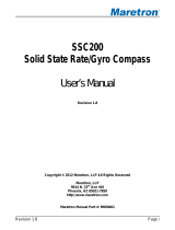
General description
The GAMP-2000 multiplexer has as its objective to be an on board computer light that can be used for
wired and wireless communications. The system consists of a motherboard with WiFi, USB, serial
ports, Controller Area Network (CAN Bus), and to 80 MHz PIC32 microcontroller. The system, based
on the configuration can fit a variety of applications. This manual will be dealt with in particular the
application of NMEA 0183 Multiplexing and NMEA 2000 to NMEA 0183 translation for nautical
application.
Figure 1. GAMP-2000-esa
Order code
Functionality
Version description
GAMP-2000-esa
1. WiFi output (both NMEA
0183 & ESA sentences)
2. 3 or 4 NMEA 0183 Input
3. 1 NMEA 0183 output
4. 1 RS232 output and
maintenance
5. 1 NMEA 2000 port
Built-in:
NMEA 0183 multiplexing
capability
translating NMEA 2000 to
NMEA 0183 and vice vers
NMEA 0183 Wi-Fi
functionality
Esa Wi-Fi functionality
GAMP-2000
1. WiFi output (only NMEA
0183 sentences)
2. 3 or 4 NMEA 0183 Input
3. 1 NMEA 0183 output
4. 1 RS232 output and
maintenance
5. 1 NMEA 2000 port
Built-in :
NMEA 0183 multiplexing
capability
translating NMEA 2000 to
NMEA 0183 and vice vers
NMEA 0183 Wi-Fi
functionality
Hardware caratteristics are as follows:
Processor PIC32 32bit 80Mhz (PIC32MX795F512H), 512KB flash + 12KB per il boot, 128 KB RAM
3 or 4 RS422 (Input NMEA 0183) and 1RS232/422/485 auto switchable (1 Output NMEA 0183), serial
optoisolated
1 Controller Area Network (CAN Bus) port

10
WiFi module MRF24WG0MBwith Access Point (4 devices supported) and Client with UFL connector for
external antenna
MicroSD connector for storage (SD memory card Optional)
Reset switch
Power supply9 –36Vdc (rated voltage 12-24VDC)
1 Power On LED, 1 Status WiFi LED, 1 Overflow LED
Connectors Interfaces
In order to connect the GAMP-2000 to an NMEA 0183 network, the system has two cable clamp to
interface directly to the screw connectors on the board for which can be accessed by opening the
cover. To connect to an NMEA 2000 network one standard NMEA 2000 conector is present.
Power input 9-36 VDC(J7)
NMEA 1 Input (J2) [default baud rate 4800]
NMEA 2 Input(J3) Compatible with RS232* [default baud rate 4800]
NMEA 3 Input(J4) Compatible with RS232* [default baud rate 38400]
NMEA 4 Input (J5) only version 2.1
NMEA 1 Output (J6) [default baud rate 4800]
RS232 Output e maintenance
o This port shares the same data stream of NMEA Output port.
Optional (not installed)
Ethernet (J11)
The connectors are marked with special signs on the Board.
* The standard NMEA0183 expected that the input signals are differential type RS422 ([In +, In -] or [In A, In B]
according to the notations). If the device (talker) that we are going to connect has an output in RS232 format
(ie [Tx, GND]), use the inputs 2 and 3 of GAMP-0183 suitably modified to be compatible with this standard,
connecting theTx output to the In + and the GND terminal to the In -.

11
Meaning of LEDs
LED COLOR
MEANING
LED STATUS
Green
On/Off
On:System On
Off: System Off
Blue
System state
Blinking: WiFi connected
On: WiFi active
Off: WiFi Off
Red
System state
On:overflow ofone of the NMEA Input signals
Off: no overflow
Front interfaces
Two connectors, M1 and M2, are available on the front panel of the magneto system and one NMEA
2000 connector is present on the rear panel of the magneto system.
NMEA
Inputs 1-4
NMEA
Out
POWER
RS232
NMEA
2000
MICROSD
Reset
button
LEDs
WIFI
antenna
NMEA 2000
connector

12
CONNECTOR
DESCRIPTION
M1
Circular male connectorAltech PG7
M2
Circular male connector Altech PG7
N2k
NMEA 2000 Micro Rear Panel Mount, Wired 5-pin Male
NMEA 2000 Micro Rear Panel Mount, Wired 5-pin Male
NAME
CONNECTOR PINS
WIRE COLOUR
NET-L
Pin 5
Blue
NET-H
Pin 4
White
Shield
Pin 1
Green
NET-S
Pin 2
Red
NET-C
Pin 3
Black
Power specifications
The system is protected against polarity inversion
CARACHTERISTIC
MIN
NOMINAL
MAX
Power Input
9 V dc
12 / 24 V dc
36 V dc
Power consumption
--
--
1,5 Watt

13
Mechanical properties
S0413
Weight:
150 grams
DIMENSIONS
Width:
97,8 mm
Length:
165,1 mm
Height:
34,3 mm
Protection level (IP Rating)
The IP index protection is 54, the coating will preserve the electronic board by occasional attacks
lightweight external environmental

14
PART 2 – FUNCTIONALITY AND SYSTEM
CONFIGURATION

15
Step 1: Configuring GAMP-2000
Step 1.1: Turn on the Sysyem
Connect the Power terminals to a 12/24V source or connect the system to an NMEA 2000 network
throught the NMEA 2000 connector.
Meaning of LEDs
LED COLOR
MEANING
LED STATUS
Green
On/Off
On:System On
Off: System Off
Blue
System state
Blinking: WiFi connected
On: WiFi active
Off: WiFi Off
Red
System state
On: overflow of one of the NMEA Input signals
Off: no overflow
Step 1.2: Connect Magneto System to the Host PC
1.GAMP-2000 and the Host PC must be turned on and ready to operate before being connected
3.Do a scan via WiFi networks
4.Connect to the network ESA_GAMP and enter FAE95A0697 password when prompted
5.On host PC to start the program Esa_conf_manager_v4.exe
6.Enter the IP address: 192.168.1.3 as shown in the following figure.

16
The configuration manager allows you to manage and monitor the following features:
1. Change SSID name and Password
2. Firmware update
3. Set the Baud rate of inputs and output NMEA 0183 (from 4800 to 115200 baud)
4. Choose the WiFi ESA string Output (http://www.astrayacht.com/) or NMEA 0183 standard or both
5. Filtering of NMEA sentences
6. Priority assigned to each port and eliminate duplicates
7. Check the GPS status and TimeOut handling
8. Convert NMEA sentences
o HDG-> HDT
o VTG-> VHW
9. Bypass of buffers (real-time)
10. Displaying buffer congestion
11. Divisor Factor
Please Note: Always remember to click the "Commit" button to save the configuration data, sending them to
the device. The read button is used instead to read this configuration.
1.2.1 Change SSID name and Password
All Esa GAMP-2000, from the factory, have the same factory SSID and password, as shown in Step.2; in order
to avoid accidentally connecting to the GAMP of another boat, it’s recommended to change them selecting the
‘WiFi Settings’ window in the ‘File’ menu.
Select the SSID name field, putting, for example, the name of your boat, and the new password that you must
have a length of 10 alphanumeric characters, that is, numbers 0 through 9 and uppercase letters between A
and F (0 - 9, A - F).
WARNING! The process of retrieving the user password requires intervention of a technician Astra
/