Page is loading ...

Thank you for choosing a Magnum XL RFS series aircraft engine. The XL
1.80RFS is a single cylinder, four-stroke engine incorporating an aluminum
piston, iron ring and steel sleeve for long life and high power output. A
dual-needle valve carburetor for precise fuel/airflow metering is standard.
The engine features a dual-ball bearing-supported crankshaft and camshaft,
dual bushing-supported connecting rod, and a high-flow muffler for more
power and reduced noise. Your Magnum XL RFS series engine was designed
by expert engineers and built by master craftsmen using only the highest
quality materials and CNC machinery. These qualities provide the long life
and dependability you have come to expect from an engine of this caliber.
Magnum XL RFS series model airplane engines will consistently give you
dependable performance and reliability and will be a source of satisfaction
and pleasure if you follow these instructions as to the engine’s proper and
safe use. You alone are responsible for the safe operation of your engine,
so act sensibly and with care at all times. This Magnum XL RFS series
model airplane engine is not a toy. It is a precision-built machine whose
power is capable of causing serious injury to yourself and others if abused or
misused, or if you fail to observe proper safety precautions while using it.
●
Keep spectators, especially small children, at least 20 feet away from the
engine while it is running.
●
Mount the engine securely in the airplane or on a suitable engine test
stand to run the engine. Follow the mounting instructions in your kit's
instruction manual or on the plans for individual mounting recommendations.
Do not clamp the engine in a vise to test-run it.
●
Use the recommended size propeller and follow the proper procedure for
mounting the propeller. Use the correct size wrench to tighten the propeller
nut and the safety nut. Do not use pliers.
●
Inspect the spinner, propeller, and propeller and safety nuts on a regular
basis, looking for any signs of nicks, cracks or loosening.
●
To stop the engine, adjust the throttle linkage to completely close the throttle
barrel and therefore cut off the fuel/air supply. You can also pinch the fuel
line to stop the engine, but only if it is accessible. Do not throw anything into
the spinning propeller or attempt to use your hands to stop the engine.
●
While the engine is running, stand behind the engine to make any
adjustments to the needle valves. Do not reach over or around the propeller.
Do not lean toward the engine. Do not wear loose clothing or allow anything
to be drawn into the spinning propeller while the engine is running.
●
If you need to carry your model while the engine is running, be conscious
of the spinning propeller. Keep the airplane pointed away from you and
others at all times.
●
Do not use tight-fitting cowls over the engine. They can restrict air from
flowing over the engine, which could result in engine damage from overheating.
INTRODUCTION
BECOMING FAMILIAR WITH YOUR ENGINE
If you are familiar with the operation of model engines or just can’t wait to
run your new engine, please read through the Quick-Start Guide included.
This guide will help you get started right away and also includes some good
recommendations. We do recommend reading through these Operating
Instructions in their entirety to familiarize yourself with the features and
operation of your new engine. We have also included a Troubleshooting
Guide should you encounter any problems.
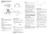
Please use the photos below to familiarize yourself with the components of
your new Magnum XL RFS series engine.
1
CAUTION - PLEASE READ!!
XL 1.80RFS
Global Services 18480 Bandilier Circle Fountain Valley, CA 92708 Phone: (714) 963-0329 Fax: (714) 964-6236 Email: service@globalhobby.com
ENGINE INSTALLATION
Engine Orientation
Your XL RFS series engine can be orientated in any position on the firewall.
Keep in mind that when the engine is mounted inverted, carburetor
adjustments will need to be made differently and the fuel tank may need to be
lowered. (See fuel tank size and orientation to carburetor on the next page.)
Features
●
Ringed-Piston Design for Long Life and High Power
●
Rear-Updraft, Dual-Needle Carburetor
●
High-Flow Quiet Muffler
●
Dual Ball Bearing-Supported Crankshaft & Camshaft
●
Dual Bushing-Supported Connecting Rod
SINGLE CYLINDER
FOUR-STROKE ENGINE
OPERATING INSTRUCTIONS
(P/N 210989)
XL 1.80RFS ENGINE SPECIFICATIONS
Displacement .......................... 29.52cc
Bore: ........................................ 36mm
Stroke: ..................................... 29mm
Practical RPM: ........................ 1,800 - 10,000
Weight w/Muffler: .................... 38.9oz
http://globalservices.globalhobby.com

2
For More Information on Magnum engines, Please Visit Our Website at http://globalservices.globalhobby.com
The engine should be mounted to either a heavy-duty, glass-filled nylon
engine mount, a machined aluminum engine mount or an integrated hardwood
beam mount. Use only high-quality steel cap screws and related hardware
to mount the engine to the engine mount. The firewall in the airplane should
be aircraft grade 5-ply plywood no less than 5/16" thick and the firewall should
be reinforced to meet the torque and weight of the engine.
Engine Bolts & Firewall Requirements
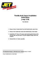
The muffler threads onto the exhaust pipe, which then threads into the engine's
cylinder head. First thread one cinch nut onto each end of the exhaust pipe,
then thread the muffler onto one
end. The muffler should be
threaded on at least 5/16" to
prevent vibration from damaging
the threads. Once you have
threaded the muffler onto the
exhaust pipe, use an open end
wrench to firmly tighten the cinch
nut up against the muffler. The
exhaust pipe is adjustable to
better suit the installation of your particular application. Thread the exhaust
pipe into the engine’s cylinder head. The exhaust pipe should be threaded
in no less than 5/16" to prevent vibration from damaging the threads in the
cylinder head. Once you have threaded the exhaust pipe into place and into
the proper position for your application, use an open end wrench to firmly
tighten the cinch nut against the cylinder head.
Muffler Installation
Ideally, the stopper in the fuel tank should be even with the high speed needle
valve or just slightly below it. Some models will only allow the fuel tank to be
mounted higher than the ideal location. A fuel tank that is positioned higher
than the ideal location usually doesn’t pose any problem except when it is
mounted excessively higher and/or is used in conjunction with an inverted
mounted engine or during extreme aerobatic flight. If you mount the engine
inverted, we strongly suggest lowering the fuel tank so the stopper assembly
is slightly below the high speed needle valve. Doing this will prevent fuel
from siphoning into the engine and flooding it when the fuel tank is full. If
you cannot lower the fuel tank far enough, we suggest lowering it as far as
can be allowed in your particular application.
The size of the fuel tank used should be 20oz. - 24oz., depending on the
model and the length of flights desired. Use of a 24oz. tank will provide
approximately 15 minutes of run time at full throttle. Use of a fuel tank any
larger than 24oz. can lead to excessive leaning of the engine during flight
and is not recommended.
Fuel Tank Size & Orientation to Carburetor
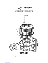
In some cases you may want the throttle arm on the opposite side of the
engine from how it comes
preinstalled. You can remove the
carburetor and reinstall it in the
opposite direction with no effect on
performance. To remove the
carburetor, loosen the two screws
holding the intake manifold in
place. Next, remove the two
screws holding the carburetor to the
engine and remove it by gently
pulling it down off the intake pipe. Installation is the reverse of disassembly.
Be careful not to damage the O-ring when reinstalling the carburetor.
Carburetor Orientation
Rotor Bolt
The rotor bolt holds the throttle barrel in the carburetor body and prevents
the throttle barrel from being over-rotated in either direction. It does not require
adjustment. Periodically check the rotor bolt to ensure that it is tight.
Optional Needle Valve Extension
If an extension is required to
adjust the high speed needle
valve, use a 1.5mm diameter wire
of the necessary length. Loosen
the grub screw in the side of the
needle valve (using a 1.5mm hex
wrench), insert the wire into the
end of the needle valve and
tighten the set screw firmly. If the
extension is more than 3" long we
recommend supporting the outer end of the extension to prevent excessive
vibration from damaging the needle valve assembly.
Crankcase Return Tube
A silicone crankcase return tube
is attached to the engine, between
the crankcase and the intake pipe.
This tube carries excess oil back
into the intake so it can be
redistributed thro ugh out the
engine. This system keeps the
engine better-lubricated. DO NOT
plug the tube or run the engine
without the tube attached.
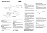
Propeller Installation
Your engine comes equipped with a main propeller nut and one safety nut.
For your safety, we recommend using both the propeller nut and the safety
nut to secure the propeller into place.
✦✦
✦✦
✦WARNING
✦✦
✦✦
✦ Before installing the propeller it must be properly balanced.
Running your engine using an out-of-balance propeller can lead to
excessive vibration, which will result in excessive stress and wear on both
the engine and the airframe. Balance the propeller using the method
recommended by the propeller manufacturer. Several products are
available to properly balance propellers. Ask your local retailer for more
information about these items.
The diameter of the crankshaft is 3/8". Using a 3/8" drill bit or a prop reamer,
enlarge the hole in the propeller
hub to fit the crankshaft. Slide the
propeller onto the crankshaft, up
against the drive washer. Slide
the propeller washer up against
the propeller and thread the main
prop nut into place. Tighten the
prop nut firmly to secure the propeller
into place, then install and tighten
the safety nut against the prop nut.
When tightening the nuts, use an adjustable wrench. Do not use pliers.
✦✦
✦✦
✦WARNING
✦✦
✦✦
✦ If you are installing a spinner onto your engine, the cone
of the spinner must not rub against the propeller. Allowing the spinner
cone to rub against the propeller could lead to propeller damage and
eventual propeller failure.
NOTE: EXHAUST PIPE THREAD SIZE IS M14x0.75mm
NOTE: PROPELLER SHAFT THREAD SIZE IS 3/8"-24

3
Global Services 18480 Bandilier Circle Fountain Valley, CA 92708 Phone: (714) 963-0329 Fax: (714) 964-6236 Email: service@globalhobby.com
The diameter and pitch of the propeller needed for your XL RFS series
engine will vary greatly depending on the application the engine is used in.
The weight, drag and the type of model and how you intend to fly it are all
factors in determining the correct size propeller to use. Experimentation
will be necessary to find the optimal size propeller for your particular
application. Ideally you want a propeller that will allow the engine to turn in
the 8,000 - 10,000 rpm range on the ground, yet power the airplane
sufficiently. Using a propeller that is too small will cause the engine to run at
too high an rpm. Using a propeller that is too large will cause the engine to
run at too low an rpm and cause it to lug down too much. In both instances
this can lead to premature engine wear and eventual failure.
PROPELLER SIZE RECOMMENDATIONS FOR XL 1.80RFS
Propeller Recommendation
Use for
Break-In
16 x 8
16 x 6
16 x 10
18 x 4-5
PROPELLER, GLOW PLUG & FUEL
Glow Plug Recommendation
We recommend using a hot heat-range glow plug intended specifically for
four-stroke engines. Do not use a cold heat-range plug or a plug designed
for two-stroke engines. This can lead to erratic engine runs and eventual
engine wear and failure. Thunderbolt 4-Stroke, O.S. Type-F and Fox
Miracle Plugs are good choices.
Fuel Recommendation
Fuel can make a big difference in the way your engine performs. We
recommend using two types of fuel with your XL RFS series engine. For the
break-in period you should use a fuel containing no more than 10% nitro
methane and no less than 18% Castor/synthetic blend lubricant. Use of fuel
containing more than the recommended percentage of nitro methane or only
synthetic lubricants will cause the engine to run too hot and result in excessive
wear and engine failure in a very short period of time. Once the engine has been
adequately broken in (about 1/2 gallon of the recommended break-in fuel),
a fuel containing 5% - 30% nitro methane and 16% -22% Castor or synthetic
blend lubricant fuel can be used.
✦✦
✦✦
✦WARNING
✦✦
✦✦
✦ For the break-in period, we do not recommend using fuel
that contains only synthetic lubricants. Synthetic lubricants have a much
lower flash point than Castor Oil lubricants. Flash point is the point at
which the lubricant begins to actually burn and lose its lubricating qualities.
Using fuel containing a blend of Castor Oil and synthetic lubricants results
in an engine that runs cooler and lasts longer. One lean run using a fuel
containing only synthetic lubricants can cause engine failure. Using fuels
with a Castor Oil and synthetic blend of lubricants greatly reduces this chance.
High Speed Needle Valve
The high speed needle valve is used to meter the air/fuel mixture at full
throttle. Turn the needle valve clockwise to lean the mixture or turn the needle
valve counterclockwise to richen the mixture. When you start the engine for
the very first time the needle valve should be turned in completely, then backed
out 2-1/2 turns. When you start the engine after that, leave the needle valve
in the same position it was in when you shut down the engine.
HIGH & LOW SPEED NEEDLE VALVES
Low Speed Needle Valve
The low speed needle valve is preset from the factory for initial starting and
break-in. Do not adjust it until after the engine is broken in. The low speed
needle valve regulates the air/fuel mixture at idle and during transition from
idle to full throttle. Turn the needle valve screw clockwise to lean the
mixture. Turn it counterclockwise to richen the mixture. The low speed
needle valve screw is preset from the factory, but minor adjustments may
need to be made after the engine is broken in. To reset the low speed
needle valve screw to the factory setting, follow these procedures:
●●
●●
●
Open the carburetor barrel completely.
●●
●●
●
While holding the barrel open, turn the needle valve screw IN
(clockwise) GENTLY until it stops. From this point, while still holding
the barrel open, turn the needle valve screw OUT (counter-clockwise)
2 full turns. This is the factory setting.
✦✦
✦✦
✦WARNING
✦✦
✦✦
✦ It is possible to turn the low speed needle valve screw so
lean that the engine will not draw fuel. The low speed needle valve screw
should not need to be adjusted more than one full turn in either direction
from the factory setting. If the engine does not idle or transition, reset the
low speed needle valve screw to the factory setting.
Your XL RFS series engine can be started using an electric starter or it can
be started by hand. For safety and ease of starting, especially when the
engine is new, we recommend using an electric starter. The following two
procedures should be done with the power to the glow plug off.
Starting Using an Electric Starter
When using an electric starter it is not necessary to choke and prime the
engine. The starter turns the engine over fast enough that the engine draws
fuel on its own. Priming the engine prior to using an electric starter can
cause the engine to "hydro-lock" or flood. This is a result of too much fuel in
the engine before it actually fires. Turning the engine over with an
electric starter while the engine is flooded can cause extreme damage
to the engine and/or cause the propeller assembly to come loose. Turn
the propeller through the compression stroke one time by hand to check
for a hydro-locked state before applying the starter.
STARTING PROCEDURE
Starting by Hand
When starting the engine by hand always use a chicken stick or a heavy
leather glove. Never just use your bare hand or serious injury could result.
To make the engine easier to start by hand it should first be primed. This is
done by opening the carburetor barrel completely and covering the tip of the
exhaust pipe with your finger. Fuel can then be drawn into the engine by
"pulling" the propeller through the compression stroke 2 - 3 times. This will
draw fuel into the engine. After fuel begins to enter the carburetor, remove
your finger from the exhaust pipe and pull the propeller through the
compression stroke once to check for a hydro-locked condition.
WARNING ABOUT ENGINE HYDRO-LOCKING
If the engine becomes hydro-locked, do not force the propeller through
the compression stroke. The excess fuel should be expelled from the
engine before attempting to start it.
●
Completely close the high speed needle valve until it bottoms out, then
remove the glow plug from the cylinder head.
●
With a rag over the top of the engine, turn the crankshaft several times,
using your electric starter or flipping the propeller by hand. The excess
fuel will be expelled out of the engine and into the rag.
●
Check to make sure that the glow plug has not been fouled, then reinstall it.
Reset the high speed needle valve.
18 x 6

4
For More Information on Magnum engines, Please Visit Our Website at http://globalservices.globalhobby.com
✦✦
✦✦
✦IMPORTANT
✦✦
✦✦
✦ Your XL RFS series engine is a ringed engine. A ringed
engine is designed differently from a typical ABC-designed engine that
you might be more familiar with; therefore, you will not feel much hesitation
as the piston moves through the top of the stroke. A ringed engine does
not have any taper in the sleeve. Ring tension is what seals the
combustion chamber. When the engine is brand new, it will not feel like it
has much compression. This is because the ring has not yet been seated
with the sleeve. After the engine has been broken in, compression will
increase. The break-in procedure will guide you through the steps
necessary to properly break in your new XL RFS series ringed engine.
Please follow the steps closely.
The break-in process allows the engine parts to perfectly fit each other and
properly protect each part from premature wear. The engine should be
broken in using a fuel that contains no more than 10% nitro methane and no
less than 18% Castor/synthetic blend lubricant. Fuel containing only
synthetic lubricants should not be used during the break-in procedure. For the
break-in procedure we recommend mounting the engine into the airplane it
will be used in. This way the muffler, fuel tank and throttle linkage can all be
tested in combination with the engine. If your airplane uses a cowling, it
should be removed during the break-in procedure.
❑ 1) Turn the high speed needle valve out 2-1/2 turns from the fully
closed position.
❑ 2) If you are using an electric starter to start the engine, follow the
procedure in the previous section. If you are starting the engine by hand,
follow that procedure in the previous section.
❑ 3) Open the throttle barrel to approximately 1/4 throttle. Connect the
power to the glow plug. Start the engine using an electric starter or by hand.
If starting by hand you will need to vigorously flip the propeller through the
compression stroke several times before the engine will start.
❑ 4) Once the engine starts, open the throttle barrel to about 1/2 throttle.
You may need to lean the high speed needle valve in about 1/4 turn to keep
the engine running at half throttle.
❑ 5) After the engine has been running about 1 minute, remove the power
from the glow plug and slowly advance the throttle barrel to full throttle.
Adjust the high speed needle valve so that the engine is running very rich.
You should notice excessive white smoke coming from the exhaust. Let the
engine run for approximately 10 minutes then stop the engine.
❑ 6) Let the engine cool for approximately 10 minutes then restart it. Set
the high speed needle valve mixture to a slightly leaner setting, about 1/4
turn more in. Let the engine run for about 5 minutes at this setting, then stop
the engine and let it cool for approximately 10 minutes.
❑ 7) Repeat the procedure in step # 6, while leaning the needle valve slightly
more each time. In all, you should run the engine about a total of 45 minutes
of actual running time. After 45 minutes of run-time the engine is ready for
flight. Fly the airplane with the engine set as rich as possible, but with
adequate power to fly the airplane. After each flight, lean the mixture slightly.
Continue to do this for about 5 flights. At this point the engine should hold a
good setting on the high speed needle valve and you can begin to fine tune
the needle valve settings to increase performance.
BREAK-IN PROCEDURE
Now that your engine is broken in, you can set the high and low speed needle
valves for optimum performance.
Please jump to the top of the next column.
OPTIMIZING THE MIXTURE SETTINGS
✦✦
✦✦
✦WARNING
✦✦
✦✦
✦ Be careful never to lean the engine out too much.
Remember that the lubricants for your engine are suspended in the fuel.
If you lean out the fuel mixture too much you will also be lowering the
amount of lubricant entering your engine. Less lubricant means more
chance of your engine overheating and possible engine failure.
Setting the High Speed Needle Valve
❑ 1) Start the engine and remove the power from the glow plug. Allow
the engine to warm up for about 30 seconds.
❑ 2) After the engine has warmed up, slowly lean the high speed mixture
until the engine reaches peak rpm. After reaching peak rpm, richen the
mixture slightly until an audible drop in rpm is heard. If you are using a
tachometer this should be between a 200 - 300 rpm drop.
❑ 3) With the engine running at full power, carefully lift the nose of the
airplane about 45º into the air. The mixture should not become too lean, but
you may hear a slight increase in rpm. If the engine sags, or loses rpm when
you hold the nose up, the mixture is too lean. If this is the case, slightly
richen the mixture and follow the test once more.
✦✦
✦✦
✦IMPORTANT
✦✦
✦✦
✦ Rpm will increase about 10% - 30% in the air. This is
due to the forward motion of the aircraft as it is flying. Because of this,
more air is entering the carburetor, at a higher force, which causes the
mixture to lean out. Additionally, as the fuel level in the fuel tank goes
down, fuel draw becomes more difficult for the engine, especially during
aerobatics, thus causing the mixture to go lean. It is imperative that you
set the mixture rich while on the ground to compensate for the
leaning tendencies that will happen in the air. Always watch the exhaust
during your flight. The engine should leave a noticeable white smoke trail
at all times. If there is no smoke trail, the engine is running too lean. You
should land immediately and reset the mixture.
Setting the Low Speed Needle Valve
❑ 1) Start the engine and lean out the high speed needle valve as per the
previous steps. Close the throttle until the slowest reliable idle is reached.
Allow the engine to idle for about 15 - 20 seconds.
❑ 2) Quickly advance the throttle to full. If the engine just stops running as
soon as the throttle is advanced, the idle mixture is too lean. With the
engine stopped, richen the idle mixture about 1/8 of a turn.
❑ 3) Repeat steps # 1 and # 2 until the engine will transition from idle to full
throttle smoothly. Minor hesitation in the transition is normal.
❑ 4) If you quickly advance the throttle from idle to full and the engine seems
to be very rich during transition (i.e., lots of smoke coming from the exhaust),
the mixture is too rich. With the engine stopped, lean the idle mixture about
1/8 of a turn.
❑ 5) Repeat steps # 1 and # 4 until the engine will transition from idle to full
throttle smoothly. Minor hesitation in the transition is normal.
Information about engine maintenance, including
adjusting the valves and returning your engine for
warranty service, can be found on the separate
sheets packaged with these Operating Instructions.
Magnum XL RFS series engines are distributed
exclusively by Global Hobby Distributors 18480 Bandilier
Circle, Fountain Valley, CA 92708
All contents copyright © 2005, Global Hobby
Distributors Version 1.0 August 2005

281160 Valve Tappet Lock Washer
281166 Needle Valve Holder Assembly
281170 Rotor Bolt
281308 Cam Gear Cover Bolt Set
281423 Cam Gear Ball Bearing
281506 Cylinder Head Bolt Set
281705 Carburetor Mounting Bolt Set
281803 High-Speed Needle Valve w/O-Ring
281804 Needle Valve Assembly - Complete
281901 Detent Spring
281903 Needle Valve Holder Gasket
282002 Fuel Nipple w/Gasket
282004 Fuel Nipple Only
282130 Throttle Barrel Spring
282310 Low-Speed Needle Valve w/O-Ring
282412 O-Ring for Low-Speed Needle Valve
282450 O-Ring for Pushrod Tube/HSNV
282501 Fuel Nipple Gasket Only
284020 Throttle Arm
284036 Front Ball Bearing
284037 Rear Ball Bearing
284085 E-Ring Retainer
284101 Backplate Bolt Set
284132 Exhaust Pipe w/Mounting Nuts
284137 Intake Pipe Mounting Bolts
284152 Backplate Gasket (Clear)
284157 Rocker Cover Bolt Set
284161 Drive Washer Set
284166 Woodruff Key
284206 Needle Valve Holder
284265 Valve Tappet Retaining Nut
284267 Valve Tappet Screw
284300 Crankcase
284301 Backplate
284302 Connecting Rod
284303 Crankshaft
284304 Wrist Pin & Retainer
284305 Propeller Washer
284306 Piston
284307 Cylinder Sleeve
284308 Piston Ring
284309 Propeller Nut & Safety Nut
284310 Muffler Assembly
284311 Muffler Only w/Nipple
284312 Rocker Cover
284313 Rocker Arm
284314 Cam Gear
284315 Carburetor Assembly
284316 Throttle Barrel
284317 Intake Pipe Gasket
284318 Carburetor Body w/Spray Bar
284319 Fuel Tubing
284320 Intake Pipe
284321 Bolt Set
284322 Pushrod
284323 Drive Washer Spacer
ENGINE REPLACEMENT
PARTS LIST
AND MAINTENANCE
GUIDE
284324 Gasket Set
284325 Valve Set (Intake & Exhaust)
284326 Rocker Arm Set
284327 Pushrod Assembly
284328 Cam Gear Cover w/Gasket
284329 Cylinder Head w/Valves
284330 Carburetor Mounting O-Ring
XL 1.80RFS
TO ORDER REPLACEMENT
PARTS, PLEASE VISIT YOuR
LOCAL MAGNUM ENGINE
DEALER FIRST. IF YOUR LOCAL
DEALER DOES NOT STOCK
MAGNUM ENGINE PARTS,
PLEASE CONTACT US DIRECTLY
Global Services
18480 Bandilier Circle
Fountain Valley, CA 92708
Phone: (714) 963-0329
Fax: (714) 964-6236
Email: service@globalhobby.net
http://globalservices.globalhobby.com
Revision 1 August 2005

This maintenance information is provided to help you keep your new XL RFS series aircraft engine running in top form. Following this
maintenance information will ensure the long life and dependability you expect from your engine.
The valve clearances are preset from the factory, but do require periodic
adjustment. Reset the valves after the first 1 hour of engine run-time.
After that, the valves can be checked and adjusted about every 8 hours of
run-time. The valves will need adjustment if you notice a severe loss of
power or after you have repaired and/or reassembled the engine.
✦✦
✦✦
✦IMPORTANT
✦✦
✦✦
✦ Always adjust the valves with the engine cold.
❑ 1) With the engine cold, remove the rocker cover on top of the cylinder
head by unscrewing the two socket-cap screws.
❑ 2) Rotate the crankshaft until the piston is at top-dead center. Both
valves will be closed at this point.
❑ 3) The required valve clearance is between .04mm and .10mm,
measured between the valve stem and the rocker arm. Use feeler gauges
to check the clearance. The .04mm feeler gauge should pass through the
gap with only slight friction. The .10mm feeler gauge should be tight.
❑ 4) Working with one valve at a time, loosen the locking nut, using a
small wrench. Use a screwdriver to turn the adjustment screw
counterclockwise about 1/2 turn. This will open the gap slightly. Slide the
.04mm feeler gauge between the rocker arm and the valve stem.
Carefully turn the adjustment screw clockwise until the rocker arm touches
the feeler gauge. Using a small wrench, tighten the lock nut.
❑ 5) Remove the feeler gauge and double-check the gap. Repeat step
# 4 if necessary to achieve the correct setting, then repeat the process for
the second valve assembly.
●
Use a high-quality after-run oil in the engine after you have purged the
engine of fuel. Inject the oil into the engine through the carburetor and
through the glow plug hole. Also, remove the fuel tubing from the intake
manifold and inject oil down into the cam gear. Rotate the crankshaft
several times to distribute the oil throughout the engine. This will prevent
rust from forming inside the engine, especially on the ball bearings.
●
Wipe the outside of the engine dry using a soft cloth.
●
Use a fuel filter between the fuel tank and the carburetor.
●
Periodically check to make sure all of the engine bolts are tight,
including the muffler and exhaust pipe cinch nuts.
●
Periodically check your fuel system, including the plumbing inside the
fuel tank, for leaks or cracks. We recommend changing the silicone fuel
tubing inside and outside the fuel tank at the start of every flying season or
about once a year.
Long-Term Storage
If you will not be using your engine for a long period of time, such as
during the winter, we suggest you take the following precautions to
preserve the reliability of your engine:
●
Run the engine completely dry of fuel as described above. This is
extremely important.
●
Remove the rocker cover and cam gear cover and apply a generous
amount of after-run oil on and around the rocker arm assembly and the
cam gear. Reinstall the covers.
●
Remove the engine backplate and apply a generous amount of
after-run oil to the engine crankcase and to the rear ball bearing, then
reinstall the backplate.
●
Apply a generous amount of after-run oil to the joint between the
carburetor barrel and the carburetor housing to prevent the barrel from
sticking.
●
Remove the glow plug and apply a generous amount of after-run oil
into the cylinder head. Reinstall the glow plug and turn the crankshaft
over several times to distribute the oil.
●
Once that is done, place the engine in a sealed baggie and remove as
much air from the baggie as possible. Your engine can now be stored for
a long period without worrying about rust or engine degradation.
Resetting the Timing
Engine maintenance should be done on a regular basis to ensure that you
keep the engine running in top form, especially over time. Following these
simple maintenance practices will ensure the long life and dependability
you expect from your engine.
●
Avoid running the engine under dusty conditions. If you are in a dusty
environment, we suggest using an air filter over the carburetor.
●
At the end of every flying day, purge the engine of fuel by disconnecting
the fuel line from the carburetor and allowing the engine to run dry of fuel.
The timing must be reset if the crankshaft and/or cam gear has been
disassembled. To reset the timing, rotate the crankshaft until the piston is
at top-dead center. (Verify this by looking through the glow plug hole.)
With the piston at top-dead center, install the cam gear with the small
punch mark facing toward you and pointing straight down toward the bottom
of the crankcase. Reinstall the cam gear cover and tighten the screws.
XL 1.80RFS ENGINE MAINTENANCE INFORMATION
ADJUSTING THE VALVES
MAINTENANCE

The following items are recommended for use with your XL RFS series
engine. These items are recommended for initial start-up and running.
Please read through the Operating Instructions for further details.
Fuel: We suggest Power Master 10% 2-Stroke Blend (P/N 275180) for
break-in.
We suggest Power Master 15% 4-Stroke Blend (P/N 275200) for
normal use.
We suggest using Power Master brand fuels. Power Master fuel comes in
10% and 15% nitromethane contents that can be used in your XL RFS
series engine. Power Master fuels are blended using only high-quality
nitromethane, methanol, Castor Oil and synthetic lubricants to provide
high power output, along with easy starting and unmatched lubricating
and heat dissipation qualities. For the extra lubrication necessary for
break-in, use 10% 2-stroke blend. After break-in, for extra performance,
use 15% 4-stroke blend.
Fuel Tank: Dubro 24oz. Fuel Tank (P/N 568576)
Dubro fuel tanks are a perfect match for your XL RFS series engine. This
size recommendation will give you approximately 15 minutes of run-time
at full throttle, and they are possibly the easiest fuel tanks to assemble
and maintain.
Glow Plug: Thunderbolt Four-Stroke Glow Plug (P/N 115490)
The Thunderbolt Four-Stroke glow plug is designed to be used in
four-stroke engines using fuels containing 5% - 30% nitro content and in
any environment. It is a "hot" type of glow plug for easy starting, excellent
transition and incredible top end. The glow plug is also very durable and
able to withstand repeated use, day after day.
Propeller: APC 16 x 8 Propeller (P/N 609780)
We have found that XL RFS series engines run best using APC brand
props. They are designed to be very efficient and run quiet at high rpm’s,
and they are also durable. Use this size prop to break in your engine,
then change to the prop that best suits your application. Use the guide in
the Operating Instructions to help you find the right size propeller.
Glow Starter: Magnum Glow Starter w/Meter (P/N 237438)
The Magnum glow starter is an excellent choice for heating the glow plug.
It uses a Sub-C NiCD, includes a meter to determine the quality of your
glow plug, and it also includes a charger to recharge the battery. It’s a
very economical product to purchase and can be used with any engine
that uses a glow plug.
Engine Mount: Magnum Aluminum Engine Mount (P/N 279950)
The Magnum adjustable engine mount is a heavy-duty aluminum beam
mount that mounts to a plywood firewall in the model. It is easy to install
and allows easy engine depth adjustment. This mount comes complete
with mounting hardware.
Engine Preparation
❑ 1) Mount the engine to the recommended engine mount. A strong
wood beam mount built into the airframe would also be sufficient.
❑ 2) Install the muffler and exhaust pipe onto the engine using the cinch
nuts provided. The exhaust pipe can be rotated to better suit the
installation in your model. Be sure to tighten the cinch nuts securely to
prevent the muffler and exhaust pipe from loosening.
❑ 3) Install the propeller to the engine using the propeller washer,
propeller nut and the safety nut provided. Tighten the nuts securely using
an adjustable wrench.
❑ 4) Connect the fuel lines to the carburetor and to the muffler. Make
sure that the silicone crankcase return tube is connected between the
crankcase nipple and the intake pipe nipple.
❑ 1) Carefully turn the high speed needle valve in completely until it stops,
then turn the needle valve out 2-1/2 turns. This is the mixture setting for
initial starting. Do not adjust the low speed needle valve. It's factory preset.
❑ 2) If hand starting, prime the engine by opening the throttle barrel
completely, covering the exhaust opening with your finger and flipping
the prop through compression 2 -3 times. If you will be using an electric
starter, do not prime the engine. The starter will turn the engine over
fast enough to draw fuel on its own.
❑ 3) Connect the glow starter to the glow plug. Open the carburetor
barrel to about 1/4 throttle and start the engine. If you are starting the
engine by hand, you will need to vigorously flip the prop several times
before the engine will start. Once the engine begins running, immediately
turn the high speed needle valve in about a 1/4 turn to keep the
engine running.
❑ 4) Advance the throttle to full while turning the high speed needle valve
in to keep the engine running. The engine should be producing a very
noticeable white exhaust from the muffler and sound like it is running rough.
Allow the engine to run for only about 5 minutes, then shut the engine off.
❑ 5) Now that you have started your engine, it must be properly broken
in. Proper break-in will seat all of the moving parts, particularly the piston
ring, sleeve and valve assemblies. This procedure takes about 45
minutes of run-time and is highly recommended. An engine that is properly
broken in will produce more power, be more user-friendly and last much
longer than an engine that does not receive a break-in period. For this
reason we highly recommend following the break-in procedure detailed
in the Operating Instructions before you run the engine further.
Engine Starting
The following information is provided to get your new Magnum XL RFS
series engine running right away with minimal effort. We have listed
our recommendations for fuel, propeller, starting procedures and
other recommended accessories. Also included is general information
about the accessories needed for the engine that we hope you will
find helpful.
This Quick-Start Guide should not be used as a replacement for the
Operating Instructions included; rather, it should be used along with
the Operating Instructions. We highly recommend reading through
the Operating Instructions to familiarize yourself with each part of the
engine, along with the proper procedures for engine break-in and tuning.
XL 1.80RFS
AIRCRAFT ENGINE QUICK-START AND
TROUBLESHOOTING GUIDE
(Warranty Information on Back)
OUR RECOMMENDATIONS
QUICK-STARTING PROCEDURES

1) Engine does not start A) Failed glow plug A) Replace glow plug with new one
B) Glow starter not charged and/or faulty B) Fully charge glow starter and/or replace
C) Engine not being turned over fast enough C) Use an electric starter to start engine
D) Low speed needle valve set too lean D) Reset low speed needle valve to factory setting
E) Old or contaminated fuel E) Replace with new fuel
F) Engine flooded with too much fuel F) Remove glow plug and expel fuel from cylinder
G) Faulty fuel tank and/or stopper assembly G) Check and/or replace fuel tank assembly
H) Air leak in fuel system and/or engine H) Replace fuel lines and/or tighten all engine bolts
I) Valves out of adjustment I) Readjust valves to proper setting
2) Engine does not draw fuel A) Air leak in fuel system and/or engine A) Replace fuel lines and/or tighten all engine bolts
B) High speed needle valve fully closed B) Reset high speed needle valve to factory setting
C) Low speed needle valve set too lean C) Reset low speed needle valve to factory setting
D) Fuel lines kinked D) Check and straighten fuel lines
E) Defective fuel tank E) Replace fuel tank
3) Engine vibrates excessively A) Propeller out of balance A) Balance propeller
B) Engine and/or engine mount loose B) Tighten engine mounting bolts
4) Engine does not transition A) Failed and/or wrong type glow plug A) Replace with new recommended glow plug
B) Old and/or wrong type fuel B) Replace with new recommended fuel
C) High speed needle valve set too rich C) Set high speed needle valve to leaner setting
D) Low speed needle valve set too lean D) Set low speed needle valve richer
E) Low speed needle valve set too rich E) Set low speed needle valve leaner
F) Air leak in fuel system and/or engine F) Replace fuel lines and/or tighten all engine bolts
G) Propeller too large G) Replace with one size smaller propeller
H) Valves out of adjustment H) Readjust valves to proper setting
5) Throttle barrel does not A) Throttle servo linkage out of adjustment A) Adjust throttle linkage to close throttle barrel
close completely completely
6) Engine overheats A) Engine running too lean A) Richen high speed needle valve
B) Cowl too restrictive B) Open larger vents in cowling to allow air to exit
C) Wrong type of fuel used C) Use fuel with recommended oil content
D) Engine not fully broken in D) Allow engine further break-in time
7) Engine stops abruptly A) Engine running too lean A) Richen high speed needle valve
B) Piston Ring & sleeve out of tolerances B) Return engine to Global Services
C) Engine Overheating C) See # 6 above
PROBLEM CAUSE SOLUTION
All Magnum engines returned for warranty service must be within the warranty terms as stated on the warranty card provided with your engine. Do not
return the engine to the place of purchase. They are not authorized or equipped to perform warranty work on Magnum products. When requesting
warranty service, please observe the following guidelines:
●
Always send the complete engine including the carburetor and muffler. The engine must be removed from the model.
●
Include a note detailing the problem or service you are requesting. Service cannot be provided without this information. Include your daytime
phone number in the event we need more details pertaining to the service requested.
●
You may request an estimate of services at the time you return your engine for service. An omission of this request implies permission for the
Magnum Service Center to service your engine at our discretion.
●
Include a method of payment for any service charges. If not specified, the unit will be returned to you C.O.D.
●
Send the engine to us by United Parcel Service, Federal Express or by Insured Mail. Postage is not refundable. Send to:
Global Services
●●
●●
●
18480 Bandilier Circle
●●
●●
●
Fountain Valley, CA 92708
Phone (714) 963-0329
●●
●●
●
Fax (714) 964-6236
●●
●●
●
Email: service@globalhobby.com
This troubleshooting guide has been provided to help you diagnose and solve most problems that you may encounter with your XL RFS
series engine. Most problems encountered can be solved by carefully following the problem-cause-solution sections below. If you
cannot solve the problem using this troubleshooting guide, please feel free to contact us at the address or phone number listed below.
RETURNING YOUR ENGINE FOR WARRANTY SERVICE
/