Page is loading ...

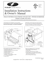
TURBINE POWERED HUMIDIFIER
Model: TB-1
The TurboMist™ distributes moisture via a rotating foam system
powered by air movement in the furnace plenum. The foam pick
up water carried in the unit and disperse moisture into the air.
DO NOT DESTROY
THESE INSTRUCTIONS MUST REMAIN WITH EQUIPMENT
English .......Page 1
Français .....Page 5
Espanõl ......Page 8
PRODUCT QUESTIONS…
CALL FIELD FIRST
Phone: (252)522-3031
E-mail:
for answers on product maintenance,
operation or replacement part questions.

Page 2
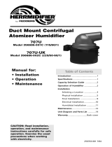
Shaded portions indicate dead or turbulent air.
CAUTION: Do not use the TurboMist™ in a down-flow furnace. (The
type where the heated air output is from the bottom of the furnace.)
INSTALLATION
Refer to Figure 1 and Figure 2 for suggested humidifier locations. Do not
install in a turbulent or dead air space. In installations where more than
one humidifier is used do not place them in a position so that one
obstructs the air flow of the other.
WARNING: Locate the A-COIL before cutting into plenum
chamber.
1. Locate the humidifier as close to an existing water pipe as possible.
(DO NOT INSTALL SADDLE VALVE on any water pipe which is
downstream from a water softener.) Insert baffle if air flow is not
directed properly to make turbine and evaporator revolve. See Figure
2
2. Disassemble humidifier: Pull off cover. Remove bagged float valve
assembly. Remove pan by lifting up and out. (See Figures 3 & 4)
Refer to Figure 5:
3. Peel backing from template sheet and apply to duct or plenum.
4. See instructions on installation template. Drill four 3/32" dia. Holes.
Cut opening in duct as indicated.
5. Use four screws furnished to attach humidifier body to duct. Place
level in humidifier body to make sure humidifier is level front to
back. Shim with thin metal washers at the front flange as
necessary.
Figure 1
Figure 2
Figure 3
Figure 4
Figure 5

Page 3
REASSEMBLE HUMIDIFIER: (FIGURES 6 & 7)
1. Place evaporator assembly and pan into humidifier body
making sure evaporator shaft fits into drive hub.
2. Attach float and arm assembly by inserting bracket into
mounting hole in the body of humidifier. Insert #8-32 hex
head screw provided in bagged hardware and tighten into
place.
3. Connect water supply from the saddle valve to the
TurboMist™ valve. (Figures 7 & 8)
INSTALLATION OF SADDLE VALVE ON COPPER TUBE
(FIGURE 8)
CAUTION: Do not turn handle before or while installing the
"saddle tapping valve." Be sure the piercing lance does not
protrude beyond the rubber gasket. Failure to do this may
result in damage to the piercing needle.
1. Assemble the "Saddle Tapping Valve" on copper tube
with enclosed bolt and nuts.
2. Tighten bolts evenly and firmly. Brackets should be
parallel.
3. Make the water connection to the outlet of the "Saddle
Tapping Valve."
4. Turn the handle clockwise until you feel it is firmly seated.
NOTE: You have now pierced the copper tube and the valve is
closed.
5. After completing all installation steps turn the handle
counter-clockwise to open the valve.
NOTE: See saddle valve assembly package for additional
instructions.
6. Turn water on at saddle valve. Be sure float does not touch any part of the pan and is free to move up and
down. The rising and lowering of the float will automatically shut off or replenish the water supply.
7. Check system for leaks. Install front cover.
8. A 1/4" diameter tube should be inserted into the water overflow hole in the pan (See Figure 4) for any
excess water drainage.
Figure 6
Figure 8
Figure 7

Page 4
MAINTENANCE
Your Field TurboMist™ Humidifier puts pure water in the air and traps impurities on the evaporator discs and in
the water pan. At the end of each heating season the water pan and float should be cleaned and the saddle
valve turned off. Do not use sharp objects or harsh abrasives to clean pan and float.
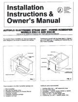
REPLACEMENT PARTS
The float valve assembly, evaporator assembly and saddle valve assembly can be obtained as replacement
parts as necessary. Refer to the diagram below for description.
• For current pricing or to place an order, go to Field Control’s website or call Field Control’s
Customer Service at 252-522-3031.
• VISA and MasterCard orders ONLY. No checks, cash, COD’s, or money orders will be
accepted.
Accessory Parts List
Float Valve Assy 46242700
Evaporator Assembly 46244100
Saddle Valve Assembly 46007300
Turbine Assembly 46235700
/