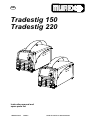
Murex Tradestig 220 User manual
- Category
- Welding System
- Type
- User manual
This manual is also suitable for

GB
Valid for serial no. 827-xxx-xxxx0460 474 074 100217
Tradestig 150
Tradestig 220
Instruction manual and
spare parts list

- 2 -
TOCe
Rights reserved to alter specifications without notice.
1 DIRECTIVE 3. . . . . . . . . . . . . . . . . . . . . . . . . . . . . . . . . . . . . . . . . . . . . . . . . . . . . . . .
2 SAFETY 3. . . . . . . . . . . . . . . . . . . . . . . . . . . . . . . . . . . . . . . . . . . . . . . . . . . . . . . . . . .
3 INTRODUCTION 5. . . . . . . . . . . . . . . . . . . . . . . . . . . . . . . . . . . . . . . . . . . . . . . . . . .
4 TECHNICAL DATA 5. . . . . . . . . . . . . . . . . . . . . . . . . . . . . . . . . . . . . . . . . . . . . . . . .
5 INSTALLATION 7. . . . . . . . . . . . . . . . . . . . . . . . . . . . . . . . . . . . . . . . . . . . . . . . . . . .
5.1 Location 7. . . . . . . . . . . . . . . . . . . . . . . . . . . . . . . . . . . . . . . . . . . . . . . . . . . . . . . . . . . . . . . . . .
5.2 Mains power supply 7. . . . . . . . . . . . . . . . . . . . . . . . . . . . . . . . . . . . . . . . . . . . . . . . . . . . . . . .
6 OPERATION 8. . . . . . . . . . . . . . . . . . . . . . . . . . . . . . . . . . . . . . . . . . . . . . . . . . . . . . .
6.1 PFC - Power factor correction 8. . . . . . . . . . . . . . . . . . . . . . . . . . . . . . . . . . . . . . . . . . . . . . .
6.2 Connections and control devices 8. . . . . . . . . . . . . . . . . . . . . . . . . . . . . . . . . . . . . . . . . . . .
6.3 Key to symbols 8. . . . . . . . . . . . . . . . . . . . . . . . . . . . . . . . . . . . . . . . . . . . . . . . . . . . . . . . . . . .
6.4 MMA-welding 9. . . . . . . . . . . . . . . . . . . . . . . . . . . . . . . . . . . . . . . . . . . . . . . . . . . . . . . . . . . . .
6.5 Overheating protection 9. . . . . . . . . . . . . . . . . . . . . . . . . . . . . . . . . . . . . . . . . . . . . . . . . . . . .
6.6 Turning on the power source 9. . . . . . . . . . . . . . . . . . . . . . . . . . . . . . . . . . . . . . . . . . . . . . . .
7 CONTROL PANELS 9. . . . . . . . . . . . . . . . . . . . . . . . . . . . . . . . . . . . . . . . . . . . . . . .
7.1 Tradestig 150 10. . . . . . . . . . . . . . . . . . . . . . . . . . . . . . . . . . . . . . . . . . . . . . . . . . . . . . . . . . . . .
7.2 Tradestig 220 11. . . . . . . . . . . . . . . . . . . . . . . . . . . . . . . . . . . . . . . . . . . . . . . . . . . . . . . . . . . . .
8 TIG WELDING 12. . . . . . . . . . . . . . . . . . . . . . . . . . . . . . . . . . . . . . . . . . . . . . . . . . . . .
8.1 Settings 12. . . . . . . . . . . . . . . . . . . . . . . . . . . . . . . . . . . . . . . . . . . . . . . . . . . . . . . . . . . . . . . . . .
8.2 Symbol and Function explanations TIG 12. . . . . . . . . . . . . . . . . . . . . . . . . . . . . . . . . . . . . . .
8.3 Hidden TIG functions 16. . . . . . . . . . . . . . . . . . . . . . . . . . . . . . . . . . . . . . . . . . . . . . . . . . . . . .
9 MMA WELDING 17. . . . . . . . . . . . . . . . . . . . . . . . . . . . . . . . . . . . . . . . . . . . . . . . . . . .
9.1 Settings 17. . . . . . . . . . . . . . . . . . . . . . . . . . . . . . . . . . . . . . . . . . . . . . . . . . . . . . . . . . . . . . . . . .
9.2 Symbol and Function explanations MMA 17. . . . . . . . . . . . . . . . . . . . . . . . . . . . . . . . . . . . . .
9.3 Hidden MMA functions 18. . . . . . . . . . . . . . . . . . . . . . . . . . . . . . . . . . . . . . . . . . . . . . . . . . . . .
10 WELDING DATA MEMORY 19. . . . . . . . . . . . . . . . . . . . . . . . . . . . . . . . . . . . . . . . . .
11 FAULT CODES 19. . . . . . . . . . . . . . . . . . . . . . . . . . . . . . . . . . . . . . . . . . . . . . . . . . . .
12 MAINTENANCE 20. . . . . . . . . . . . . . . . . . . . . . . . . . . . . . . . . . . . . . . . . . . . . . . . . . . .
12.1 Inspection and cleaning 20. . . . . . . . . . . . . . . . . . . . . . . . . . . . . . . . . . . . . . . . . . . . . . . . . . . .
13 FAULT-TRACING 20. . . . . . . . . . . . . . . . . . . . . . . . . . . . . . . . . . . . . . . . . . . . . . . . . .
14 ORDERING SPARE PARTS 21. . . . . . . . . . . . . . . . . . . . . . . . . . . . . . . . . . . . . . . . .
15 DISMANTLING AND SCRAPPING 21. . . . . . . . . . . . . . . . . . . . . . . . . . . . . . . . . . .
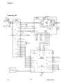
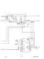
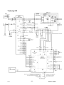
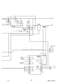
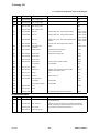
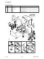
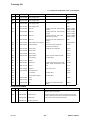
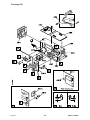
DIAGRAM 22. . . . . . . . . . . . . . . . . . . . . . . . . . . . . . . . . . . . . . . . . . . . . . . . . . . . . . . . . . . .
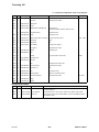
SPARE PARTS LIST 27. . . . . . . . . . . . . . . . . . . . . . . . . . . . . . . . . . . . . . . . . . . . . . . . . .
ACCESSORIES 38. . . . . . . . . . . . . . . . . . . . . . . . . . . . . . . . . . . . . . . . . . . . . . . . . . . . . . .

- 3 -
bt35d1ea
1 DIRECTIVE
DECLARATION OF CONFORMITY
Murex Welding Products Ltd, EN8 7TF England, gives its unreserved guarantee that welding power
source Tradestig 150 and Tradestig 220 from serial number 827 (2008 w 27) are contructed and
tested in compliance with the standard EN 60974-1 /-3 and EN 60974-10 (Class A) in accordance with
the requirements of directive (2006/95/EC) and (2004/108/EEC).
-------------------------------------------------------------------
Kent Eimbrodt
Global Director
Equipment and Automation
On behalf of Murex Welding Products Ltd.
Laxå 2008-08-28
Manufactured by ESAB AB, Welding Equipment
SE-695 81 Laxå Sweden
2 SAFETY
Users of welding equipment have the ultimate responsibility for ensuring that anyone who works on
or near the equipment observes all the relevant safety precautions. Safety precautions must meet
the requirements that apply to this type of welding equipment. The following recommendations
should be observed in addition to the standard regulations that apply to the workplace.
All work must be carried out by trained personnel well-acquainted with the operation of the welding
equipment. Incorrect operation of the equipment may lead to hazardous situations which can result
in injury to the operator and damage to the equipment.
1. Anyone who uses the welding equipment must be familiar with:
S its operation
S location of emergency stops
S its function
S relevant safety precautions
S welding
2. The operator must ensure that:
S no unauthorized person is stationed within the working area of the equipment when it is
started up.
S no-one is unprotected when the arc is struck
3. The workplace must:
S be suitable for the purpose
S be free from drafts
4. Personal safety equipment
S Always wear recommended personal safety equipment, such as safety glasses, flame-proof
clothing, safety gloves. Note! Do not use safety gloves when replacing wire.
S Do not wear loose-fitting items, such as scarves, bracelets, rings, etc., which could become
trapped or cause burns.
5. General precautions
S Make sure the return cable is connected securely.
S Work on high voltage equipment may only be carried out by a qualified electrician.
S Appropriate fire extinquishing equipment must be clearly marked and close at hand.
S Lubrication and maintenance must not be carried out on the equipment during operation.
GB

- 4 -
bt35d1ea
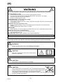
WARNING
Read and understand the instruction manual before installing or operating.
Arc welding and cutting can be injurious to yourself and others. Take precausions when welding.
Ask for your employer's safety practices which should be based on manufacturers' hazard data.
ELECTRIC SHOCK - Can kill
S Install and earth the welding unit in accordance with applicable standards.
S Do not touch live electrical parts or electrodes with bare skin, wet gloves or wet clothing.
S Insulate yourself from earth and the workpiece.
S Ensure your working stance is safe.
FUMES AND GASES - Can be dangerous to health
S Keep your head out of the fumes.
S Use ventilation, extraction at the arc, or both, to take fumes and gases away from your breathing zone
and the general area.
ARC RAYS - Can injure eyes and burn skin.
S Protect your eyes and body. Use the correct welding screen and filter lens and wear protective
clothing.
S Protect bystanders with suitable screens or curtains.
FIRE HAZARD
S Sparks (spatter) can cause fire. Make sure therefore that there are no inflammable materials nearby.
NOISE - Excessive noise can damage hearing
S Protect your ears. Use earmuffs or other hearing protection.
S Warn bystanders of the risk.
MALFUNCTION - Call for expert assistance in the event of malfunction.
PROTECT YOURSELF AND OTHERS!
Murex can provide you with all necessary welding protection and accessories.
WARNING!
Do not use the power source for thawing frozen pipes.
CAUTION!
Read and understand the instruction manual before
installing or operating.
CAUTION!
This product is solely intended for arc welding.
CAUTION!
Class A equipment is not intended for use in residential locations where
the electrical power is provided by the public low-voltage supply system.
There may be potential difficulties in ensuring electromagnetic
compatibility of class A equipment in those locations, due to conducted
as well as radiated disturbances.
GB

- 5 -
bt35d1ea
3 INTRODUCTION
The Tradestig 150 / Tradestig 220 is a TIG welding power source, which can also
be used for MMA welding. It can be used direct current (DC).
MUREX's accessories for the product can be found on page 38.
Equipment
The power source is supplied with a 3 m welding cable, 3 m return cable, 3 m mains
cable, instruction manual for power source and control panel.
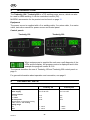
Control panels
Tradestig 150 Tradestig 220
When mains power is supplied the unit runs a self diagnosis of the
LEDs and the display, the program version is displayed and in this
example the program version is 0.18.
The manual describes the use of Tradestig 150 and Tradestig 220 control panel on
page 9.
For general information about operation and connection, see page 8
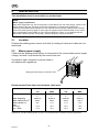
4 TECHNICAL DATA
Tradestig 150 Tradestig 220
Mains voltage 230V, $10%, 1 50/60 Hz 230V, $10%, 1 50/60 Hz
Mains supply Z
max
0.35 ohm Z
max
0.31 ohm
Primary current
I
max
TIG
I
max
MMA
14 A
22 A
24 A
25 A
No-load power
demand when in the energy-saving
mode, 6.5 min. after welding
30 W 30 W
Setting range
TIG
MMA
3 - 150 A
4 - 150 A
3 - 220 A
4 - 170 A
GB

- 6 -
bt35d1ea
Tradestig 220Tradestig 150
Ignition voltage (U
pk
) 11.5 kV 11.5 kV
Permissible load at TIG
20% duty cycle
25% duty cycle
60% duty cycle
100% duty cycle
150 A / 16.0 V
120 A / 14.8 V
110 A / 14.4 V
220 A / 18.8 V
150 A / 16.0 V
110 A / 14.4 V
Permissible load at MMA
25% duty cycle
60% duty cycle
100% duty cycle
150 A / 26.0 V
100 A / 24.0 V
90 A / 23.6 V
170 A / 26.8 V
130 A / 25.2 V
110 A / 24.4 V
Power factor at maximum current
TIG
MMA
0.98
0.99
0.99
0.99
Efficiency at maximum current
TIG
MMA
77 %
80 %
75 %
81 %
Open-circuit voltage TIG
with VRD
55 - 60 V
< 35 V
55 - 60 V
< 35 V
Open-circuit voltage MMA
with VRD
55 - 60 V
< 35 V
55 - 60 V
< 35 V
Operating temperature -10 to + 40° C -10 to + 40° C
Transportation temperature -20 to + 55° C -20 to + 55° C
Constant sound pressure in
open-circuit
< 70 dB (A) < 70 dB (A)
Dimensions, l x b x h 418 x 188 x 208 mm 418 x 188 x 208 mm
Weight 9.2 kg 9.4 kg
Shielding gas
max pressure
All types intended for TIG
welding
5 bar
All types intended for TIG
welding
5 bar
Insulation class transformer H H
Enclosure class IP 23 IP 23
Application class
Duty cycle
The duty cycle refers to the time as a percentage of a ten-minute period that you can weld at a cer
tain load without overloading. The duty cycle is valid for 40° C.
The duty cycle is valid for 40° C ambient temperature.
Enclosure class
The IP code indicates the enclosure class, i. e. the degree of protection against penetration by solid
objects or water. Equipment marked IP23 is designed for indoor and outdoor use.
Application class
The symbol indicates that the power source is designed for use in areas with increased
electrical hazard.
Mains supply, Z
max
Maximum permissible line impedance of the network in accordance with IEC 61000-3-11.
GB

- 7 -
bt35d1ea
5 INSTALLATION
The installation must be executed by a professional.
Note!
Mains supply requirements
High power equipment may, due to the primary current drawn from the mains supply, influence the
power quality of the grid. Therefore connection restrictions or requirements regarding the
maximum permissible mains impedance or the required minimum supply capacity at the interface
point to the public grid may apply for some types of equipment (see technical data). In this case it
is the responsibility of the installer or user of the equipment to ensure, by consultation with the
distrubution network operator if necessary, that the equipment may be connected.
5.1 Location
Position the welding power source such that its cooling air inlets and outlets are not
obstructed.
5.2 Mains power supply
Check that the welding power source is connected to the correct mains power supply
voltage, and that it is protected by the correct fuse size.
A protective earth connection must be made in
accordance with regulations.
Rating plate with supply connection data
Recommended fuse sizes and minimum cable area
Tradestig 150 Tradestig 220
TIG MMA TIG MMA
Mains voltage 230 V 10 %,
1
230 V 10 %,
1
230 V 10 %,
1
230 V 10 %,
1
Mains frequency 50/60 Hz 50/60 Hz 50/60 Hz 50/60 Hz
Mains cable area mm
2
3G2.5 3G2.5 3G2.5 3G2.5
Phase current I
1eff
9 A 11 A 11 A 14 A
Fuse
anti-surge
type C MCB
16 A
13 A
16 A
13 A
16 A
16 A
16 A
16 A
NOTE! The mains cable areas and fuse sizes as shown above are in accordance with Swedish
regulations. Use the welding power source in accordance with the relevant national regulations.
GB

- 8 -
bt35d1ea
6 OPERATION
General safety regulations for the handling of the equipment can be found on
page 3. Read through before you start using the equipment!
6.1 PFC - Power factor correction
The Tradestig is 230 V single-phase power sources equipped with a PFC circuit
making it possible to use the full range of the machine on a 16 A fuse. The PFC also
protects the machines against fluctuating mains voltage and makes it safer to use
with a generator. Tradestig can operate with extra long mains cables, over 100 m,
giving you a very larger working radius.
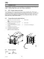
6.2 Connections and control devices
1 Connection (+) for the return cable for
TIG.
MMA: for the return cable or the welding
cable.
7 Mains switch
2 Connection for the remote control unit,
only with Tradestig 220
8 Mains cable
3 Control panel (see separate instruction
manual)
9 Connection for shiedling gas
4 Connection for the TIG-torch
5 Connection for gas to the TIG-torch
6 Connection (-) for the TIG-torch
MMA: return cable or welding cable
6.3 Key to symbols
MMA TIG
GB

- 9 -
bt35d1ea
6.4 MMA-welding
Connection of welding and return cable
The welding power source has two terminals, one plus and one minus pole, for the con
nection of the welding and the return cable. Connect the welding cable to the pole indi
cated on the package of the electrode to be used.
Connect the return cable to the other terminal. Fit the earth clamp of the return cable
to the work-piece and make sure there is good contact between the work-piece and the
return cable terminal on the welding power source.
6.5 Overheating protection
The power source has two thermal overload trips which operate if the internal
temperature becomes too high. A fault code is shown in the panel. They reset
automatically when the temperature has fallen.
6.6 Turning on the power source
Turn on the mains power by turning the mains switch to the ”1” position.
Turn the unit off by turning the switch to the ”0” position.
Whether the mains power supply is interrupted or the power unit is switched off in
the normal manner, welding data will be stored and is available next time the unit is
started.
7 CONTROL PANELS
When mains power is supplied the unit runs a self diagnosis of the
LEDs and the display, the program version is displayed and in this
example the program version is 0.18.
VRD (Voltage Reduction Device)
The VRD function ensures that the open-circuit voltage does not exceed 35 V when
welding is not being carried out. This is indicated by a lit VRD LED. The VRD
function is deactivated when the system senses that welding has started.
If the VRD function is activated and open-circuit voltage exceeds the 35 V limit, this
is indicated by an error message (16) appearing in the display and welding cannot
be started whilst the error message is displayed.
NOTE! The VRD function is not active (LED has gone out) on delivery. Contact an
authorised ESAB service technician to activate the function.
GB

- 10 -
bt35d2ea
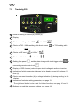
7.1 Tradestig 150
Knob for setting data (current (A), time (s) or material thickness (mm/inch))
Display
Choice of welding method TIG or MMA
Choice of selection of HF start or LiftArct start
Choice of 2-stroke or 4-stroke
Display of VRD function (reduced open-circuit voltage) is active or inactive..
Indication of which parameter is shown in the display, current (A), time (s) or
material thickness (mm/inch)
Choise for selection of setting parameter,
material thickness , slope down or gas post flow .
Note! The pushbutton is also used for hidden functions, see on page 16.
GB

- 11 -
bt35d2ea
7.2 Tradestig 220
Knob for setting of current (A) or time (s)
Display
Choice of welding method TIG eller MMA
Choice of TIG- / MMA-welding with direct current or TIG-welding with
pulsed current
Choice of HF start or LiftArct
Choice of 2-stroke or 4-stroke
Setting from panel , welding data change with torch trigger switch or
connecting remote control unit
Display of VRD-function (reduced open-circuit voltage) is active or inactive.
Indication of which parameter is shown in the display current (A), voltage (V),
time (s)
Choice of current indication (A) or voltage indication (V) during welding, in the
display.
Indication of selected setting parameter, see page 13.
The right-hand button is also used for hidden functions, see page 16 and 18.
Buttoms for weld data memory settings, see page 19.
GB

- 12 -
bt35d2ea
8 TIG WELDING
8.1 Settings
Function Setting range Tradestig
150
Tradestig
220
HF / LiftArc t
2)
HF or LiftArct x x
2/4-stroke
2)
2 stroke or 4 stroke x x
Gas pre flow time
1)
0 - 5 s x x
Slope up-time
1)
0 - 10 s x x
Slope down time 0 - 10 s x x
Gas post flow time 0 - 25 s x x
Current 4 - max
3)
x x
Active panel OFF or ON - x
Changing trigger data OFF or ON - x
Remote control unit OFF or ON - x
Min current remote
1)
0-99% - x
Pulse current 4 - max
3)
x x
Pulse time
Micro pulse
1)
0.01 - 2.5 s
0.001 - 0.250 s
- x
Background current 4 - max
3)
- x
Background time
Micro pulse
1)
0.01 - 2.5 s
0.001 - 0.250 s
- x
Material thickness
3)
30 A/mm in step of 0.1 mm x -
1)
These functions are hidden Tig functions, see description point 8.3.
2)
These functions cannot be changed while welding is in progress
3)
The setting range is depended on the power source used.
8.2 Symbol and Function explanations TIG
TIG welding
TIG welding melts the metal of the workpiece, using an arc struck from a tungsten elec
trode, which does not melt itself. The weld pool and the electrode are protected by
shielding gas.
Direct current
A higher current gives a wider weld pool, with better penetration into the workpiece.
Pulsed current
Pulsing is used for improved control of the weld pool and the solidification process.
The pulse frequency is set so slow that the weld pool has time to solidify at least
partially between each pulse. In order to set pulsing, four parameters are required:
pulse current, pulse time, background current and background time.
GB

- 13 -
bt35d2ea
Parameter settings
1. Slope up
2. Welding current
3. Pulse time
4. Background current
5. Background time
6. Slope down
7. Gas post flow time
Slope up
The slope up function means that, when the TIG arc strikes, the current rises slowly
to the set value. This provides `gentler' heating of the electrode, and gives the
welder a chance to position the electrode properly before the set welding current is
reached.
Pulse current
The higher of the two current values in the event of pulsed current.
Current Background time
Pulse current
Background
current
Pulse time
Time
TIG welding with pulsing.
Pulse time
The time the pulse current is on during a pulse period.
Background current
The lower of the two current values in the event of pulsed current.
Background time
Time for background current which, along with the time for pulse current, gives the
pulse period.
Slope down
TIG welding uses “slope down”, by which the current falls 'slowly' over a controlled
time, to avoid craters and/or cracks when a weld is finished.
Gas post-flow
This controls the time during which shielding gas flows after the arc is extinguished.
HF
The HF function strikes the arc by means of a spark from the electrode to the
workpiece as the electrode is brought closer to the workpiece.
GB

- 14 -
bt35d2ea
LiftArct
The LiftArct function strikes the arc when the electrode is brought into contact with
the workpiece and then lifted away from it.
Striking the arc with the LiftArc functiont. Step 1: the electrode is touched on to the workpiece.
Step 2: the trigger switch is pressed, and a low current starts to flow. Step 3: the welder lifts the
electrode from the workpiece: the arc strikes, and the current rises automatically to the set value.
2-stroke
With 2-stroke gas pre-flow (if used) starts when the welding gun trigger switch is
pressed. The welding process then starts. Releasing the trigger switch stops weld
ing entirely and starts gas post-flow (if selected).
Gas pre-flow Slope
up
Slope down Gas post-flow
Functions when using 2 stroke control of the welding torch.
In the 2 stroke control mode, pressing the TIG torch trigger switch (1) starts gas
pre-flow (if used) and strikes the arc. The current rises to the set value (as controlled
by the slope up function, if in operation). Releasing the trigger switch (2) reduces the
current (or starts slope down if in operation) and extinguishes the arc. Gas post-flow
follows if it is in operation.
GB

- 15 -
bt35d2ea
4-stroke
With 4 stroke, the gas pre-flow starts when the welding gun trigger switch is pressed
in and the arc is struck when it is released. The welding process continues until the
switch is pressed in again, the arc is extinguished when the switch is released the
gas post flow starts (if selected).
Gas pre-flow Slope
up
Slope down Gas post-flow
Functions when using 4 stroke control of the welding torch.
In the 4 stroke control mode, pressing the trigger switch (1) starts gas pre-flow (if
used). At the end of the gas pre-flow time, the current rises to the pilot current (a few
ampere), and the arc is struck. Releasing the trigger switch (2) increases the current
to the set value (with slope up, if in use). When the trigger switch is pressed in (3)
the current returns to the set pilot current (with ”slope down” if in use). When the
trigger switch is released again (4) the arc is extinguished and any gas post flow
occurs.
Material thickness
The current is set automatically due to material thickness (mm/inch).
To increase or decrease the current, push on until the symbols for material
thickness, slope down and gas post flow no longer are active and set the current.
Gas post-flow
This controls the time during which shielding gas flows after the arc is extinguished.
Active panel
Settings are made from the control panel.
Changing trigger data
This function permits changing between different welding data memories by a double
press on the trigger of the welding gun. Only applies for TIG welding.
GB

- 16 -
bt35d2ea
Remote control unit
Settings are made from the remote control unit.
The remote control unit must be connected to the remote control unit socket on the
machine before activation. When the remote control unit is activated the panel is
inactive.
8.3 Hidden TIG functions
There are hidden functions in the control panel.
To access the functions, press for 5 seconds. The display shows a letter and
a value. Select function by pressing the right arrow. The knob is used to change the
value of the selected function.
To leave hidden functions, press for 5 seconds.
Tradestig 150
Function Settings
A = gas pre-flow 0 - 5 s
b = slope up 0 - 9,9
C = metric/inch 0 = inch, 1 = mm
Tradestig 220
Function Settings
A = gas pre-flow 0 - 5 s
b = micro pulse 0 = OFF; 1 = ON
I = min current 0 - 99%
Gas pre-flow
This controls the time during which shielding gas flows before the arc is struck.
Micro pulse
In order to select micro pulse, the machine must be in the pulsed current function
. The value for pulse time and background current is normally 0.01 – 2.50
seconds. By using the micro pulse, the time can go down to 0.001 seconds. When
the micro pulse function is active, times that are shorter than 0.25 seconds are
shown in the display without decimal points.
Min current
Used to set the minimum current for the remote control T1 Foot CAN.
If the max current is 100 A and the min current is to be 50 A, set the concealed
function min current to 50%.
If the max current is 100 A and the min current is to be 90 A, set the min current to
90%.
GB

- 17 -
bt35d2ea
9 MMA WELDING
9.1 Settings
Function Setting range Tradestig 150 Tradestig 220
Current 16 - max. A
2)
x x
Hotstart
1)
0 - 99 - x
Arc force
1)
0 - 99 - x
Drop welding
1)
0=OFF or 1=ON - x
Weld regulator ArcPlust
1)
1=OFF or 0=ON - x
Active panel OFF or ON - x
Remote control unit OFF or ON - x
1)
These functions are hiddenfunctions, see description point 9.3.
2)
The setting range is dependent on the power source used.
9.2 Symbol and Function explanations MMA
MMA welding
MMA welding may also be referred to as welding with coated electrodes. Striking the
arc melts the electrode, and its coating forms protective slag.
Active panel
Settings are made from the control panel.
Remote control unit
Settings are made from the remote control unit.
The remote control unit must be connected to the remote control unit socket on the
machine before activation. When the remote control unit is activated the panel is
inactive.
GB

- 18 -
bt35d2ea
9.3 Hidden MMA functions
There are hidden functions in the control panel.
To access the functions, press for 5 seconds. The display shows a letter and
a value. Select function by pressing the right arrow. The knob is used to change the
value of the selected function.
To leave hidden functions, press for 5 seconds.
Tradestig 220
Function Settings
C = Arc Force 0 - 99
d = drop welding 0 = OFF; 1 = ON
F = regulator type ArcPlust 1 = ArcPlustII; 0 = ArcPlust
H = Hotstart 0 - 99
I = min current 0 - 99%
Arc Force
The arc force is important in determining how the current changes in response to a
change in the arc length. A lower value gives a calmer arc with less spatter.
Drop welding
Drop welding can be used when welding with stainless electrodes. The function
involves alternately striking and extinguishing the arc in order to achieve better
control of the supply of heat. The electrode needs only to be raised slightly to
extinguish the arc.
Welding regulator
Welding regulator is a type of control that produces a more intense, more
concentrated and calmer arc. It recovers more quickly after a spot short-circuit,
which reduces the risk of the electrode becoming stuck.
S Arc Plust (0) recommended for basic type of electrodes
S Arc Plust II (1) recommended for rutile and cellulosa typ of electrodes
Hot Start
Hot start increases the weld current for an adjustable time at the start of welding,
thus reducing the risk of poor fusion at the beginning of the joint.
GB

- 19 -
bt35d2ea
10 WELDING DATA MEMORY
Two different welding data settings can be stored in the control panel memory.
Press button or for 5 seconds to store the welding data in the
memory. The welding data is stored when the green indicator lamp starts to flash.
To switch between the different welding data memories press button or
.
The welding data memory has a back-up battery so that the settings remain even if
the machine has been switched off.
11 FAULT CODES
The fault code is used to indicate that a fault has occurred in the equipment. It is
indicated in the display by an E followed by a fault code number.
A unit number is displayed to indicate which unit has generated the fault.
Fault code numbers and unit numbers are shown alternately.
If several faults have been detected only the code for the last occurring fault is
displayed. Press any function button or turn the knob to remove the fault indication
from the display.
NOTE! If the remote control is activated, deactivate the remote control by pressing
to remove the fault indication.
See detailed description of the control panels on page x.
GB

- 20 -
bt35d2ea
12 MAINTENANCE
Regular maintenance is important for safe, reliable operation.
Only those persons who have appropriate electrical knowledge (authorized
personnel) may remove the safety plates to connect or carry out service,
maintenance or repair work on welding equipment.
CAUTION!
All guarantee undertakings from the supplier cease to apply if the customer himself
attempts any work in the product during the guarantee period in order to rectify any faults.
12.1 Inspection and cleaning
Power source
Check regularly that the welding power source is not clogged with dirt.
How often and which cleaning methods apply depend on: the welding process, arc
times, placement, and the surrounding environment. It is normally sufficient to blow
down the power source with dry compressed air (reduced pressure) once a year.
Clogged or blocked air inlets and outlets otherwise result in overheating.
Welding torch
The welding torch's wear parts should be cleaned and replaced at regular intervals in
order to achieve trouble-free welding.
13 FAULT-TRACING
Try these recommended checks and inspections before sending for an authorised
service technician.
Type of fault Corrective action
No arc. S Check that the mains power supply switch is turned on.
S Check that the welding current supply and return cables are
correctly connected.
S Check that the correct current value is set.
S Check the mains power supply.
The welding current is
interrupted during welding.
S Check to see whether the thermal cut-outs have tripped.
S Check the mains power supply fuses.
The thermal cut-out trips
frequently.
S Make sure that you are not exceeding the rated data for the
welding power source (i.e. that the unit is not being
overloaded).
S Make sure that the power source is clean.
Poor welding performance. S Check that the welding current supply and return cables are
correctly connected.
S Check that the correct current value is set.
S Check that the correct electrodes are being used.
S Check the gas flow.
GB
Page is loading ...
Page is loading ...
Page is loading ...
Page is loading ...
Page is loading ...
Page is loading ...
Page is loading ...
Page is loading ...
Page is loading ...
Page is loading ...
Page is loading ...
Page is loading ...
Page is loading ...
Page is loading ...
Page is loading ...
Page is loading ...
Page is loading ...
Page is loading ...
Page is loading ...
Page is loading ...
-
 1
1
-
 2
2
-
 3
3
-
 4
4
-
 5
5
-
 6
6
-
 7
7
-
 8
8
-
 9
9
-
 10
10
-
 11
11
-
 12
12
-
 13
13
-
 14
14
-
 15
15
-
 16
16
-
 17
17
-
 18
18
-
 19
19
-
 20
20
-
 21
21
-
 22
22
-
 23
23
-
 24
24
-
 25
25
-
 26
26
-
 27
27
-
 28
28
-
 29
29
-
 30
30
-
 31
31
-
 32
32
-
 33
33
-
 34
34
-
 35
35
-
 36
36
-
 37
37
-
 38
38
-
 39
39
-
 40
40


Murex Tradestig 220 User manual
- Category
- Welding System
- Type
- User manual
- This manual is also suitable for
Ask a question and I''ll find the answer in the document
Finding information in a document is now easier with AI
Other documents
-
ESAB Tradestig 150 Tradestig 220 User manual
-
-
-
 Ronch Ronch Weld 315MAX User manual
-
-
-
-
-
-
