Page is loading ...

Instructions–Parts List
Important Safety Instructions
Read all warnings and instructions in this manual.
Save these instructions.
See page 2 for Table of Contents and List of
Models.
19 LITER (5 GALLON)
Wiper Plates
For straight-sided or tapered pails. Fit Check-Matet Pumps on a
Pneumatic Elevator Cart or Ram. For professional use only.
Not approved to European explosive atmosphere requirements.
U.S. Patent No. 5,117,998
308049U
ENG
0212A
01115
Model 222812
Model 222909

2 308049
Table of Contents
List of Models 2. . . . . . . . . . . . . . . . . . . . . . . . . . . . . . . . . .
Symbols 3. . . . . . . . . . . . . . . . . . . . . . . . . . . . . . . . . . . . . .
Warnings 3. . . . . . . . . . . . . . . . . . . . . . . . . . . . . . . . . . . . . .
Installation (All Wiper Plates) 5. . . . . . . . . . . . . . . . . . . . .
Installation on a Ram
(Carbon Steel or Aluminum Plates) 6. . . . . . . . . . . . .
Installation on a Cart
(Carbon Steel or Aluminum Plates) 8. . . . . . . . . . . . .
Installation on a Ram (Stainless Steel Plates) 10. . . . .
Installation on a Cart (Stainless Steel Plates) 12. . . . . .
Parts Drawings and Lists 14. . . . . . . . . . . . . . . . . . . . . . .
Accessories 21. . . . . . . . . . . . . . . . . . . . . . . . . . . . . . . . . .
Technical Data 21. . . . . . . . . . . . . . . . . . . . . . . . . . . . . . . .
Graco Standard Warranty 22. . . . . . . . . . . . . . . . . . . . . .
Graco Information 22. . . . . . . . . . . . . . . . . . . . . . . . . . . . .
List of Models
Model No. Series Plate Material Wiper Material
Backup
Material
Installation
Pages Parts Pages
222812 B Carbon Steel Buna-N UHMWPE 6–9 14
235516 B Carbon Steel PTFE-coated UHMWPE 6–9 15
222909 A Stainless Steel PTFE-coated UHMWPE 10–13 16–17
241081 A Carbon Steel Buna-N UHMWPE 6–9 18
918409 B Carbon Steel Buna-N UHMWPE 6–9 19
C50260 B Carbon Steel Buna-N UHMWPE 6–9 14

308049 3
Symbols
Warning Symbol
WARNING
This symbol alerts you to the possibility of serious
injury or death if you do not follow the instructions.
Caution Symbol
CAUTION
This symbol alerts you to the possibility of damage to
or destruction of equipment if you do not follow the
instructions.
WARNING
INSTRUCTIONS
EQUIPMENT MISUSE HAZARD
Equipment misuse can cause the equipment to rupture or malfunction and result in serious injury.
D This equipment is for professional use only.
D Read all instruction manuals, tags, and labels before operating the equipment.
D Use the equipment only for its intended purpose. If you are uncertain about usage, call your Graco
distributor.
D Do not alter or modify this equipment. Use only genuine Graco parts and accessories.
D Check equipment daily. Repair or replace worn or damaged parts immediately.
D Use fluids and solvents which are compatible with the equipment wetted parts. Refer to the Tech-
nical Data section of all equipment manuals. Read the fluid and solvent manufacturer’s warnings.
D Comply with all applicable local, state, and national fire, electrical, and safety regulations.
MOVING PARTS HAZARD
Moving parts, such as the priming piston and wiper plate, can pinch or amputate your fingers.
D Keep clear of all moving parts when starting or operating the pump.
D Keep hands and fingers away from the priming piston during operation and whenever the pump is
charged with air.
D Keep your hands away from the wiper plate and the lip of the pail while the ram is operating.
D Before servicing the equipment, follow the Pressure Relief Procedure on page 5 to prevent the
equipment from starting unexpectedly.

4 308049
Notes

308049 5
Installation (All Wiper Plates)
Pressure Relief Procedure
WARNING
SKIN INJECTION HAZARD
The system pressure must be manually
relieved to prevent the system from
starting or spraying accidentally. Fluid
under high pressure can be injected through the
skin and cause serious injury. To reduce the risk of
an injury from injection, splashing fluid, or moving
parts, follow the Pressure Relief Procedure
whenever you:
D are instructed to relieve the pressure,
D stop spraying/dispensing,
D check or service any of the system equipment,
D or install or clean the spray tip/nozzle.
1. Lock the gun/valve trigger safety.
2. Close the pump air bleed valve (required in your
system).
3. Shut off the main air bleed valve (required in your
system).
4. Unlock the gun/valve trigger safety.
5. Hold a metal part of the gun/valve firmly to the side
of a grounded metal pail, and trigger the gun/valve
to relieve pressure.
6. Lock the gun/valve trigger safety.
7. Open the drain valve (required in your system)
and/or the pump bleeder valve, having a container
ready to catch the drainage.
8. Leave the drain valve open until you are ready to
spray again.
If you suspect that the spray tip/nozzle or hose is
completely clogged, or that pressure has not been fully
relieved after following the steps above, very slowly
loosen the tip guard retaining nut or hose end coupling
and relieve pressure gradually, then loosen completely.
Now clear the tip/nozzle or hose.

6 308049
Installation on a Ram
(Carbon Steel or Aluminum Plates)
Installation
Reference letters and numbers in the text refer to Figs.
1–4 and the Parts Drawings on pages 14–15.
WARNING
MOVING PARTS HAZARD
Moving parts can pinch or amputate your
fingers. When the pump is operating and
when raising or lowering the ram, keep
your fingers and hands away from the priming
piston and the lip of the pail.
WARNING
To reduce the risk of serious injury, whenever you
are instructed to relieve pressure, always follow the
Pressure Relief Procedure on page 5.
1. Relieve the pressure.
2. Install the wiper plate (A) onto the pump intake (B),
with the wiper plate vent handle (C) facing the front
of the ram. Secure by tightening the setscrew (3).
See Fig. 1.
3. The wiper plate is supplied for use with 19 liter (5
gallon) straight sided pails, but it can be easily
modified for use with tapered pails. See steps a
and b.
a. To use the wiper plate with tapered pails,
the large spacer (19) must be removed. Work-
ing from the bottom, use a screwdriver to pry
the spacer loose. Work it upward so it is com-
pletely above the flange (D) of the wiper plate.
See Fig. 2. Next, by hand, angle the spacer
and work it off the plate, pulling it down over
the flange and bottom wipers (E). See Fig. 3.
Save the spacer, as it is required for other
applications.
b. To reinstall the spacer for use with a
straight sided pail, first make sure the large
diameter of the spacer (19) is facing down.
Work the spacer up over the wiper plate by
hand, so it is completely above the flange (D)
of the wiper plate. See Fig. 3. Then, working
from the top, use a screwdriver to position the
spacer between the flange (D) and the wipers
(E). See Fig. 4.
4. Connect a 610 mm (24 in.), 1/4 in. (6.3 mm) OD
nylon tube (F) with a 1/8 npt(f) fitting (H) from the
ram’s air assist tube fitting (G) to the air assist
check valve (21) on the wiper plate.
5. Refer to the separate ram and pump manuals for
set-up and operating instructions.
Maintenance
If the wiper plate does not come out of the pail easily
when the pump is being raised, the air assist tube (F),
fitting (H), and check valve (21) may be plugged. This
prevents air from reaching the underside of the plate to
assist in raising it from the pail.
WARNING
To reduce the risk of serious injury whenever you
are instructed to relieve pressure, always follow the
Pressure Relief Procedure on page 5.
Relieve the pressure. Refer to the Parts Drawings on
pages 14–15 and disassemble the air assist check
valve as shown. Clear the tube (F) and the port in the
wiper plate. Clean all parts of the check valve assem-
bly, and reassemble.

308049 7
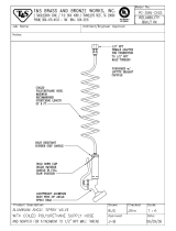
Installation on a Ram
(Carbon Steel and Aluminum Plates)
Installing the Wiper Plate on a Ram
(Model 222812 shown; large diameter of
spacer facing down)
06540
A
Fig. 1
1
A
B
C
3
F
H
G
To use Model 222812 and 235516, Plates with tapered
pails, the spacer (19) must be removed. See page 6,
and Figs. 2–4.
19 1
0248A
Fig. 2
19
D
E
0249A
Fig. 3
D
E
19
0251A
Fig. 4
19
D
E

8 308049
Installation on a Cart
(Carbon Steel and Aluminum Plates)
Installation
Reference letters and numbers in the text refer to Figs.
5–8 and the Parts Drawings on pages 14–15.
WARNING
MOVING PARTS HAZARD
Moving parts can pinch or amputate your
fingers. When the pump is operating and
when raising or lowering the ram, keep
your fingers and hands away from the priming
piston and the lip of the pail.
WARNING
To reduce the risk of serious injury whenever you
are instructed to relieve pressure, always follow the
Pressure Relief Procedure on page 5.
1. Relieve the pressure.
2. Install the wiper plate (A) onto the pump intake (B),
with the wiper plate vent handle (C) facing the front
of the cart. Secure by tightening the setscrew (3).
See Fig. 5.
3. The wiper plate is supplied for use with 19 liter (5
gallon) straight sided pails on a ram. It must be
modified for use with the pneumatic elevator cart.
See steps a and b, following.
a. To use the wiper plate with straight sided
pails, the large spacer (19) must be inverted.
Working from the bottom, use a screwdriver to
pry the spacer loose. Work it upward so it is
completely above the flange (D) of the wiper
plate. See Fig. 6. Next, by hand, angle the
spacer and work it off the plate, pulling it down
over the flange and bottom wipers (E). See
Fig. 7. Turn the spacer so the large diameter
is facing up. Work the spacer up over the
wiper plate by hand, so it is completely above
the flange (D) of the wiper plate. Working from
the top, use a screwdriver to position the
spacer between the flange (D) and the wipers
(E). See Fig. 8.
b. To use the wiper plate with tapered pails,
the large spacer (19) must be removed. Work-
ing from the bottom, use a screwdriver to pry
the spacer loose. Work it upward so it is com-
pletely above the flange (D) of the wiper plate.
See Fig. 6. Next, by hand, angle the spacer
and work it off the plate, pulling it down over
the flange and bottom wipers (E). See Fig. 7.
Save the spacer, as it is required for other
applications.
4. Install Cart Accessory Kit 224376. See 308087 for
details.
5. Refer to the separate cart and pump manuals for
set-up and operating instructions.
Maintenance
If the wiper plate does not come out of the pail easily
when the pump is being raised, the air assist tube (F),
fitting (H), or check valve (21) may be plugged. This
prevents air from reaching the underside of the plate to
assist in raising it from the pail.
WARNING
To reduce the risk of serious injury whenever you
are instructed to relieve pressure, always follow the
Pressure Relief Procedure on page 5.
Relieve the pressure. Refer to the Parts Drawings on
pages 14–15 and disassemble the air assist check
valve as shown. Clear the tube (F) and the port in the
wiper plate. Clean all parts of the check valve assem-
bly, and reassemble.

308049 9
Installation on a Cart
(Carbon Steel and Aluminum Plates)
Installing the Wiper Plate on a
Pneumatic Elevator Cart
(Model 222812 shown;
large diameter of spacer facing up)
0252D
Fig. 5
1
2
A
C
3B
H
Part of Kit 224376 (See 308087).
To use Model 222812 and 235516 Plates with tapered
pails, the spacer (19) must be removed. See page 8,
and Figs. 6–8.
19
2
1
F
0248A
Fig. 6
19
D
E
0249A
Fig. 7
D
E
19
Fig. 8
19
0251A
D
E

10 308049
Installation on a Ram
(Stainless Steel Plates)
Installation
Reference letters and numbers in the text refer to Figs.
9–12 and the Parts Drawing on page 16.
WARNING
MOVING PARTS HAZARD
Moving parts can pinch or amputate your
fingers. When the pump is operating and
when raising or lowering the ram, keep
your fingers and hands away from the priming
piston and lip of the pail.
WARNING
To reduce the risk of serious injury whenever you
are instructed to relieve pressure, always follow the
Pressure Relief Procedure on page 5.
1. Relieve the pressure.
2. Install the wiper plate (A) onto the pump intake (B),
with the wiper plate vent handle (C) facing the left
of the ram. Secure by tightening the setscrews
(17). See Fig. 9.
3. The wiper plate is supplied for use with 19 liter (5
gallon) straight sided pails, but it can be easily
modified for use with tapered pails. See steps a
and b
a. To use the wiper plate with tapered pails,
the large spacer (8) must be removed. Work-
ing from the bottom, use a screwdriver to pry
the spacer loose. Work it upward so it is com-
pletely above the flange (D) of the wiper plate.
See Fig. 10. Next, by hand, angle the spacer
and work it off the plate, pulling it down over
the flange and bottom wipers (E). See Fig. 11.
Save the spacer, as it is required for other
applications.
b. To reinstall the spacer for use with a
straight sided pail, first make sure the large
diameter of the spacer (8) is facing down.
Work the spacer up over the wiper plate by
hand, so it is completely above the flange (D)
of the wiper plate. See Fig. 11. Then, working
from the top, use a screwdriver to position the
spacer between the flange (D) and the wipers
(E). See Fig. 12.
4. Connect a 965 mm (38 in.), 6.3 mm (1/4 in.) OD
tube (F) from the ram’s air assist valve (G) to the
elbow (H) on the wiper plate.
5. Refer to the separate ram and pump manuals for
set-up and operating instructions.
Operating the Air Assist Valve Handle
The ram’s air assist valve (G) directs air under the
wiper plate, making it easier to pull the plate out of the
pail. For the air assist valve to function, you must open
a passage for the air with the valve handle (J). Practice
using the handle a few times, until you are familiar with
its use.
WARNING
To reduce the risk of serious injury whenever you
are instructed to relieve pressure, always follow the
Pressure Relief Procedure on page 5.
1. Stop the pump. Relieve the pressure.
2. To open a passage for air to get under the plate,
rotate the handle (J) 45_ clockwise and pull it
upward (it should travel about 13 mm [1/2 in.] up
and down).
3. Turn the ram director valve to UP. Press the air
assist valve (G), and hold it in until the plate clears
the top of the pail.
4. To close the air passage, push the handle (J) down
and rotate it 45_ counterclockwise to lock.
Maintenance
If the wiper plate does not come out of the pail easily
when the pump is being raised, the air assist tube (F),
elbow (H), or valve (J) may be plugged. A plugged
valve prevents air from reaching the underside of the
plate to assist in raising it from the pail.
WARNING
To reduce the risk of serious injury whenever you
are instructed to relieve pressure, always follow the
Pressure Relief Procedure on page 5.
Relieve the pressure. Refer to the Parts Drawing on
page 16 and disassemble the air assist valve (J) as
shown. Clear the hose (F) and the elbow (H) in the
wiper plate. Clean all parts of the valve, and reas-
semble.

308049 11
Installation on a Ram
(Stainless Steel Plates)
Installing the Wiper Plate on a Ram
(large diameter of spacer facing down)
06754C
Fig. 9
1
A
B
C
F
H
G
17
J
To use Model 222909 Plate with a tapered pail, the spacer (8)
must be removed. See page 10, and Figs. 10–12.
8
F
1
Fig. 10
D
E
01116
8
Fig. 11
01117
D
E
8
Fig. 12
01118
D
E
8

12 308049
Installation on a Cart
(Stainless Steel Plates)
Installation
Reference letters and numbers in the text refer to Figs.
13–16 and the Parts Drawing on page 16.
WARNING
MOVING PARTS HAZARD
Moving parts can pinch or amputate your
fingers. When the pump is operating and
when raising or lowering the ram, keep
your fingers and hands away from the priming
piston and the lip of the fluid container.
WARNING
To reduce the risk of serious injury whenever you
are instructed to relieve pressure, always follow the
Pressure Relief Procedure on page 5.
1. Relieve the pressure.
2. Install the wiper plate (A) onto the pump intake (B),
with the wiper plate vent handle (C) facing the left
of the cart. Secure by tightening the setscrews
(17). See Fig. 13.
3. The wiper plate is supplied for use with 19 liter (5
gallon) straight sided pails on a ram. It must be
modified for use with the pneumatic elevator cart.
See steps a and b following.
a. To use the wiper plate with straight sided
pails, the large spacer (8) must be inverted.
Working from the bottom, use a screwdriver to
pry the spacer loose. Work it upward so it is
completely above the flange (D) of the wiper
plate. See Fig. 14. Next, by hand, angle the
spacer and work it off the plate, pulling it down
over the flange and bottom wipers (E). See
Fig. 15. Turn the spacer so the large diameter
is facing up. Work the spacer up over the
wiper plate by hand, so it is completely above
the flange (D) of the wiper plate. Working from
the top, use a screwdriver to position the
spacer between the flange (D) and the wipers
(E). See Fig. 16.
b. To use the wiper plate with tapered pails,
the large spacer (8) must be removed. Work-
ing from the bottom, use a screwdriver to pry
the spacer loose. Work it upward so it is com-
pletely above the flange (D) of the wiper plate.
See Fig. 14. Next, by hand, angle the spacer
and work it off the plate, pulling it down over
the flange and bottom wipers (E). See Fig. 15.
Save the spacer, as it is required for other
applications.
4. Install Cart Accessory Kit 224376. See 308199 for
details.
5. Refer to the separate cart and pump manuals for
set-up and operating instructions.
Operating the Air Assist Valve Handle
The cart’s air assist toggle valve (G) directs air under
the wiper plate, making it easier to pull the plate out of
the pail. Refer to manual 308199 for instructions on
changing pails using the air assist valve.
For the air assist valve to function, you must open a
passage for the air with the valve handle (J). Practice
using the handle a few times, until you are familiar with
its use.
WARNING
To reduce the risk of serious injury whenever you
are instructed to relieve pressure, always follow the
Pressure Relief Procedure on page 5.
1. Relieve the pressure.
2. To open a passage for air to get under the plate,
rotate the handle (J) 45_ clockwise and pull it
upward (it should travel about 13 mm [1/2 in.] up
and down).
3. To close the air passage, push the handle (J) down
and rotate it 45_ counterclockwise to lock.
Maintenance
If the wiper plate does not come out of the pail easily
when the pump is being raised, the air assist tube (F),
elbow (H), or valve (J) may be plugged. A plugged
valve prevents air from reaching the underside of the
plate to assist in raising it from the pail.
WARNING
To reduce the risk of serious injury whenever you
are instructed to relieve pressure, always follow the
Pressure Relief Procedure on page 5.
Relieve the pressure. Refer to the Parts Drawing on
page 16 and disassemble the air assist valve (J) as
shown. Clear the hose (F) and the elbow (H) in the
wiper plate. Clean all parts of the valve, and reas-
semble.

308049 13
Installation on a Cart
(Stainless Steel Plates)
Installing the Wiper Plate on a
Pneumatic Elevator Cart
(large diameter of spacer facing up)
Fig. 13
1
2
01096
A
B
C
H
G
Part of Kit 224376; see 308199.
17
J
To use Model 222909 Plate with a tapered pail, the spacer (8)
must be removed. See page 12, and Figs. 14–16.
F
8
1
2
Fig. 14
D
E
01116
8
Fig. 15
01117
D
E
8
Fig. 16
D
E
01118
8

0254B
1
2
4
3
21
6
16
14
9
15
5
19
12
13
0254D
14 308049
Parts
Model C50260, Series B
Model 222812, Series B
Carbon Steel Wiper Plate
with Buna-N Wiper
and UHMWPE Backup
Ref. Part
No. No. Description Qty
Ref. Part
No. No. Description Qty
1 101831 PIN, spring, straight 1
2 177542 HANDLE 1
3 100421 SETSCREW, socket hd, cup point;
5/16–18 x 3/8 in. (9.5 mm) long 2
4 166560 STEM, probe 1
5n 184420 WIPER; synthetic rubber 1
6 109469 SCREW, machine, flat-hd;
zinc-plated carbon steel;
1/4–20 x 1 in. (25 mm) long 8
9 184419 CLAMP, retaining
zinc-plated carbon steel 1
12 222764 PLATE, wiper;
zinc-plated carbon steel 1
13 109458 O-RING; fluoroelastomer 1
14 102040 NUT, hex, self-locking;
with nylon insert; 1/4–20 unc–3b 8
15n 184421 WIPER; polyethylene
(Model 222812 only) 1
16 184418 CLAMP, retaining;
zinc-plated carbon steel 1
19 276049 SPACER; polyurethane 1
21 114317 VALVE, check, air assist 1
n Keep these spare parts on hand to reduce down time.

01456A
1
2
4
3
6
16
14
9
15
5
19
12
20
21
13
308049 15
Parts
Model 235516, Series B
Carbon Steel Wiper Plate
with PTFE-coated Wiper
and UHMWPE Backup
Ref. Part
No. No. Description Qty
Ref. Part
No. No. Description Qty
1 101831 PIN, spring, straight 1
2 177542 HANDLE 1
3 100421 SETSCREW, socket hd, cup point;
5/16–18 x 3/8 in. (9.5 mm) long 1
4 166560 STEM, probe 1
5n 184552 WIPER; nitrile/PTFE 1
6 109469 SCREW, machine, flat-hd;
zinc-plated carbon steel;
1/4–20 x 1 in. (25 mm) long 8
9 184419 CLAMP, retaining
zinc-plated carbon steel 1
12 222764 PLATE, wiper;
zinc-plated carbon steel 1
13 109458 O-RING; fluoroelastomer 1
14 102040 NUT, hex, self-locking;
with nylon insert; 1/4–20 unc–3b 8
15n 184421 WIPER; polyethylene 1
16 184418 CLAMP, retaining;
zinc-plated carbon steel 1
19 276049 SPACER; polyurethane 1
20n 184551 WIPER; polyethylene 1
21 114317 VALVE, check, air assist 1
n Keep these spare parts on hand to reduce down time.

1
2
4
13
6
16
11
14
7
8
10
9
15
5
17
12
01119
20
3
19
19
14 (Ref)
K
L
01213
14 13
19
15
19
K
1
L
11
12
16
Assembled Detail of Air Assist Check Valve
1
2
PTFE side faces down, toward fluid.
Located inside assembly of items 1 and 5.
2
1
16 308049
Parts
Model 222909, Series A
Stainless Steel Wiper Plate
with PTFE-coated Wiper
and UHMWPE Backup
Valve Assembly Procedure
(see Detail below)
1. Assemble all wipers and the clamp (9) to the plate
(5) as shown at left, before assembling the valve.
2. Insert the seal (19) in the hole (K) of the collar (1).
Align the hole and the flat of the guide (15) with the
hole (L) in the collar, and install the guide. Screw
the elbow (11) into the hole (L) until snug. Do not
overtighten. The guide (15) should be held from
rotating by the elbow (11) but should not be
clamped firmly in place.
3. Slide the nut (13) and seal (19) onto the stem (14).
Press the pin (12) into the hole in the stem (14)
until the pin bottoms out.
4. Insert the stem (14) into the hole (K) so the pin
(12) travels in the slot of the guide (15). Push the
seal (19) down into the hole (K) and tighten the nut
(13) snugly – do not overtighten. (Stem (14)
should not rotate more than 90_).
5. Operate the valve a few times to ensure proper
assembly.

308049 17
Parts
Model 222909, Series A
Stainless Steel Wiper Plate
with PTFE-coated Wiper
and UHMWPE Backup
Ref. Part
No. No. Description Qty
Ref. Part
No. No. Description Qty
1 184471 COLLAR, wiper plate; sst 1
2 184481 STEM, probe; sst 1
3 109482 O-RING; PTFE 1
4 103972 SCREW, drive, u-type;
0.188 in. (5 mm) long 3
5 222915 PLATE, wiper; sst 1
6n 184421 WIPER; polyethylene 1
7n 184552 WIPER; nitrile/PTFE 1
8 276049 SPACER; polyurethane 1
9 184477 CLAMP, retaining; sst 1
10 109478 NUT, lock, hex; w/nylon insert;
1/4–20 unc–2b 8
11 109506 ELBOW, tube fitting, 90_;
1/8 npt(m) x 1/4 in. (6.3 mm) tube size 1
12 109479 PIN, spring, straight;
3/32 in. size x 3/8 in. (9.5 mm) long 1
13 184482 NUT, retainer; sst 1
14 184479 STEM, valve; sst 1
15n 184531 GUIDE, valve; sst 1
16 109458 O-RING; fluoroelastomer 1
17 109477 SCREW, cap, hex head;
5/16–18 unc–2a; 1/2 in. (13 mm) long 2
19n 184530 SEAL, valve; PTFE 2
20n 184551 WIPER; polyethylene 1
21 114317 VALVE, check, air assist 1
n Keep these spare parts on hand to reduce down time.

1
2
4
3
21
6
16
14
9
15
5
19
12
13
23
24
25
0254D
18 308049
Parts
Model 241081, Series A
Carbon Steel Wiper Plate
with Buna-N Wiper
and UHMWPE Backup
Ref. Part
No. No. Description Qty
Ref. Part
No. No. Description Qty
1 101831 PIN, spring, straight 1
2 177542 HANDLE 1
3 100421 SETSCREW, socket hd, cup point;
5/16–18 x 3/8 in. (9.5 mm) long 2
4 166560 STEM, probe 1
5n 194146 WIPER; synthetic rubber 1
6 109469 SCREW, machine, flat-hd;
zinc-plated carbon steel;
1/4–20 x 1 in. (25 mm) long 8
9 194151 CLAMP, retaining
zinc-plated carbon steel 1
12 241080 PLATE, wiper;
zinc-plated carbon steel 1
13 109458 O-RING; fluoroelastomer 1
14 102040 NUT, hex, self-locking;
with nylon insert; 1/4–20 unc–3b 8
15n 194147 WIPER; polyethylene 1
16 194149 CLAMP, retaining;
zinc-plated carbon steel 1
19 276049 SPACER; polyurethane 1
21 C20467 VALVE, check, air assist 1
23 111842 FITTING, elbow, pipe 45_ 1
24 155665 UNION, adapter 1
25 208391 VALVE, ball 1
n Keep these spare parts on hand to reduce down time.

0254B
1
2
4
3
6
16
14
9
15
5
17
12
13
18
19
20
21
0254D
308049 19
Parts
Model 918409, Series B
Carbon Steel Wiper Plate
with Buna-N Wiper
and UHMWPE Backup
Ref. Part
No. No. Description Qty
Ref. Part
No. No. Description Qty
1 101831 PIN, spring, straight 1
2 177542 HANDLE 1
3 100421 SETSCREW, socket hd, cup point;
5/16–18 x 3/8 in. (9.5 mm) long 2
4 166560 STEM, probe 1
5n 184420 WIPER; synthetic rubber 1
6 109469 SCREW, machine, flat-hd;
zinc-plated carbon steel;
1/4–20 x 1 in. (25 mm) long 8
9 184419 CLAMP, retaining
zinc-plated carbon steel 1
12 222764 PLATE, wiper;
zinc-plated carbon steel 1
13 109458 O-RING; fluoroelastomer 1
14 102040 NUT, hex, self-locking;
with nylon insert; 1/4–20 unc–3b 8
15n 184421 WIPER; polyethylene 1
16 184418 CLAMP, retaining;
zinc-plated carbon steel 1
17 276049 SPACER; polyurethane 1
18n C20467 FITTING, nipple, reducer 1
19 111842 FITTING, elbow, pipe 45_ 1
20 208391 VALVE, ball 1
21 155665 UNION, adapter 1
n Keep these spare parts on hand to reduce down time.

20 308049
Notes
/