AfterBurner 420 Installation & Operation Instructions
- Category
- Network antennas
- Type
- Installation & Operation Instructions

-AFTERBURNER
ORDER NO.
420
BASE STATION 115V AC
BI-LATERAL LINEAR AMPLIFIER
CoPY
INSTALLATION
&
OPERATION INSTRUCTIONS
AFTERBURNER
RuraI Route 3
Lincoln. Nebraska 68505
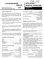
The Bi-Lateral Amplifier is a precision built, compact amplifier of
advanced design. It uti Iizes an integrated circu it, two tubes, two
transistors and three diodes and a grounded grid, tuned plate
circuit for amplification of AM, FM, CW, and SSB signals in the
25· 54MHz range.
A special feature of the Ampl ifier is the automatic antenna
change over relay which operates without special external
connections making it perfect for operation with low power
transceivers not having external amplifier control circuits.
Another feature is that this unit amplifies the received signal)uti-
lizing an integrated circuit amplifier.
Variable plate tune and load capacitors offer impedance matching
for maximum output to varying antenna loads in the 40-70 ohm
range.
~Ie Bi-Lateral Ampl ifier has been designed and constructed to
~uppress radiation that may cause television interference. TVI
problem has been given full consideration in design and layout of
the chassis.
There are, however, some types of TV! that cannot be prevented
within the amplifier. This is particularly true in weak signal areas.
In such cases, a good commercial low pass filter is recommended.
Height 4 1/8"
Width 7 1/8"
Depth 103/8"
Net Weight 11 Lbs.
Shipping Weight 12 Lbs.
Construction Lightweight aluminum chassis
with rugged steel case
Power Requirement 115 V AC
3Amp
Frequency Range 25-54 MHz
Types of Emmission ., AM, FM, CW, SSB, DSB
Power Output (Slightly less at 50 MHz) 220 Watts PEP, SSB,
or DSB
100 Watts (With 3.5 watts drive)
~ Amplification of Received Signal 20 db
Drive Requirement to Trigger Antenna Relay 1 Watt
Max Drive (unmodulated carrier) 15 Watts
Odd Order Distortion Products 30 db below peak output
Harmonic Suppression 2nd Harmonic at least 35 db
below peak output
Input Impedance (unbalanced) 50 Ohms
nominal, less than 2: 1 VSWR 25-54 MHz
Output Impedance(unbalanced) 50 Ohms
nominal, Adjustable 40-70 ohms, nonreactive
Antenna Switching Automatic provided by RF
sensing network
Tube and Diode Complement 2 Tubes
2 Transistors, 3 Diodes
1 Integrated Circuit
Cable Connector Data Input and Output
require MIL PL-259
() Carefully remove the amplifier from the packing carton.
Examine it closely for signs of shipping damage. Remove the four
screws holding the top cabinet and remove all hold-down tape
and packing materials. Check to insure tubes are seated in the
sockets. Install the plate caps on the tubes and the fuse in the
holder. Inspect for any signs of internal damage.
Do not attempt to operate your amplifier until you have read
the manual and properly installed the unit.
() The location is not critical but consideration must be given to
adequate ventilation.
() IMPORTANT: Allow at least 4" of clearance on all sides of
the cabinet for good air circulation.
() The primary power connection on the amplifier is a standard
115 V AC line plug.
() The fuse holder is provided on the rear panel with a 3 amp, 3
AG fuse. Do not use a larger capacity fuse or amplifier,
transformer, and power supply will not be protected.
() The unit should be operated with a good ground. Water pipes
and other house fixtures are not recommended.
() The Bi-Lateral Amplifier will work with the common antenna
systems designed for the 25-54 MHz range provided the antenna
has a resistive input impedance between 40-70 ohms. The SWR
should be kept to a minimum of 2:1 or less.
() The output connector provided is an SO-239. For connection
of your antenna, you will need a PL-259 plug.
ON-OFF Switch Controls 120V AC power to amplifier.
AM-FM
&
SSB Switch Adjust delay constant of automatic
antenna relay.
XMT-Stanby Switch Activates the automatic antenna
relay circuit,
also supplies power to the receive amplifier circuit.
Receiver Amplifier ON-OFF Switch .... Activates the integrated
circuit receive amplifier.
NOTE: Receive amplifier will only operate when
the XMT-Standby switch is in the XMT position.

RED Indicator Light Visual indication of
applied115 V AC power.
Output Meter Visual indication of
relative RF power output.
Tune Knob Adjusts resonant frequency
of amplifier.
Load Knob Adjusts coupling of
output circu it to. antenna.
Th is amplifier must be used with a transm itter or transceiver
capable of at least one watt output, in the 25-54 MHz range.
First place the fu nction switch in the AM-FM position. Set the
tune control in accordance with the warning on page 3 of the
manual. The load control should be positioned so that the
capacitor is fully meshed, (dot on knob will then point to the
word "load" on the front panel).
Now push the ON-Off switch to ON. The red visual indicator light
will light.
After warm-up, push the XMT-Standby to XMT. This will
energize the automatic antenna relay control circuitry, and
provide power for the integrated circuit receive amplifier.
Apply drive power by keying the exciter (transceiver)
microphone and quickly adjust the tune control for maximum
deflection on the output meter. Remove drive power after
adjustment.
Do not apply drive power for more thEm five seconds without
adjusting the tune control or damage to the tubes can result.
Reapply drive power and advance (clockwise) the load control,
note the increase in deflection of the output meter. Adjust the
load control for maximum output. Remove drive power.
Readjustment of the tuning and loading controls several
times will produce maximum output.
To provide for the extra power contained in the AM signal
modulation it is necessaryto "overcouple" the output circuit.
This is necessaryto insure an undistorted output with a minimum
of adjacent channel "bleeding" (spatter).
Reapply drive power and advance the load control until the
output meter drops perceptably, (about 15 per cent more
rotation). Readjust the tune control for maximum output. The
output circu it is now" overcoupled".
If a relative power output indicator is available (SWR bridge on
forward, etc.) the output signal can be quickly checked to insure
upward modulation. If the meter does not "flick" upward on
voice peaks, the load control is improperly set (or the exciter is
not capable of 100 per cent modulation or may have "downward
modulation"). Also seen on output meter.
Automatic antenna change over and amplifier operation is
provided for by a special transistorized input sensing circuit.
Should you desire to hold the amplifier in a "ready" condition,
but not use it until needed,simply place the XMT-Standby in the
standby position. The sensing circuit will be disabled and the
antenna connected to the exciter (transceiver) at all times.
IMPORTANT
With the XMT-Standby switch in the standby POSition, the
REC AMP switch should be in the OFF position. This will
prevent the receive amplifier loading the transceiver oytput.
The amplifier is tuned for FM service in a manner identical
tp
AM
except the load and tune controls are setfor maximum outp~t.
Placethe function switch in the SSB position. This will connect a
delay circuit to the automatic relay control and extend the
"drop-out" approximately one second. This will prevent relay
"chattering" and erratic operation. ~
If the exciter (transceiver) is capable of carri?r output equal to
the peak power of the voice SSBor DSB signal, simply adjust the
tune and load controls for maximum deflection of the qutput
meter while applying carrier.
If the exciter (transceiver) cannot supply a carrier equal to the
peak power of the voice SSB or DSB signal then the tune and
load controls must be set for maximum output while modulating.
In this case,a modulation envelope indicator (monitor scope) is
the most reliable method for adjustment of the amplifier.
Place the function switch in the SSB position, apply drive power,
and adjust the tune and load controls for maximum output.
The delay circuit for SSB prevents "drop-out" of the auto'matic
antenna relay between characters.
For operation on the six meter amateur band It
IS
necessaryto
short out four turns from the left hand side asviewed from the
front panel of the Pi-network output coil, L1. The 100pf silver
mica capacitor acrossC17 load capacitor, must be removed.~
remove capacitor C7, 50 pf disc ceramic located acrossthe I
socket of the rear panel.

REMOVE FOR
b
METER
AMATEUR BAND
OPERATION
IOOpf CAPACITOR
ACCROSS C-17
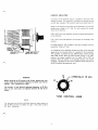
Before applying any RF power to the Linear, pretune the tune
control knob to the desired frequency at which you wish to
operate. See illustration at right.
For example, if your desired operating frequency is 28 MHz
then set the tune knob at midpoint between 26 and 30 as
shown.
For operation on the
50
to
54
MHz band set tune control to
the
30
MHz position as shown at right. Then refer to
50
to
54 MHz Operation.
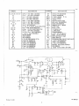
A portion of the incoming circuit is coupled to the base of Q1
sensing transistor. This causes Q1 to conduct and change. the bias
on Q2, relay transistor. Q2 conducts heavily and closes relay K 1.
Relay K 1 connects the input signal to the cathodes of V1 and V2,
applies plate voltage to V 1 and V2, and connects the output
circu it to the antenna.
C18 is the Pi-net tune capacitor and sets the operating frequency
of the ampl ifier.
C17 is the Pi-net load capacitor and controls the coupling to the
antenna.
For SSB operation, C22 is added to the relay transistor circu it to
extned the "drop out" time.
An integrated circuit amplifier increases the level of the incoming'
signals from the antenna before it is applied to the transceiver.
This amplifier is powered by the XMT-Standby switch and the
REC AMP switch. With the XMT-Standby switch in the XMT
position the receive amplifier can be switch ON or OFF as
requ ired. With the switch in the standby position, the receive
amplifier is disabled and the receive amplifier switch should be in
the OFF position (see important note).

2200.&L1/4W RESISTOR
10Jl1W RESISTOR
27 MHZ CHOKE
23
144
47p.H
CHOKE
CHOKE
23
144
6JU6 VACUUM TUBE
MPS 6516 TRANSISTOR
2N696 TRANSISTOR
OHMITE ~-28 CHOKE
TANK COIL
.56..M.h
COIL
l4V BULB #53
il AMP FUSE
TRANSFORMER
3 PDT 12V DC RELAY
SPDT 12V DC RELAY
SPST SWITCH 10 AMP
DPST SWITCH
INTERGRATED CIRCUIT MC1550/G
1. 2K.n 1/4W RESISTOR
10K.a.1/2W RESISTOR
4. 7Kn.1/2W RESISTOR
METER, RELA TIVE POWER
1N34 DIODE
.01mfd CAPACITOR 1KV DISC
2200 pf 1KV DISC CERAMIC
150 pI 1KV DISC CERAMIC
56
I)f
1KV DISC CERAMIC
50 pi' 1KV DISC CERAMIC
20 pf 1KV DISC CERAMIC
6800
1)[
1KV DISC CERAMIC
il300
~f
3KV DISC CERAMIC
1000 pf 1KV DISC CERAMIC
100 pf SILVER MICA
10 rnf 25-35 WVDC ELECTROLYTIC
40 mf 450V ELECTRO~ YTIC
500 mf 15V DC ELECTROLYTIC
100 pf 1KV DISC CERAMIC
10. 5-il13. 9 pf AIR VARIABLE
3.2-50 pf AIR VARIABLE
1N5054 DIODE
1N645 DIODE
1N270 DIODE
6.2V ZE NER DIODE 1N753
270K.a..1W RESISTOR
510.t1.1/4W RESISTOR
1200A1/4W RESISTOR
330A1/2W RESISTOR
270.Jl1/4W RESISTOR
33.n.1/4W RESISTOR
R8
R9
RFC1
RFC2
RFC3
V1,2
Q1
Q2
RFC4
L1
L2,3
N1
F1
T1
K1
K2
Sl,2,3
S4
1 C 1
RIO
Rll
B12
M1
D8
C25
C2,29,30,828,20
C1
C9
C7
C14
C12,
24,15,16,23
C19
C4,5,
13
C27
C21
Cll,10
C22,26
C3
C17
C18
D1,2
D3
D5,6
D7
R1,2
R3
R4
R5
R6
R7,13
~C27
TI
~Sl
9~
F
.2
lell
-
 1
1
-
 2
2
-
 3
3
-
 4
4


AfterBurner 420 Installation & Operation Instructions
- Category
- Network antennas
- Type
- Installation & Operation Instructions
Ask a question and I''ll find the answer in the document
Finding information in a document is now easier with AI
Other documents
-
 AMERITRON AL-811HDY User manual
-
 AMERITRON AL-572 User manual
-
 AMERITRON ALS-600Y User manual
-
 AMERITRON ALS-600SPS User manual
-
 AMERITRON Al-800H User manual
-
AMERITRON AL-800XCE User manual
-
AMERITRON AL-811HX Specification
-
 AMERITRON AL-82 User manual
-
 AMERITRON AL-80BX User manual
-
Swann 350 Operation And Maintenance


