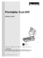
Makita 2414DB is a portable cut-off tool designed for cutting various materials such as metal, plastic, and wood. It features a powerful motor that delivers 3,800 RPM, enabling it to handle demanding cutting tasks. The tool comes equipped with a 14-inch cut-off wheel, providing a large cutting capacity. Makita 2414DB also incorporates several safety features, including a wheel guard to protect the user from flying sparks and debris, as well as a lock-off button to prevent accidental activation.
Makita 2414DB is a portable cut-off tool designed for cutting various materials such as metal, plastic, and wood. It features a powerful motor that delivers 3,800 RPM, enabling it to handle demanding cutting tasks. The tool comes equipped with a 14-inch cut-off wheel, providing a large cutting capacity. Makita 2414DB also incorporates several safety features, including a wheel guard to protect the user from flying sparks and debris, as well as a lock-off button to prevent accidental activation.


-
 1
1
-
 2
2
-
 3
3
-
 4
4
-
 5
5
-
 6
6
-
 7
7
-
 8
8
-
 9
9
-
 10
10
-
 11
11
-
 12
12
-
 13
13
-
 14
14
-
 15
15
-
 16
16


Makita 2414DB is a portable cut-off tool designed for cutting various materials such as metal, plastic, and wood. It features a powerful motor that delivers 3,800 RPM, enabling it to handle demanding cutting tasks. The tool comes equipped with a 14-inch cut-off wheel, providing a large cutting capacity. Makita 2414DB also incorporates several safety features, including a wheel guard to protect the user from flying sparks and debris, as well as a lock-off button to prevent accidental activation.
Ask a question and I''ll find the answer in the document
Finding information in a document is now easier with AI