American Standard 2590.900.295 Installation guide

Category
Sanitary ware
Type
Installation guide

This manual is also suitable for

American Standard 2590.900.295 is a studio deck mount bath filler with a spout assembly, valve assembly, and handshower installation. It features adjustable handles that rotate 90 degrees, a 12-inch maximum reach from the spout center, and 3/4-inch NPT male valve inlets. The included spray escutcheon and rubber ring ensure proper seating and prevent leaks. The handshower hose connects to the outlet nipple at the bottom of the tee for added functionality.

American Standard 2590.900.295 is a studio deck mount bath filler with a spout assembly, valve assembly, and handshower installation. It features adjustable handles that rotate 90 degrees, a 12-inch maximum reach from the spout center, and 3/4-inch NPT male valve inlets. The included spray escutcheon and rubber ring ensure proper seating and prevent leaks. The handshower hose connects to the outlet nipple at the bottom of the tee for added functionality.

DECK MOUNT BATH FILLER
STUDIO
Certified to comply with ANSI A112.18.1M
Recommended Tools
*Supplied with Fitting
*Hex key (4mm)
3/8" Hex key
Turn off hot and cold water
supplies before beginning.
CAUTION
1
2
Insert SPOUT SHANK (3) through center hole of MOUNTING LEDGE.
Make sure that the RUBBER RING (1) is properly seated in RECESS
of ESCUTCHEON RING (2).
Assemble RUBBER WASHER (4) and BRASS WASHER (5) onto
SHANK (3). From underside of ledge secure SPOUT (7) into position
with LOCKNUT (6).
SPOUT ASSEMBLY
PREPARE TUBE AND TEE ASSEMBLY
4
2
3
1
3
4
Prepare TUBE and TEE ASSEMBLY (1) to fit center to center
VALVE (2) location (between 6-1/2" and 12"). If necessary,
cut and/or bend TUBING carefully. Make sure tube bend is
close to the TEE (1) so that it will not effect the compression
joint at the VALVE CONNECTION.
Remove COUPLING NUT (3) and FERRULE (4) from each
VALVE (2) and slide onto TUBING (5).
5
2
Flat Blade Screwdriver
Adjustable Wrench
Channel Locks
VALVE inlet is
3/4-inch NPT male.
NOTE
MOUNTING
SURFACE
3-1/4" D.
(82mm) D.
2"
(52mm) D.
ROUGHING-IN DIMENSIONS
MOUNTING
SURFACE
7-1/4"
(184mm)
4"
(103mm)
5-1/4"
(133mm)
3-1/8"
(80mm)
6-1/2" to 12"
(165mm to 305mm)
Installation
Instructions
2590.90X
2590.901
2590.900
1-1/2 MAX.
(38mm) MAX.
1-3/16" MAX.
(30mm) MAX.
1-3/16 D.
(30mm) D.
3'
(76mm)
(H)
(C)
1-1/8 D.
12 MAX.
(305mm)
2-1/16" D.
(52mm) D.
1-1/16 D.
(27mm) D.
3/4-14 MALE
N.P.T. INLETS
Tubing Cutter
RECESS
3
7
1
4
6
2
5
MOUNTING
SURFACE
6-1/2" to 12"
(165mm to 305mm)
Install RUBBER RING (1) into ESCUTCHEON RING (2) and
place over mounting hole.
M968627 Rev.1.2
Thank you for selecting American-Standard...
the benchmark of fine quality for over 100 years.
To ensure that your installation proceeds smoothly--
please read these instructions carefully before you begin.
8-15/16"
(227mm)
9
2
4
5/16'' MIN.
MOUNTING
SURFACE
10
11
11
10
2
1
1
3
Push TUBING (3) ends into VALVE (4) side outlets. Insert VALVES (4)
into mounting holes from underside of ledge.
Press TEE (5) onto SPOUT SHANK (6) making certain that the O-RING (7) is
properly seated on SHANK (6). Push COUPLING (8) into TEE (5) and attach to
SPOUT SHANK (6) and tighten using a 10mm (3/8'') hex wrench. Tighten
COUPLING (8) using a 10mm (3/8") Hex wrench. (FOR 2590.901). Use
COUPLING (8a) for fitting less spray (FOR 2590.900).
Install LOCKNUTS (1) and RUBBER WASHERS (2) onto valve shanks.
Place RUBBER RING (10) into ESCUTCHEON ADAPTERS (9) and thread onto
valves until snug against internal stop.
Tighten LOCKNUT (1) with channel lock to secure VALVE (4) position.
Slide FERRULE (12) and COUPLING NUT (13) to outlet of VALVE (4) and tighten
COUPLING NUT (13) firmly.
Connect HOT water supply to inlet of left VALVE and COLD water supply to inlet of
right VALVE using appropriate connector.
VALVE ASSEMBLY
HOT
COLD
12
4
13
7
6
8
8a
5
13
12
3
4
MOUNTING
SURFACE
Thread of VALVE BODY (4) should extend at least 5/16 inch above MOUNTING
SURFACE (11). If necessary, adjust LOCKNUT (1).
10
9
9
M968627 Rev.1.2
To change direction of handle rotation,
proceed as follows:
Turn valve to OFF position.
Thread counter-clock wise HANDLE BASE (1) to remove
HANDLE ASSEMBLY (2) from ESCUTCHEON BASE (3).
Use a flat blade screw driver to remove SPRING CLIP (4).
Lift STOP WASHER (5), turn 90˚ and replace.
Replace SPRING CLIP (4).
Reinstall HANDLE ASSEMBLY (2).
If spout drips, operate handles several times from OFF to ON
position. Do not force - handles turn only 90˚.
SERVICE
90˚
VALVE
1
5
3
4
2
4
5
INSTALL HANDLES
1
2
4
5
3
TOP
Figure "A"
SPLINE END DOWN
Push ADAPTER (1) on VALVE STEM (2), so that the hole of the
ADAPTER (1) without a spline is facing up. See figure "A". Tighten
STEM SCREW (3) to secure ADAPTER (1).
Find correct position of LEVER HANDLE ASSEMBLY (4) by adjusting
male teeth on ADAPTER (1) to female teeth in HANDLE (4).
Thread LEVER HANDLE ASSEMBLY (4) onto DECK ADAPTER (5)
until snug against mounting surface.
THREAD ON
TO DECK
ADAPTER
Hex wench
(supplied)
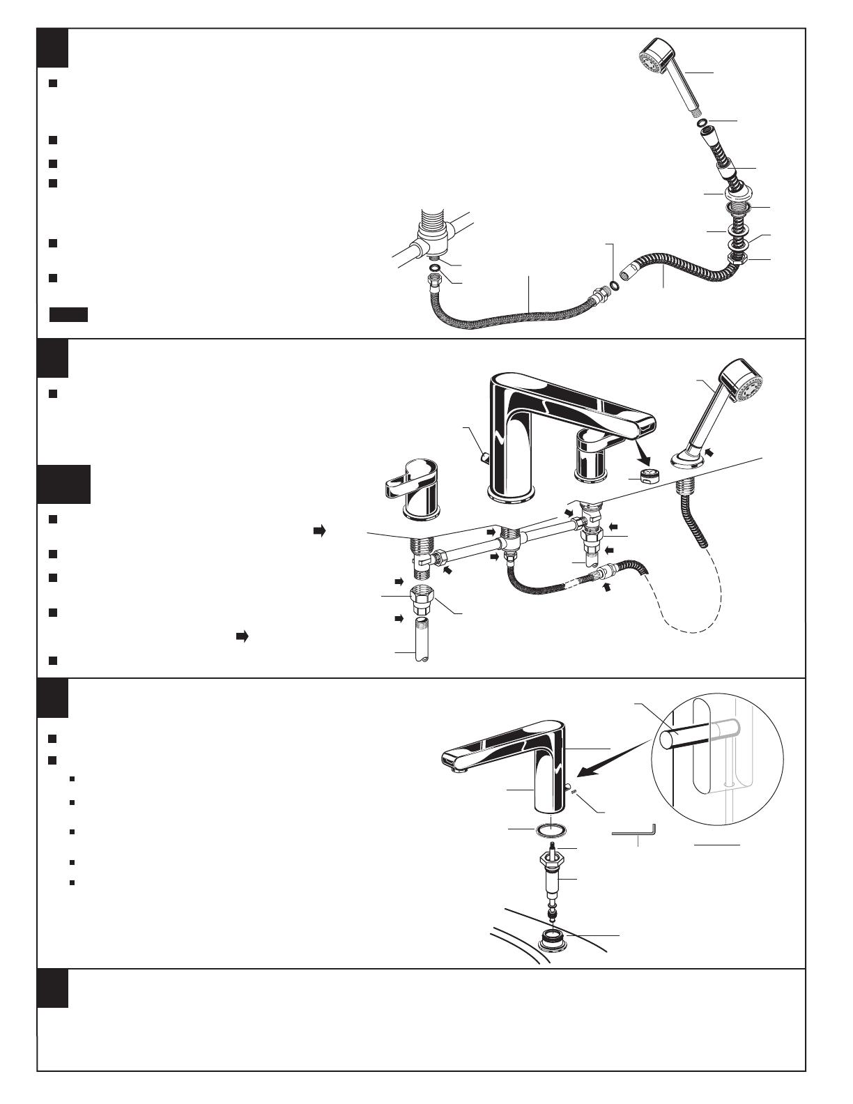
HANDSHOWER INSTALLATION (For 2590.901 only)
Drop SPRAY ESCUTCHEON (1) through the fourth hole of the tub ledge (12" max from SPOUT
center) with SPRAY ESCUTCHEON (1) directed towards tub center. Be sure RUBBER RING (2)
is properly seated in SPRAY ESCUTCHEON (1). Install RUBBER WASHER (3), BRASS WASHER (4)
and LOCKNUT (5) from underside of ledge.
Secure SPRAY ESCUTCHEON (1) by tightening LOCKNUT (5).
Install SEAL (9) and connect HOSE (10) to outlet nipple at the bottom of TEE (7). Tighten firmly.
Slip SHOWER HOSE (8) with COUPLING NUT through SPRAY
HOLDER (6) and SPRAY ESCUTCHEON (1). Note: SPRAY
HOLDER (6) must be seperate from ESCUTCHEON (1) to
pass HOSE (8) through ESCUTCHEON.(1)
Insert SEAL (9) into SHOWER HOSE (8). Connect HOSE (8)
to HOSE (10).
Install SEAL (9) and connect HAND SHOWER (11) to
SPRAY HOSE (8).
When not in use, HANDSHOWER should be seated
in the HOLDER.
NOTE
Before the bathroom is completely finished, you may
want to remove spout, handshower, and handles to
avoid damage during construction.
To remove handles, reverse steps in section 4.
To remove SPOUT (1), proceed as follows:
Unthread LIFT ROD KNOB (2) and remove.
Remove and remove SET SCREW (4) using 4mm hex
wrench supplied.
Lift SPOUT (1) off SHANK (5) carefully and remove RUBBER
RING (6).
Unthread SHANK SLEEVE (7) and remove from SHANK (5).
Reverse sequence to re-install SPOUT (1). Be sure RUBBER
RING (6) is properly seated in its recess at the base of the
SPOUT (1). Make certain SET SCREW (4) is properly aligned
and tight so that SPOUT (1) is locked in place.
6
1
2
3
5
7
8
10
9
9
9
11
1
8
4
2
4
6
6
5
7
VIEW "A"
VIEW "A"
7
MAKE WATER SUPPLY CONNECTIONS
8
9
7a
With HANDLES in OFF position, turn on WATER
SUPPLIES and check all connections for leaks.
Remove STREAM STRAIGHTENER (3).
Operate both HANDLES to flush water lines
thoroughly. Replace STREAM STRAIGHTENER (3).
Connect HOT water supply to LEFT INLET
UNION (1) and COLD water supply to
RIGHT INLET UNION (2). Pipe connections
are 3/4" NPT. Use sealant or Teflon tape
on pipe connections.
Do not solder directly to valve body.
TEST INSTALLED FAUCET
3/4" X 3/4" NPT UNION
(NOT SUPPLIED)
HOT
COLD
3/4" NPT
3/4" NPT
TRANSFER KNOB
2
3
1
Lift HAND SHOWER from HOLDER, direct spray
into tub. Lift TRANSFER KNOB to check HAND
SHOWER and HOSES for leaks.
Turn handles "off" and replace HAND SHOWER.
IMPORTANT: It is strongly recommended that access be
provided for all enclosed mechanical parts to this system.
M968627 Rev.1.2
DO: SIMPLY RINSE THE PRODUCT CLEAN WITH CLEAR WATER. DRY WITH A SOFT COTTON FLANNEL CLOTH.
DO NOT: DO NOT CLEAN THE PRODUCT WITH SOAPS, ACID, POLISH, ABRASIVES, HARSH CLEANERS, OR A
CLOTH WITH A COARSE SURFACE.
CARE INSTRUCTIONS:
HAND
SHOWER
  • Page 1 1
  • Page 2 2
  • Page 3 3

American Standard 2590.900.295 Installation guide

Category
Sanitary ware
Type
Installation guide
This manual is also suitable for

American Standard 2590.900.295 is a studio deck mount bath filler with a spout assembly, valve assembly, and handshower installation. It features adjustable handles that rotate 90 degrees, a 12-inch maximum reach from the spout center, and 3/4-inch NPT male valve inlets. The included spray escutcheon and rubber ring ensure proper seating and prevent leaks. The handshower hose connects to the outlet nipple at the bottom of the tee for added functionality.

Ask a question and I''ll find the answer in the document

Finding information in a document is now easier with AI