
QUESTIONS?
As a manufacturer, we are
committed to providing complete
customer satisfaction. If you
have questions, or if there are
missing or damaged parts, we
will guarantee complete satisfac-
tion through direct assistance
from our factory.
TO AVOID UNNECESSARY
DELAYS, PLEASE CALL DIRECT
TO OUR TOLL-FREE CUSTOMER
HOT LINE. The trained techni-
cians on our customer hot line
will provide immediate assis-
tance, free of charge to you.
CUSTOMER HOT LINE:
1-800-999-3756
Mon.ÐFri., 6 a.m.Ð6 p.m. MST
CAUTION
Read all precautions and in-
structions in this manual before
using this equipment. Save this
manual for future reference.
USERÕS MANUAL
Write the serial number in the space
above for future reference.
Model No. WLEX22080
Serial No.
Serial Number Decal
Patent Pending

2
TABLE OF CONTENTS
IMPORTANT PRECAUTIONS . . . . . . . . . . . . . . . . . . . . . . . . . . . . . . . . . . . . . . . . . . . . . . . . . . . . . . . . . . . . .2
BEFORE YOU BEGIN . . . . . . . . . . . . . . . . . . . . . . . . . . . . . . . . . . . . . . . . . . . . . . . . . . . . . . . . . . . . . . . . . . .3
ASSEMBLY . . . . . . . . . . . . . . . . . . . . . . . . . . . . . . . . . . . . . . . . . . . . . . . . . . . . . . . . . . . . . . . . . . . . . . . . . . .4
HOW TO USE THE WESLO 605s . . . . . . . . . . . . . . . . . . . . . . . . . . . . . . . . . . . . . . . . . . . . . . . . . . . . . . . . . .6
MAINTENANCE AND TROUBLE-SHOOTING . . . . . . . . . . . . . . . . . . . . . . . . . . . . . . . . . . . . . . . . . . . . . . . . .8
CONDITIONING GUIDELINES . . . . . . . . . . . . . . . . . . . . . . . . . . . . . . . . . . . . . . . . . . . . . . . . . . . . . . . . . . . . .9
PART LIST . . . . . . . . . . . . . . . . . . . . . . . . . . . . . . . . . . . . . . . . . . . . . . . . . . . . . . . . . . . . . . . . . . . . . . . . . . .10
EXPLODED DRAWING . . . . . . . . . . . . . . . . . . . . . . . . . . . . . . . . . . . . . . . . . . . . . . . . . . . . . . . . . . . . . . . . .11
ORDERING REPLACEMENT PARTS . . . . . . . . . . . . . . . . . . . . . . . . . . . . . . . . . . . . . . . . . . . . . . . .Back Cover
LIMITED WARRANTY . . . . . . . . . . . . . . . . . . . . . . . . . . . . . . . . . . . . . . . . . . . . . . . . . . . . . . . . . . .Back Cover
1. It is the responsibility of the owner to ensure
that all users are adequately informed of all
warnings and precautions.
2. Read all instructions in this manual before
using the WESLO 605s. Use the WESLO 605s
only as described.
3. Place the WESLO 605s on a level surface.
Cover the floor beneath the WESLO 605s to
protect the floor or carpet.
4. Inspect and tighten all parts regularly. Make
sure that the chain is properly adjusted (see
MAINTENANCE AND TROUBLE-SHOOTING
on page 8). Replace any worn parts immedi-
ately.
5. Keep children under age 12 and pets away
from the WESLO 605s at all times.
6. The WESLO 605s should not be used by
persons weighing more than 250 pounds.
7. Keep hands and feet away from the link arms
and other moving parts.
8. Do not wear loose clothing that could
become caught on the WESLO 605s. Always
wear athletic shoes for foot protection.
9. When adjusting the seat, insert the seat knob
through one of the holes in the seat post (see
the drawing on page 3). Do not insert the seat
knob under the seat post.
10. If you feel faint, dizzy, or short of breath while
exercising, stop immediately and begin cool-
ing down.
11. The WESLO 605s is intended for home use
only. Do not use the WESLO 605s in any com-
mercial, rental, or institutional setting.
12. The decal shown below has been placed on
the WESLO 605s. If the decal is missing, or if
it is not legible, please call our Customer
Service Department, toll-free, to order a free
replacement decal (see ORDERING REPLACE-
MENT PARTS on the back cover of this manu-
al). Apply the decal in the location shown.
IMPORTANT PRECAUTIONS
WARNING: To reduce the risk of serious injury, read the following important precautions before
using the WESLO 605s.
WARNING: Before beginning this or any exercise program, consult your physician. This is especially
important for persons over the age of 35 or persons with pre-existing health problems. Read all
instructions before using. ICON assumes no responsibility for personal injury or property damage
sustained by or through the use of this product.
Do not allow children on or
around machine.
Keep hands and feet away
from moving parts and contact
points.
Read owner's manual and
follow instructions.
!

3
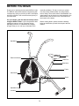
BEFORE YOU BEGIN
Pedal
Side Shield
Link Arm
Adjustable Cap
Electronic Monitor
Handlebar
Seat Knob
Seat
Seat Post
Frame
Thank you for selecting the innovative WESLO
¨
605s.
The WESLO 605s blends advanced engineering with
contemporary styling to provide you with a low-impact,
total body workout in the convenience and privacy of
your own home.
For your benefit, read this manual carefully before
using the WESLO
¨
605s. If you have questions after
reading the manual, call our Customer Service
Department toll-free at 1-800-999-3756, Monday
through Friday, 6 a.m. until 6 p.m. Mountain Time
(excluding holidays). To help us assist you, please
note the product model number and serial number
before calling. The model number is WLEX22080. The
serial number can be found on a decal attached to the
WESLO 605s (see the front cover of this manual for
the location of the decal).
Before reading further, please review the drawing
below and familiarize yourself with the parts that are
labeled.

4
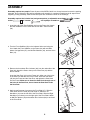
ASSEMBLY
1. Insert the end of the Rear Stabilizer (34) into the Frame (46). Attach
the Rear Stabilizer to the Frame with the four M5 x 12mm Screws
(56).
2. Turn the Front Stabilizer (59) so the indented holes are facing the
floor. Attach the Front Stabilizer to the Frame (46) with two M8 x
48mm Carriage Bolts (57), two M8 Zinc Washers (43), and two Acorn
Nuts (12).
3. Remove the three 8mm Zinc Locknuts (36) from the underside of the
Seat (40). Attach the Seat to the top of the Seat Post (41) with the
three Locknuts.
Insert the Seat Post (41) into the Frame (46). Align one of the holes
in the Seat Post with the hole in the Frame. Insert the Seat Knob
(45) into the Frame and the Seat Post, and tighten the Seat Knob
into the Frame. Make sure to insert the Seat Knob through one of
the holes in the Seat Post; do not insert the Seat Knob under
the Seat Post.
4. Apply a small amount of grease to the Pivot Shaft (17). Slide the
Pivot Shaft into the Frame (46) and center it. Slide the Left
Handlebar (10) onto the left end of the Pivot Shaft. Slide the Right
Handlebar (not shown) onto the right end of the Pivot Shaft. Attach
an M8 Zinc Washer (43) and an 8mm Zinc Locknut (36) to each end
of the Pivot Shaft.
1
56
34
46
12
57
59
36
40
41
45
46
43
43
46
2
3
46
17
10
36
43
4
Assembly requires two people. Place all parts of the WESLO 605s in a cleared area and remove the packing
materials. Do not dispose of the packing materials until assembly is completed. Read through all steps before
beginning. During assembly, make sure that all parts are oriented as shown in the drawings.
Assembly requires the included tool and grease packet, an adjustable wrench , a rubber
mallet , a hammer and a phillips screwdriver .

5
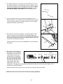
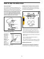
5. The Electronic Monitor (19) requires two ÒAAÓ batteries (not includ-
ed). Alkaline batteries are recommended. Open the battery cover on
the back of the Monitor. Insert two batteries into the Monitor. Make
sure that the negative ends of the batteries (marked ÒÐÓ) are
touching the springs in the Monitor. Close the battery cover.
6. Connect the Sensor Wire (47) into the wire extending from the
Electronic Monitor (19). Slide the Electronic Monitor onto the bracket
on the Frame (46). Make sure that the Sensor Wire is not pinched
between the Monitor and the Frame.
7. This step may have been completed. If not, please apply a small
amount of grease to the bolt welded in the Right Handlebar (38).
Connect a Link Arm (26) to the lower end of the Right Handlebar (38)
with a Brass Handlebar Bushing (27), an M8 Zinc Washer (43), and
an 8mm Zinc Locknut (36) as shown.
Attach the other Link Arm to the Left Handlebar in the same manner
(not shown).
47
46
26
36
43
27
38
19
8. Note: Apply a small amount of
grease to all of the small parts
assembled in this step. Slide a
13mm Washer (23) onto the
indicated end of a Pedal Axle
(24). Insert the Pedal Axle into
the right Link Arm (26). Slide a
Steel Link Arm Bushing (32), a
13mm Washer (23), and a
Pedal Spacer (33) onto the
Pedal Axle. Firmly tighten the Pedal Axle clockwise into the right arm of the Crank (39). Tighten a 1/2Ó
Locknut (22) onto the Pedal Axle.
Attach the other Pedal to the left arm of the Crank (not shown) in the same manner.
9. Make sure that all parts of the exercise bike are properly tightened.
5
6
7
Batteries
Cover
19
11 24 23 26 32 23 33 39 22
8

6
SEAT ADJUSTMENT
As you pedal, there should be a slight bend in your
knees when the pedals are at the lowest position. To
adjust the seat, first hold the seat and unscrew the
seat knob. Align one of the holes in the seat post with
the hole in the frame. Insert the seat knob into the
frame and the seat post, and tighten the seat knob
into the frame. Make sure to insert the seat knob
through one of the holes in the seat post; do not
insert the seat knob under the seat post.
LEVELING THE WESLO 605s
If the exercise
bike does not
rest evenly on
the floor, the
problem may
be corrected
with the
adjustable caps
on the front
stabilizer.
Rotate one or
both caps until
the exercise
bike rests evenly on the floor.
DESCRIPTION OF THE ELECTRONIC MONITOR
The electronic monitor features five modes that pro-
vide instant exercise feedback during your workouts.
The modes are described below.
¥ SpeedÑDisplays your speed, in miles per hour.
¥ TimeÑDisplays the length of time you have exer-
cised. Note: If you stop pedaling for ten seconds or
longer, the time mode will pause until you resume.
¥ DistanceÑDisplays the total distance you have ped-
aled, in miles.
¥ CalorieÑDisplays the approximate number of
Calories you have burned.
¥ ScanÑDisplays the speed, time, distance, and calo-
rie modes, for 5 seconds each, in a repeating cycle.
BATTERY INSTALLATION
Before the electronic monitor can be operated, two
ÒAAÓ batteries must be installed. If you have not
installed batteries, see assembly step 5 on page 5.
Front Stabilizer
Adjustable Cap
HOW TO USE THE WESLO 605s
Mode
Indicators
Display
Seat Knob
Seat Post
Seat
Frame

7
HOW TO OPERATE THE ELECTRONIC MONITOR
1. To turn on the power, press the on/reset button or
simply begin pedaling. When the power is turned
on, the entire display will appear for two seconds.
The electronic monitor will then be ready for opera-
tion.
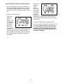
2. Select one of the five modes:
Scan modeÑ
When the
power is
turned on, the
scan mode will
automatically
be selected.
One mode
indicator will
show that the
scan mode is selected, and a flashing mode indica-
tor will show which mode is currently displayed.
Note: If a different mode is selected, you can select
the scan mode again by repeatedly pressing the
mode button.
Speed, time,
distance or
calorie
modeÑTo
select one of
these modes
for continu-
ous display,
press the
mode button
repeatedly. The mode indicators will show which
mode is selected. (Make sure that the scan mode is
not selected.)
3. To reset the display, press the on/reset button.
4. To turn off the power, simply wait for about four min-
utes. Note: The monitor has an Òauto-offÓ fea-
ture. If the pedals are not moved and the moni-
tor buttons are not pressed for four minutes,
the power will turn off automatically in order to
conserve the batteries.

8
Inspect and tighten all parts of the WESLO 605s
regu-larly. Replace any worn parts immediately.
The WESLO 605s can be cleaned with a soft, damp
cloth. Keep liquid away from the electronic monitor.
Keep the monitor out of direct sunlight or the display
may be damaged. Remove the batteries when storing
the WESLO 605s.
ELECTRONIC MONITOR TROUBLE-SHOOTING
If the electronic monitor does not function properly,
the batteries should be replaced. See assembly step
5 on page 5 for instructions. In addition, make sure
that the sensor wire is connected to the wire on the
monitor. See assembly step 6 on page 5.
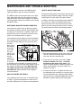
If the electronic monitor displays incorrect information,
the reed switch should be checked. First, remove the
pedal and the side shield from one side of the exer-
cise bike.
Next, refer to
the drawing
at the right
and locate
the reed
switch. Turn
the sprocket
until the
magnet on
the sprocket
is as close
as possible to the reed switch. Loosen the screw in
the reed switch, move the reed switch slightly closer to
the magnet, and tighten the screw. Make sure that
the magnet will not hit the reed switch when the
sprocket turns. Repeat until the monitor displays
correct information.
HOW TO TIGHTEN THE PEDALS
If the pedals become loose, refer to assembly step 8
on page 5. Tighten the pedal axles into the arms of
the crank. Tighten the 1/2" locknuts on the pedal axles.
HOW TO ADJUST THE CHAIN
The exercise bike features a precision chain that must
be kept properly lubricated. Apply a few drops of light
multi-purpose oil to the chain every three months.
In addition, the chain must be kept properly adjusted.
If the chain is too tight, the bearings may be dam-
aged; if the chain is too loose, the fan may be dam-
aged. If the chain causes excessive noise or slips as
you pedal, check the chain in the following manner:
1. Remove the fan guards from the front of the exer-
cise bike. Remove the pedal and the side shield
from one side of the exercise bike.
2. Press down on the center of the chain. There
should be between 1/4Ó and 1Ó of vertical
movement in the center of the chain. If the
chain is properly adjusted, reattach the pedal, side
shield, and fan guards. If the chain needs to be
adjusted, see step 3.
3. Loosen both axle nuts. To tighten the chain, turn
the adjustment nuts clockwise; to loosen the chain,
turn the adjustment nuts counterclockwise. Make
sure that the fan is straight and tighten the axle nuts.
Reattach the pedal, side shield, and fan guards.
MAINTENANCE AND TROUBLE-SHOOTING
Axle Nut
Fan
Adjustment Nuts
Magnet
Screw
Reed
Switch

9
The following general guidelines will help you to plan
your exercise program. Remember that proper nutri-
tion and adequate rest are essential for successful
results.
EXERCISE INTENSITY
Whether your goal is to burn fat or strengthen your
cardiovascular system, the key to achieving the
desired results is to exercise with the proper intensity.
The proper intensity level can be found by using your
heart rate as a guide. The chart below shows recom-
mended heart rates for fat burning, maximum fat burn-
ing, and cardiovascular (aerobic) exercise.
To find the proper heart rate for you, first find your age
near the bottom of the chart (ages are rounded off to
the nearest ten years). Next, find the three numbers
above your age. The three numbers are your Òtraining
zone.Ó The lowest number is the recommended heart
rate for fat burning; the middle number is the recom-
mended heart rate for maximum fat burning; the high-
est number is the recommended heart rate for aerobic
exercise.
Fat Burning
To burn fat effectively, you must exercise at a relative-
ly low intensity level for a sustained period of time.
During the first few minutes of exercise, your body
uses easily accessible carbohydrate calories for ener-
gy. Only after the first few minutes of exercise does
your body begin to use stored fat calories for energy. If
your goal is to burn fat, adjust your pace until your
heart rate is near the lowest number in your training
zone as you exercise.
For maximum fat burning, adjust your pace until your
heart rate is near the middle number in your training
zone as you exercise.
Aerobic Exercise
If your goal is to strengthen your cardiovascular sys-
tem, your exercise must be Òaerobic.Ó Aerobic exercise
is activity that requires large amounts of oxygen for
prolonged periods of time. This increases the demand
on the heart to pump blood to the muscles, and on the
lungs to oxygenate the blood. For aerobic exercise,
adjust your pace until your heart rate is near the high-
est number in your training zone as you exercise.
HOW TO MEASURE YOUR HEART RATE
To measure your heart rate, first exercise for at least
four minutes. Then, stop exercising and place two
fingers on your
wrist as shown.
Take a six-
second heart-
beat count, and
multiply the
result by 10 to
find your heart
rate. For
example, if your
six-second
heartbeat count
is 14, your heart
rate is 140 beats per minute. (A six-second count is
used because your heart rate will drop rapidly when
you stop exercising.) Adjust the intensity of your
exercise until your heart rate is at the desired level.
WORKOUT GUIDELINES
Each workout should include three important parts: a
warm-up, training zone exercise, and a cool-down.
A Warm-up
Start each workout with 5 to 10 minutes of stretching
and light exercise. A proper warm-up increases your
body temperature, heart rate, and circulation in prepa-
ration for strenuous exercise.
CONDITIONING GUIDELINES
WARNING: Before beginning this or any exercise
program, consult your physician. This is espe-
cially important for individuals over the age of 35
or individuals with pre-existing health problems.

10
PART LISTÑModel No. WLEX22080 R0598A
Key No. Qty. Description
1 2 Axle Nut
2 1 Fan Plate
3 1 Short Spacer
4 1 Fan Sprocket
5 1 Fan Axle Shaft
6 3 Flange Bushing
7 1 Fan Assembly
8 4 Handlebar Cap
9 2 Foam Grip
10 1 Left Handlebar
11 2 Pedal
12 2 Acorn Nut
13 2 8mm x 16mm Zinc Washer
14 2 Outer Pivot Bushing
15 1 Left Side Shield
16 2 Adjustable Cap
17 1 Pivot Shaft
18 2 Pedal Cap
19 1 Electronic Monitor
20 1 Crank/Sprocket
21 3 M4 x 25mm Screw
22 2 1/2Ó Zinc Locknut
23 4 13mm Zinc Washer
24 2 Pedal Axle
25 2 Fan Nut
26 2 Link Arm
27 2 Brass Handlebar Bushing
28 4 Inner Pivot Bushing
29 2 Adjustment Nut
30 2 Formed Washer
31 2 Adjustment Bolt
Key No. Qty. Description
32 2 Steel Link Arm Bushing
33 2 Pedal Spacer
34 1 Rear Stabilizer
35 2 Stabilizer Cap
36 7 8mm Zinc Locknut
37 2 Fan Guard
38 1 Right Handlebar
39 1 Crank/Sprocket Assembly
40 1 Seat
41 1 Seat Post
42 2 Pedal Locknut
43 6 M8 Zinc Washer
44 1 Seat Post Bushing
45 1 Seat Knob
46 1 Frame
47 1 Sensor Wire
48 1 Sensor Magnet
49 4 Fan Guard Clip
50 1 Long Spacer
51 1 Right Side Shield
52 1 Chain
53 1 M10 Flat Washer
54 1 Fan Guard Bracket
55 10 Self-tapping Screw
56 6 M5 x 12mm Screw
57 2 M8 x 48mm Carriage Bolt
58 1 Sensor Screw
59 1 Front Stabilizer
# 1 UserÕs Manual
# 1 Caution Decal
Note: Ò#Ó indicates a non-illustrated part. Specifications are subject to change without notice. See the back cover
of this manual for information about ordering replacement parts.
Training Zone Exercise
After warming up, increase the intensity of your exer-
cise until your heart rate is in your training zone for 20
to 30 minutes. (During the first few weeks of your
exercise program, do not keep your heart rate in your
training zone for longer than 20 minutes.)
A Cool-down
Finish each workout with 5 to 10 minutes of stretching.
This will increase the flexibility of your muscles and
will help to prevent post-exercise problems.
Exercise Frequency
To maintain or improve your condition, complete three
workouts each week, with at least one day of rest
between workouts. After a few months of regular exer-
cise, you may complete up to five workouts each week
if desired.
The key to success is to make exercise a regular and
enjoyable part of your everyday life.

6
23
41
22
46
44
8
9
38
15
19
33
36
56
47
28
56
17
45
32
47
48
52
40
25
3
4
21
4
2
6
7
6
50
53
25
8
9
23
11
10
24
13
42
18
1
20
33
32
23
24
11
42
13
18
56
1
22
51
16
16
57
26
36
43
59
27
8
31
30
29
30
29
55
34
35
55
55
27
43
36
8
5
54
49
37
26
49
43
12
39
Crank Assembly
58
23
28
35
36
55
55
28
14
43
36
14
36
43
EXPLODED DRAWINGÑModel No. WLEX22080 R0598A
11

Part No. 146550 H01071-C R0598A Printed in China © 1998 ICON Health & Fitness, Inc.
HOW TO ORDER REPLACEMENT PARTS
To order replacement parts, simply call our Customer Service Department toll-free at 1-800-999-3756, Monday
through Friday, 6 a.m. until 6 p.m. Mountain Time (excluding holidays). To help us assist you, please be
prepared to give the following information when calling:
¥ The MODEL NUMBER of the product (WLEX22080).
¥ The NAME of the product (WESLO
¨
605s).
¥ The SERIAL NUMBER of the product (see the front cover of this manual).
¥ The KEY NUMBER and DESCRIPTION of the part(s) from page 10 of this manual.
LIMITED WARRANTY
ICON Health & Fitness, Inc. (ICON) warrants this product to be free from defects in workmanship and
material, under normal use and service conditions, for a period of ninety (90) days from the date of pur-
chase. This warranty extends only to the original purchaser. ICON's obligation under this warranty is lim-
ited to replacing or repairing, at ICON's option, the product at one of its authorized service centers. All
products for which warranty claim is made must be received by ICON at one of its authorized service cen-
ters with all freight and other transportation charges prepaid, accompanied by sufficient proof of purchase.
All returns must be pre-authorized by ICON. This warranty does not extend to any product or damage to
a product caused by or attributable to freight damage, abuse, misuse, improper or abnormal usage or
repairs not provided by an ICON authorized service center, to products used for commercial or rental pur-
poses, or to products used as store displays. No other warranty beyond that specifically set forth above
is authorized by ICON.
ICON is not responsible or liable for indirect, special or consequential damages arising out of or in con-
nection with the use or performance of the product or damages with respect to any economic loss, loss
of property, loss of revenues or profits, loss of enjoyment or use, costs of removal, installation or other
consequential damages of whatsoever nature. Some states do not allow the exclusion or limitation of inci-
dental or consequential damages. Accordingly, the above limitation may not apply to you.
The warranty extended hereunder is in lieu of any and all other warranties and any implied warranties of
merchantability or fitness for a particular purpose is limited in its scope and duration to the terms set forth
herein. Some states do not allow limitations on how long an implied warranty lasts. Accordingly, the above
limitation may not apply to you.
This warranty gives you specific legal rights. You may also have other rights which vary from state to state.
ICON HEALTH & FITNESS, INC., 1500 S. 1000 W., LOGAN, UT 84321-9813
WESLO is a registered trademark of ICON Health & Fitness, Inc.
-
 1
1
-
 2
2
-
 3
3
-
 4
4
-
 5
5
-
 6
6
-
 7
7
-
 8
8
-
 9
9
-
 10
10
-
 11
11
-
 12
12


Weslo 605s User manual
- Type
- User manual
- This manual is also suitable for
Ask a question and I''ll find the answer in the document
Finding information in a document is now easier with AI
Related papers
-
Weslo Aero 640 User manual
-
-
-
-
-
-
-
-
-