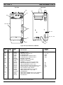
ESAB PCM-500i Plasma Arc Cutting Packages User manual
- Category
- Welding System
- Type
- User manual

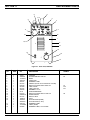
INSTRUCTION MANUAL
PCM-500i
PLASMA ARC CUTTING PACKAGES
These INSTRUCTIONS are for experienced operators. If you are not fully familiar with the principles of operation and
safe practices for arc welding equipment, we urge you to read our booklet, "Precautions and Safe Practices for Arc
Welding, Cutting, and Gouging," Form 52-529. Do NOT permit untrained persons to install, operate, or maintain this
equipment. Do NOT attempt to install or operate this equipment until you have read and fully understand these
instructions. If you do not fully understand these instructions, contact your supplier for further information. Be sure
to read the Safety Precautions before installing or operating this equipment.
F-15-296-E
Feb., 2004
This manual provides complete instructions for the following PCM-500i cutting packages starting with Serial No. PORI612001:
ESAB P/N 36314 - 208/230 V, 1-Phase, 50/60 Hz
ESAB P/N 36316 - 400 V (380/415 V), 3-Phase, 50/60 Hz
Be sure this information reaches the operator.
You can get extra copies through your supplier.

USER RESPONSIBILITY
This equipment will perform in conformity with the description thereof contained in this manual and accompanying
labels and/or inserts when installed, operated, maintained and repaired in accordance with the instructions pro-
vided. This equipment must be checked periodically. Malfunctioning or poorly maintained equipment should not
be used. Parts that are broken, missing, worn, distorted or contaminated should be replaced immediately. Should
such repair or replacement become necessary, the manufacturer recommends that a telephone or written request
for service advice be made to the Authorized Distributor from whom purchased.
This equipment or any of its parts should not be altered without the prior written approval of the manufacturer. The
user of this equipment shall have the sole responsibility for any malfunction which results from improper use, faulty
maintenance, damage, improper repair or alteration by anyone other than the manufacturer or a service facility
designated by the manufacturer.
TABLE OF CONTENTS
SECTION TITLE PAGE
PARAGRAPH
SECTION 1 DESCRIPTION ................................................................................................. 7
1.1 General ............................................................................................................. 7
1.2 Scope ................................................................................................................ 7
1.3 Packages Available ........................................................................................... 7
1.4 Specifications .................................................................................................... 8, 9
1.5 Optional Accessories ........................................................................................ 9
SECTION 2 INSTALLATION ................................................................................................ 10
2.1 General ............................................................................................................. 10
2.2 Equipment Required ......................................................................................... 10
2.3 Location ............................................................................................................ 10
2.4 Inspection.......................................................................................................... 10
2.5 Primary Electrical Input Connections................................................................. 10
2.6 Secondary (Output) Connections ...................................................................... 11
2.7 Connecting PCM-500i for 200(208) Vac Input ................................................... 13
SECTION 3 OPERATION ..................................................................................................... 15
3.1 Operation .......................................................................................................... 15
3.2 PCM-500i Controls ............................................................................................ 15
3.3 Assembling PT-31XL Consumable Parts .......................................................... 16
3.4 Cutting with the PT-31XL .................................................................................. 16
3.5 Operating Techniques ....................................................................................... 17
3.6 Common Cutting Problems ............................................................................... 18
SECTION 4 MAINTENANCE ................................................................................................ 19
4.1 General ............................................................................................................. 19
4.2 Inspection and Cleaning .................................................................................... 19
4.3 Flow Switch ....................................................................................................... 19
SECTION 5 TROUBLESHOOTING ..................................................................................... 20
5.1 Troubleshooting ................................................................................................ 20
5.2 Troubleshooting Guide ...................................................................................... 20
5.3 Sequence of Operation ..................................................................................... 25
SECTION 6 REPLACEMENT PARTS .................................................................................. 33
6.1 General ............................................................................................................. 33
6.2 Ordering ............................................................................................................ 33
2

3
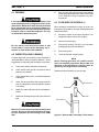
WARNING: These Safety Precautions are for
your protection. They summarize precaution-
ary information from the references listed in
Additional Safety Information section. Before
performing any installation or operating procedures, be
sure to read and follow the safety precautions listed below
as well as all other manuals, material safety data sheets,
labels, etc. Failure to observe Safety Precautions can result
in injury or death.
PROTECT YOURSELF AND OTHERS
--
Some welding, cutting, and gouging
processes are noisy and require ear
protection. The arc, like the sun, emits
ultraviolet (UV) and other radiation and
can injure skin and eyes. Hot metal can cause burns.
Training in the proper use of the processes and equip-
ment is essential to prevent accidents. Therefore:
1. Always wear safety glasses with side shields in any work
area, even if welding helmets, face shields, and goggles
are also required.
2. Use a face shield fitted with the correct filter and cover
plates to protect your eyes, face, neck, and ears from
sparks and rays of the arc when operating or observing
operations. Warn bystanders not to watch the arc and
not to expose themselves to the rays of the electric-arc
or hot metal.
3. Wear flameproof gauntlet type gloves, heavy long-sleeve
shirt, cuffless trousers, high-topped shoes, and a weld-
ing helmet or cap for hair protection, to protect against
arc rays and hot sparks or hot metal. A flameproof apron
may also be desirable as protection against radiated
heat and sparks.
4. Hot sparks or metal can lodge in rolled up sleeves,
trouser cuffs, or pockets. Sleeves and collars should be
kept buttoned, and open pockets eliminated from the
front of clothing
5. Protect other personnel from arc rays and hot sparks
with a suitable non-flammable partition or curtains.
6. Use goggles over safety glasses when chipping slag or
grinding. Chipped slag may be hot and can fly far.
Bystanders should also wear goggles over safety glasses.
FIRES AND EXPLOSIONS -- Heat from
flames and arcs can start fires. Hot slag
or sparks can also cause fires and ex-
plosions. Therefore:
1. Remove all combustible materials well away from the
work area or cover the materials with a protective non-
flammable covering. Combustible materials include wood,
cloth, sawdust, liquid and gas fuels, solvents, paints and
coatings, paper, etc.
2. Hot sparks or hot metal can fall through cracks or
crevices in floors or wall openings and cause a hidden
smoldering fire or fires on the floor below. Make certain
that such openings are protected from hot sparks and
metal.“
3. Do not weld, cut or perform other hot work until the
workpiece has been completely cleaned so that there
are no substances on the workpiece which might pro-
duce flammable or toxic vapors. Do not do hot work on
closed containers. They may explode.
4. Have fire extinguishing equipment handy for instant use,
such as a garden hose, water pail, sand bucket, or
portable fire extinguisher. Be sure you are trained in its
use.
SAFETY PRECAUTIONS
10/98
5. Do not use equipment beyond its ratings. For example,
overloaded welding cable can overheat and create a fire
hazard.
6. After completing operations, inspect the work area to
make certain there are no hot sparks or hot metal which
could cause a later fire. Use fire watchers when neces-
sary.
7. For additional information, refer to NFPA Standard 51B,
"Fire Prevention in Use of Cutting and Welding Pro-
cesses", available from the National Fire Protection Asso-
ciation, Batterymarch Park, Quincy, MA 02269.
ELECTRICAL SHOCK -- Contact with live
electrical parts and ground can cause
severe injury or death. DO NOT use AC
welding current in damp areas, if move-
ment is confined, or if there is danger of
falling.
1. Be sure the power source frame (chassis) is connected
to the ground system of the input power.
2. Connect the workpiece to a good electrical ground.
3. Connect the work cable to the workpiece. A poor or
missing connection can expose you or others to a fatal
shock.
4. Use well-maintained equipment. Replace worn or dam-
aged cables.
5. Keep everything dry, including clothing, work area, cables,
torch/electrode holder, and power source.
6. Make sure that all parts of your body are insulated from
work
and from ground.
7. Do not stand directly on metal or the earth while working
in tight quarters or a damp area; stand on dry boards or
an insulating platform and wear rubber-soled shoes.
8. Put on dry, hole-free gloves before turning on the power.
9. Turn off the power before removing your gloves.
10. Refer to ANSI/ASC Standard Z49.1 (listed on next page)
for specific grounding recommendations. Do not mistake
the work lead for a ground cable.
ELECTRIC AND MAGNETIC FIELDS —
May be dangerous. Electric current flow-
ing through any conductor causes lo-
calized Electric and Magnetic Fields
(EMF). Welding and cutting current cre-
ates EMF around welding cables and
welding machines. Therefore:
1. Welders having pacemakers should consult their physi-
cian before welding. EMF may interfere with some pace-
makers.
2. Exposure to EMF may have other health effects which are
unknown.
3. Welders should use the following procedures to minimize
exposure to EMF:
A. Route the electrode and work cables together. Secure
them with tape when possible.
B. Never coil the torch or work cable around your body.
C. Do not place your body between the torch and work
cables. Route cables on the same side of your body.
D. Connect the work cable to the workpiece as close as
possible to the area being welded.
E. Keep welding power source and cables as far away
from your body as possible.

4
FUMES AND GASES -- Fumes and
gases, can cause discomfort or harm,
particularly in confined spaces. Do
not breathe fumes and gases. Shield-
ing gases can cause asphyxiation.
Therefore:
1. Always provide adequate ventilation in the work area by
natural or mechanical means. Do not weld, cut, or gouge
on materials such as galvanized steel, stainless steel,
copper, zinc, lead, beryllium, or cadmium unless positive
mechanical ventilation is provided. Do not breathe fumes
from these materials.
2. Do not operate near degreasing and spraying opera-
tions. The heat or arc rays can react with chlorinated
hydrocarbon vapors to form phosgene, a highly toxic
gas, and other irritant gases.
3. If you develop momentary eye, nose, or throat irritation
while operating, this is an indication that ventilation is not
adequate. Stop work and take necessary steps to im-
prove ventilation in the work area. Do not continue to
operate if physical discomfort persists.
4. Refer to ANSI/ASC Standard Z49.1 (see listing below)
for specific ventilation recommendations.
5. WARNING: This product, when used for welding or
cutting, produces fumes or gases which
contain chemicals known to the State of
California to cause birth defects and, in
some cases, cancer. (California Health &
Safety Code
§25249.5 et seq.)
CYLINDER HANDLING -- Cylinders, if
mishandled, can rupture and violently
release gas. Sudden rupture of cylin-
der, valve, or relief device can injure or
kill. Therefore:
1. Use the proper gas for the process and use the proper
pressure reducing regulator designed to operate from
the compressed gas cylinder. Do not use adaptors.
Maintain hoses and fittings in good condition. Follow
manufacturer's operating instructions for mounting regu-
lator to a compressed gas cylinder.
2. Always secure cylinders in an upright position by chain
or strap to suitable hand trucks, undercarriages, benches,
walls, post, or racks. Never secure cylinders to work
tables or fixtures where they may become part of an
electrical circuit.
3. When not in use, keep cylinder valves closed. Have
valve protection cap in place if regulator is not con-
nected. Secure and move cylinders by using suitable
hand trucks. Avoid rough handling of cylinders.
4. Locate cylinders away from heat, sparks, and flames.
Never strike an arc on a cylinder.
5. For additional information, refer to CGA Standard P-1,
"Precautions for Safe Handling of Compressed Gases in
Cylinders", which is available from Compressed Gas
Association, 1235 Jefferson Davis Highway, Arlington,
VA 22202.
EQUIPMENT MAINTENANCE -- Faulty or
improperly maintained equipment can
cause injury or death. Therefore:
1. Always have qualified personnel perform the installa-
tion, troubleshooting, and maintenance work. Do not
perform any electrical work unless you are qualified to
perform such work.
2. Before performing any maintenance work inside a power
source, disconnect the power source from the incoming
electrical power.
3. Maintain cables, grounding wire, connections, power
cord, and power supply in safe working order. Do not
operate any equipment in faulty condition.
4. Do not abuse any equipment or accessories. Keep
equipment away from heat sources such as furnaces,
wet conditions such as water puddles, oil or grease,
corrosive atmospheres and inclement weather.
5. Keep all safety devices and cabinet covers in position
and in good repair.
6. Use equipment only for its intended purpose. Do not
modify it in any manner.
ADDITIONAL SAFETY INFORMATION -- For
more information on safe practices for elec-
tric arc welding and cutting equipment, ask
your supplier for a copy of "Precautions and
Safe Practices for Arc Welding, Cutting and
Gouging", Form 52-529.
The following publications, which are available from the
American Welding Society, 550 N.W. LeJuene Road, Mi-
ami, FL 33126, are recommended to you:
1. ANSI/ASC Z49.1 - "Safety in Welding and Cutting"
2. AWS C5.1 - "Recommended Practices for Plasma Arc
Welding"
3. AWS C5.2 - "Recommended Practices for Plasma Arc
Cutting"
4. AWS C5.3 - "Recommended Practices for Air Carbon
Arc Gouging and Cutting"
5. AWS C5.5 - "Recommended Practices for Gas Tungsten
Arc Welding“
6. AWS C5.6 - "Recommended Practices for Gas Metal Arc
Welding"“
7. AWS SP - "Safe Practices" - Reprint, Welding Hand-
book.
8. ANSI/AWS F4.1, "Recommended Safe Practices for
Welding and Cutting of Containers That Have Held
Hazardous Substances."
MEANING OF SYMBOLS - As used through-
out this manual: Means Attention! Be Alert!
Your safety is involved.
Means immediate hazards which, if
not avoided, will result in immediate,
serious personal injury or loss of life.
Means potential hazards which could
result in personal injury or loss of life.
Means hazards which could result in
minor personal injury.
SP98-10
Page is loading ...
Page is loading ...

7
SECTION 1 DESCRIPTION
1.1 GENERAL
The PCM-500i is a compact, completely self-contained
plasma cutting system. As shipped, the system is fully
assembled and ready to cut after being connected to
input power and a source of prefiltered compressed air
(90-150 psi). The PCM-500i package uses the PT-31XL
torch to deliver cutting power for materials up to 1/2 inch
thick or for severing up to to 5/8-in. thick. Refer to the
following paragraphs for descriptions of the PCM-500i
packages available as well as performance specifica-
tions.
Do not use any torch with this power source other
than the ESAB brand PT-31XL torch. Serious injury
may occur if used with any other torch.
1.2 SCOPE
The purpose of this manual is to provide the operator with
all the information required to install and operate the
PCM-500i plasma arc cutting package. Technical refer-
ence material is also provided to assist in troubleshoot-
ing the cutting package.
1.3 PACKAGES AVAILABLE
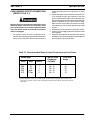
Table 1-1 lists available PCM-500i packages.
Table 1-1. PCM-500i Cutting Packages
Each PCM-500i Plasma Arc Cutting Package includes a Power Source, PT-31XL Torch with 25-ft. (8m) service lines,
and Torch Spare Parts Kit as listed.
Contents of PCM-500i Cutting Package, P/N
Package 36314 36316
PCM-500i Power Source with Regulator
and Work Cable
208/230 Vac, 1-phase, P/N 36304
400 Vac, 3-phase, P/N 36306
PT-31XL Torch Assembly, 25-ft (8m)*, P/N 21985
Spare Parts Kit (see Table 1-2 for contents) , P/N 0558003301
* PT-31XL torch assembly has front end parts assembled.

8
SECTION 1 DESCRIPTION
* Duty cycle is based on a 10-minute period; therefore, a 40% duty cycle means the machine may operate for 4 minutes with a cool down period of 6 minutes;
a 60% duty cycle means the machine may operate for 6 minutes with a cool down period of 4 minutes; a 100% duty cycle means the machine may operate
continuously.
** Includes 2.2-in. (56 mm) high handle.
Table 1-3. PCM-500i Specifications
1.4 SPECIFICATIONS
Refer to Tables 1-3, 1-4, and Figures 1-1 and 1-2 for PCM-500i technical specifications.
Table 1-2. PT-31XL Spare Parts Kit Contents
Description Part Number Quantity
Spare Parts Kit P/N 0558003301 includes:
35/40 A Nozzle 20860 3
Electrode 20862 2
Swirl Baffle 20463 1
Heat Shield 20282 1
NOTE: PT-31XL Torch Assembly P/N 21985 is supplied with the nozzle, electrode, swirl baffle, and heat shield assembled.
Rated
Output
40% Duty Cycle* 35 A @ 120 V dc
60% Duty Cycle* 30 A @ 120 V dc
100% Duty Cycle* 22 A @ 120 V dc
Output Current Range 10 to 35 Amperes
Open Circuit Voltage 265 V dc Nominal
Rated Primary Input
@
35 A @ 120 VDC Output
208/230 VAC, 1-Phase 30/25 A, 50/60 Hz
380/415 VAC, 3-Phase 8/7.5 A/Phase, 50/60 Hz
Power Factor @ 35 Amperes Output 81% (1-Phase)/94% (3-Phase)
Efficiency @ 35 Amperes Output 90% (Typical)
Current Capacity PT-31XL 50 A DCSP
Air Requirements PT-31XL 250 cfh @ 80 psi
Dimensions of PCM-500i
Length
Height
Width
19.3-in. ( 490 mm)
17.8-in. (452 mm)**
8.6-in. (218 mm)
Weight (less torch, work cable) 50 lbs (23 kg)

9
SECTION 1 DESCRIPTION
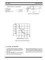
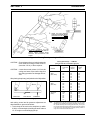
Figure 1-2. PT-31XL Cutting Performance
2 1/4"
(57mm)
5 1/4"
(133mm)
75° Torch
Table 1-4. PT-31XL Torch Specifications
PT-31XL Torch
Current Capacity ......................................50A DCSP
Shipping Wgt. .......................................... 2 lbs (1 kg)
Length of Service Lines ........................ 25-ft. (7.6 m)
Figure 1-1. PT-31XL Dimensions
1.5 OPTIONAL ACCESSORIES
1. Torch Wrap/Spare Parts Kit Holder, P/N 33952GY.
Units now have 4 mounting holes on left side for
mounting this accessory holder starting around Oc-
tober, 1996.
2. Wheel Cart, P/N 34324. This 5 7/8" high cart has
front swivel casters and rear casters to make it
easier to roll the PCM-500i around the job site.
3. Spare Parts Kits, P/N 19676. Recommended when
cutting below 20 amps. See Section 3.3 and Figure
3-2A. The kit includes; 4-Heat Sheld, P/N 20282; 4-
Nozzle, P/N 19667; 4-Electrode, P/N 18205; 1-Swirl
Baffle, P/N 18785; and 1 oz. Lubricant, P/N 17672.

SECTION 2 INSTALLATION
10
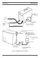
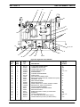
2.5 PRIMARY ELECTRICAL INPUT
CONNECTIONS (FIGURE 2-1)
ELECTRIC SHOCK CAN KILL! Precautionary mea-
sures should be taken to provide maximum protec-
tion against electrical shock. Be sure that all power
is off by opening the line (wall) disconnect switch
and by unplugging the power cord to the unit when
connections are made inside of the power source.
Be sure that the power source is properly configured
for your input power supply. DO NOT connect a
power source configured for 208/230 V to a 460 V
input power supply. Damage to the machine may
occur.
The PCM-500i power source operating on 230 V, 1-
phase input power is equipped with a 10-ft, 3-conductor
cable with plug. An optional mating receptacle (P/N
674540) is available. A line (wall) disconnect switch with
a 40-ampere fuse or circuit breaker should be provided
at the main power panel. The cable connecting the
disconnect switch to the receptacle should include three
(two power and one ground) No. 10 AWG insulated
conductors.
The chassis must be connected to an approved
electrical ground. Failure to do so may result in
electrical shock, severe burns or death.
NOTE: If using 208 V input power, the PCM-500i must
be reconnected for 208 V use as directed in
Section 2.7 and Fig. 2-2.
For all other PCM-500i power sources, they are equipped
with a 10-ft, 4-conductor input power cord with no plug for
connecting to 3-phase power. A line (wall) disconnect
switch, with proper sized fuse or circuit breaker (see
Table 2.1), should be provided at the main power panel.
The customer may connect the input power cord directly
to the disconnect switch or purchase a proper plug and
receptacle from a local electrical supplier. The cable
connecting the disconnect switch to the receptacle should
include four (three power and one ground) No. 12 AWG
insulated conductors.
2.1 GENERAL
Proper installation can contribute materially to the satis-
factory and trouble-free operation of the PCM-500i cut-
ting package. It is suggested that each step in this
section be studied carefully and followed as closely as
possible.
2.2 EQUIPMENT REQUIRED
A source of clean, prefiltered dry air that supplies 250 cfh
at 80 psig is required for the cutting operation. The air
supply should not exceed 150 psig (the maximum inlet
pressure rating of the air filter-regulator supplied with the
package).
2.3 LOCATION
Adequate ventilation is necessary to provide proper
cooling of the PCM-500i and the amount of dirt, dust, and
excessive heat to which the equipment is exposed,
should be minimized. There should be at least one foot
of clearance between the PCM-500i power source and
wall or any other obstruction to allow freedom of air
movement through the power source.
Installing or placing any type of filtering device will restrict
the volume of intake air, thereby subjecting the power
source internal components to overheating. The war-
ranty is void if any type of filter device is used.
2.4 INSPECTION
A. Remove the shipping container and all packing
material and inspect for evidence of concealed
damage which may not have been apparant upon
receipt of the PCM-500i. Notify the carrier of any
defects or damage at once.
B. Check container for any loose parts prior to dispos-
ing of shipping materials.
C. Check air louvers and any other openings to ensure
that any obstruction is removed.

SECTION 2 INSTALLATION
11
output terminal board from right panel of power
source.
2. Thread the power cable and switch lead of the PT-
31XL through the right open bushing of the front
panel. Connect power cable to the torch fitting (left-
hand threads) and plug in the switch lead to the torch
switch receptable on the output terminal board.
Make sure the power cable connection is wrench-
tight. Make sure plug of switch lead is firmly locked
in place.
3. Reassemble the access door to the power source.
4. Connect your air supply to the inlet connection of the
filter-regulator.
5. Clamp the work cable to the workpiece. Be sure the
workpiece is connected to an approved earth ground
with a properly sized ground cable.
2.6 SECONDARY (OUTPUT) CONNECTIONS
(REFER TO FIG. 2-1)
Before making any connections to the power source
output terminals, make sure that all primary input
power to the power source is deenergized (off) at the
main disconnect switch and that the input power
cable is unplugged.
1. For operator safety, the torch connections are lo-
cated on the output terminal board behind the lower
portion of the front panel. Remove access door to
Table 2.1. Recommended Sizes for Input Conductors and Line Fuses
Rated Input Input & GND Fuse Size
Conductor Amps
Volts Amp Phases CU/AWG*
208 30 1 No. 10 40
230 25 1 No. 10 40
380 8/ph. 3 No. 12 15
415 7.5/ph. 3 No. 12 15
* Sized per National Code for 80°C rated copper conductors @ 30°C ambient. Not more than three
conductors in raceway or cable. Local codes should be followed if they specify sizes other than those
listed above.

SECTION 2 INSTALLATION
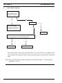
12
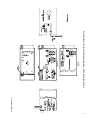
Figure 2-1. PCM-500i Interconnection Diagram
CUSTOMER FUSED LINE
DISCONNECT SWITCH
(See Table 2.1 and WARNING in
regards to chassis ground in Sec-
tion 2.5.)
See Table 2.1
WORK CABLE
SAFETY
GROUND
TORCH
POWER CABLE
CONNECTION
PT-31XL
WORK
PLUG
(Equipped only on
230 V, 1-phase units)
between work and power
source
Allow at least 10 ft (3 m)
ACCESS DOOR FOR
TORCH CONNECTION.
NOTE: If using 208 V input,
see Section 2.7 and
Fig. 2-2.
RECEPTACLE (P/N 674540)
(Optional for 208/230 V, 1-phase
power sources)
TORCH SWITCH
RECEPTACLE
Prefiltered AIR SUPPLY (Customer Supplied)
(90 to 150 psig max)

SECTION 2 INSTALLATION
13
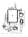
2.7 CONNECTING PCM-500I FOR 208 VAC IN-
PUT
ELECTRIC SHOCK CAN KILL! Precautionary mea-
sures should be taken to provide maximum protec-
tion against electrical shock. Be sure that all power
is off by opening the line (wall) disconnect switch
and by unplugging the power cord to the unit when
reconnecting for 208 Vac input.
The PCM-500i power source with 208/230 vac, 1-phase
input capability is factory set for 230 vac input. If using
208 vac input, the PCM-500i must be reconnected as
follows before connecting to your input power.
1. Remove cover from the PCM-500i power source.
2. Locate the input bridge (IBR) and the two-position
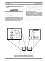
terminal block on the left side of the unit towards the
rear panel (see Fig. 1). Locate the gray wire con-
nected to TB5-2 and to IBR terminal "R". For 108
Vac input, disconnect the gray wire from TB5-2 and
then firmly connect it to TB5-1.
3. Locate the output bridge (D1) on the left side to-
wards the front panel (see fig. 2). Disconnect and
swap leads X2 and X3 from the main transformer.
For 208 Vac input, X2 is connected to TB3 and X3
is connected to terminal 3 of D1. Make sure the
connections are firmly tightened.
4. Leave all other wires the same.
5. Reinstall cover and connect the PCM-500i to the
208vac input power.
INPUT BRIDGE
+
~
~
OUTPUT
BRIDGE
Fig. 1
Fig. 2
Figure 2.2. Original Factory Setup for 230 Vac Input on
Power Source with 208/230 Vac Input Power Capability
D1

SECTION 2 INSTALLATION
14
Figure 2-3. Ground and Work Cable Connections
GROUNDED
WORK TABLE
EARTH GROUND
WORK CABLE
BE SURE WORK IS IN GOOD
CONTACT WITH TABLE.
WORK CABLE
EARTH GROUND
DO NOT ATTACH WORK
CABLE TO PIECE BEING CUT
FREE

SECTION 3 OPERATION
15
3.1 OPERATION
ELECTRIC SHOCK can kill.
• Do NOT operate the unit with the cover removed.
• Do NOT apply power to the unit while holding or
carrying the unit.
• Do NOT touch any torch parts forward of the torch
handle (nozzle, heat shield, electrode, etc.) with
power switch on.
ARC RAYS can burn eyes and skin;
NOISE can damage hearing.
• Wear welding helmet with No. 6 or 7 lens shade.
• Wear eye, ear, and body protection.
Position the PCM-500i at least 10 feet (3 meters) from
the cutting area. Sparks and hot slag from the cut-
ting operation can damage the unit.
Figure 3-1. PCM-500i Controls
AIR REGULATOR
CONTROL KNOB
POWER LIGHT (WHITE)
AIR PRESSURE
GAUGE
AIR CHECK
SWITCH
LOCK-IN
SWITCH
CURRENT
CONTROL KNOB
REAR
VIEW
POWER ON-OFF
(I-O) SWITCH &
CIRCUIT BREAKER
CIRCUIT
BREAKER (3A)
FAULT LIGHT (AMBER)
3.2 PCM-500i CONTROLS (FIGURE 3-1)
A. Power Switch (located on rear panel). When
placed in ON position, the white pilot light will glow
indicating control circuit is energized and the cool-
ing fan will run.
B. Output Current Control. Adjustable from 10 to
35 amperes to suit cutting conditions.
C. Air Check Switch. When placed in ON position,
air filter-regulator can be adjusted to desired pres-
sure (65-75 psig) before cutting operations. Allow
air to flow for a few minutes. This should remove
any condensation that may have accumulated
during shutdown period. Be sure to place switch
in OFF position before starting cutting operations.
D. Lock-In Switch. When placed in ON position,
permits releasing torch switch button after cutting
arc has been initiated. To extinguish arc at end of
cut, press and release torch switch button again or
pull torch away from work. When placed in OFF
position, torch switch must be held closely by the
operator during the entire cutting operation and
then released at the end of cut.

SECTION 3 OPERATION
16
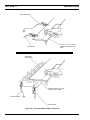
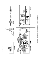
Fig. 3-2 - Assembly of “XT” Consumable Parts
NOTE: If cutting at less than 20 amps, standard
consumables illustrated below in Figure 3-2A
are recommended. These consumables are
supplied in Spare Parts Kit, P/N 19676. Air
presssure should be set at 40 to 50 psig.
BE SURE to install the swirl baffle in the torch.
Failure to do so would allow the nozzle (tip) to
contact the electrode. This contact would permit
high voltage to be applied to the nozzle. Your contact
with the nozzle or workpiece could then result in
serious injury or death by electric shock.
The PT-31XL torch head contains a gas flow check
valve that acts in conjunction with the flow switch
and circuitry within the power source. This system
prevents the torch from being energized with high
voltage if the torch switch is accidentally closed
when the hield is removed. ALWAYS REPLACE
TORCH WITH THE PROPER TORCH MANUFAC-
TURED BY ESAB SINCE IT ALONE CONTAINS
ESAB’S PATENTED SAFETY INTERLOCK.
For additional torch information, see booklet (F-14-246)
packed with the PT-31XL torch.
3.4 CUTTING WITH THE PT-31XL
Wear the usual protective gloves, clothing, and hel-
met. Helmet with filter lens shade No. 6 or 7 should
provide adequate protection for your eyes.
Never touch any parts forward of the torch handle
(tip, heat shield, electrode, etc.) unless the power
switch is in the OFF position.
NOTE: Nozzles
Marked By
Amperage
E. Fault Light. Will glow amber under the following
conditions and operations will come to a complete
stop.
Flow Fault: The fault light will be mostly on but
will flick off for about 1/10th of a second every
second. This indicates that the air flow supply is
low.
Over Temperature: The fault light will be mostly
off but will flick on for about 1/10th of a second
every second. This indicates that the duty cycle
has been exceeded. Allow the power source to
cool down before returning to operate.
High/Low Line Voltage: The fault light will rap-
idly blink on and off (five times per second). This
indicates that the input voltage is outside the “+ or
-” 15% range of the input rating.
Over-Current: The fault light will be on continu-
ously. This indicates that input current has been
exceeded.
All fault signals will remain on for a minimum
of 10 seconds. If fault clears, all will reset
automatically except for over-current. To clear
over-current, the power must be shut off for 5
seconds and then turned back on.
3.3 ASSEMBLING PT-31XL COMSUMABLE
PARTS
Make sure power switch on power source is in OFF
position and primary input power is deenergized.
To assemble “XT” consumables, remove the seat
supplied with the torch. Insert the plunger into the head.
(The plunger is reversible.) Then reassemble the seat
firmly with a wrench. Install the electrode, baffle, nozzle,
and heat shield as shown in Fig. 3-2. Tighten heat shield
snugly but do not overtighten.
20862
Plunger
Seat
19679
Electrode
20324
20463
Baffle
Nozzle
Heat Shield
20282
35/40A
21008
ELECTRODE
13205
NOZZLE
19667
SWIRLBAFFLE
18785
HEAT SHEILD
20282
Fig. 3-3A - Assembly of Standard Consumable Parts

SECTION 3 OPERATION
17
Fig. 3-3 - Effect of Cutting Speed
TOO FAST TOO SLOW CORRECT
WHEN THE ARC BREAKS
THROUGH THE WORK,
BRING
THE TORCH TO AN UPRIGHT
POSITION AND PROCEED TO
CUT.
TO START A PIERCE, TILT THE
TORCH TO PREVENT MOLTEN MA-
TERIAL FROM COMING BACK
AGAINST AND DAMAGING THE
TORCH.
1
2
Figure 3-4. Piercing Technique using the PT-31XL
CAUTION: Do not depress the torch switch unless the
torch nozzle is touching or within 0.020-in.
(less than 1/32-in.) of the workpiece.
CAUTION: Locate the console at least 10-ft. from the
cutting work area. Chips and hot slag from
the cutting operation can damage the con-
sole.
After placing the primary (wall) switch to the ON position
Cutting Speed Range — PCM-500i
(Using Air with XT Consumables @ 75 psi)
Output Cutting
Thickness Current Speed
Material (In.) (Amps) (ipm)
Carbon 1/16 30 180
Steel 1/8 30 75
(AISI 1020) 1/8 35 85
1/4 35 30
3/8 35 15
1/2 35 12
Stainless 1/16 30 200
Steel 1/8 30 85
(AISI 304) 1/8 35 85
1/4 35 30
3/8 35 14
1/2 35 10
Aluminum 1/16 30 200
(6061) 1/8 30 85
1/8 35 85
1/4 35 30
3/8 35 15
1/2 35 12
NOTE: The speeds given here are typical for best quality cuts. Your actual
speeds may vary depending on material composition, surface condi-
tion, operator technique, etc. If cutting speed is too fast, you may lose
the cut. With slower speeds excessive dross may accumulate. If speed
is too slow, the arc may extinguish. Air cutting typically produces a
rough face on stainless steel and aluminum.
and making control and air pressure adjustments as
described above, proceed as follows:
1. Touch the tip of the torch to the workpiece (or within
0.020-in. of the workpiece) holding the torch at about
15- 30° angle to avoid damaging the tip.

SECTION 3 OPERATION
18
2. Depress the torch switch. (Air and high frequency
should energize.)
3. Two seconds after depressing torch switch, the plasma
arc will start cutting. (If using the LOCK-IN mode,
torch switch can be released after establishing the
cutting arc.)
4. After starting the cut, the tip can be dragged along the
workpiece if cutting up to 1/4'’ thick material. When
cutting material greater than 1/4'’, maintain a 1/8'’ tip-
to-work (standoff) distance.
5. When ending a cut, the torch switch should be re-
leased (press and release if using LOCK-IN mode)
and lifted off the workpiece just before the end of the
cut to minimize double-arcing which can damage the
tip. This is to prevent high frequency from reigniting
after cutting arc extinguishes.
6. In the postflow mode, the arc can be restarted imme-
diately by depressing the torch switch. The two sec-
ond preflow will automatically cancel.
3.5 OPERATING TECHNIQUES
1. Piercing - Materials (up to 1/4-in. thick) may be
pierced with the torch touching the work. When pierc-
ing thicker materials (up to 3/16-in. aluminum or 1/4-
in. stainless or carbon steel) immediately raise the
torch to 1/16-in. standoff after initiating the cutting arc.
This will reduce the chance of spatter from entering
the torch and prevent the possibility of welding the tip
to the plate. The torch should be angled at about 30°
when starting to pierce, and then straightened after
accomplishing the pierce.
2. Grate Cutting - For rapid restarts, such as grate or
heavy mesh cutting, do not release the torch switch.
This avoids the 2 second preflow portion of the cutting
cycle.
3.6 COMMON CUTTING PROBLEMS
Listed below are common cutting problems followed by
the probable cause of each. If problems are determined
to be caused by the PCM-500i, refer to the maintenance
section of this manual. If the problem is not corrected
after referring to the maintenance section, contact your
ESAB representative.
A. Insufficient Penetration.
1. Cutting speed too fast.
2. Damaged cutting nozzle.
3. Improper air pressure.
B. Main Arc Extinguishes.
Cutting speed too slow.
C. Dross Formation. (In some materials and thick-
nesses, it may be impossible to get dross-free
cuts.)
1. Cutting speed too fast or too slow.
2. Improper air pressure.
3. Faulty nozzle or electrode.
D. Double Arcing. (Damaged Nozzle Orifice.)
1. Low air pressure.
2. Damaged cutting nozzle.
3. Loose cutting nozzle.
4. Heavy spatter.
E. Uneven Arc.
Damaged cutting nozzle or worn electrode.
F. Unstable Cutting Conditions.
1. Incorrect cutting speed.
2. Loose cable or hose connections.
3. Electrode and/or cutting nozzle in poor condi-
tion.
G. Main Arc Does Not Strike.
Loose connections.
H. Poor Consumable Life.
1. Improper gas pressure.
2. Contaminated air supply.

SECTION 4 MAINTENANCE
19
4.1 GENERAL
If this equipment does not operate properly, stop
work immediately and investigate the cause of the
malfunction. Maintenance work must be performed
by an experienced person, and electrical work by a
trained electrician. Do not permit untrained persons
to inspect, clean, or repair this equipment. Use only
recommended replacement parts.
Be sure that the wall disconnect switch or wall
circuit breaker is open before attempting any in-
spection or work inside of the PCM-500i.
4.2 INSPECTION AND CLEANING
Frequent inspection and cleaning of the PCM-500i is
recommended for safety and proper operation. Some
suggestions for inspecting and cleaning are as follows:
A. Check work cable to workpiece connection.
B. Check safety earth ground at workpiece and at
power source chassis.
C. Check heat shield on torch. It should be replaced
if damaged.
D. Check the torch electrode and cutting nozzle for
wear on a daily basis. Remove spatter or replace
if necessary.
E. Make sure cable and hoses are not damaged or
kinked.
F. Make sure all fittings and ground connections are
tight.
Water or oil occasionally accumulates in compressed
air lines. Be sure to direct the first blast of air away
from the equipment to avoid damage to the PCM-
500i.
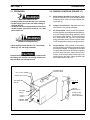
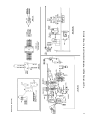
PISTON PLUG
PISTON
SPRING
FLOW SWITCH
H. With all input power disconnected, and wearing
proper eye and face protection, blow out the inside
of the PCM-500i using low-pressure dry com-
pressed air.
4.3 FLOW SWITCH (FIGURE 4-1)
When excessive contamination is found in the air, the
flow switch (FS) should be removed, disassembled and
cleaned as follows:
A. Ensure the system is shut down and there is no
trapped air under pressure in the piping.
B. Remove the piston plug.
C. Remove the spring (FS-4 only). Use care when
handling spring to prevent distortion.
D. Remove the piston.
E. Clean all parts with cleaning agent.
NOTE
Ensure cleaning agent does not contain solvents
which can degrade polysulfone. Warm water and
detergent is recommended for cleaning. Allow all
parts to dry thoroughly before reassembly.
Reassemble the flow switch in reverse order.
Figure 4-1. Disassembly / Assembly of Flow Switch

SECTION 5 TROUBLESHOOTING
20
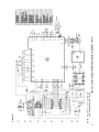
The cause of control malfunctions can be found by
referring to the sequence of operations and electrical
schematic diagram (Figure 5-1) and checking the vari-
ous components. A volt-ohmmeter will be necessary for
some of these checks.
Voltages in plasma cutting equipment are high
enough to cause serious injury or possibly death. Be
particularly careful around equipment when the cov-
ers are removed.
NOTE
Before checking voltages in the circuit, disconnect the
power from the high frequency generator to avoid dam-
aging your voltmeter.
5.1 TROUBLESHOOTING
ELECTRIC SHOCK CAN KILL! Be sure that all pri-
mary power to the machine has been externally
disconnected. Open the line (wall) disconnect switch
or circuit breaker before attempting inspection or
work inside of the power source.
Check the problem against the symptoms in the follow-
ing troubleshooting guide. The remedy may be quite
simple. If the cause cannot be quickly located, shut off
the input power, open up the unit, and perform a simple
visual inspection of all the components and wiring.
Check for secure terminal connections, loose or burned
wiring or components, bulged or leaking capacitors, or
any other sign of damage or discoloration.
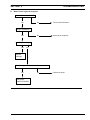
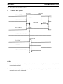
Depress torch switch. After 2 seconds, is high frequency present?
No
Repair/replace
high frequency
unit
Repair power
source
Yes
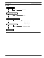
5.2 TROUBLESHOOTING GUIDE
A. Difficult Starting.
• Change electrode
• Change nozzle
• Check for good, clean connection of work lead to workpiece
• Check air pressure (65 - 75 psig)
• Check torch power cable for continuity

SECTION 5 TROUBLESHOOTING
21
B. No Air
Is air hose connected?
Yes No Connect
Is air adjusted to 65 - 75 psig?
Yes No Adjust
Does air come on with air check switch?
Yes No • No electrode in torch
• No valve pin in torch
• Replace electrode
Check continuity of torch switch • Replace valve pin
OK No Replace torch switch
Repair power source

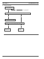
SECTION 5 TROUBLESHOOTING
22
C. Air does not shut off
Is air check switch OFF?
Yes No Turn switch OFF
Does arc start when nozzle contacts work without depressing torch switch?
Yes No
Check for short in torch switch
Does air flow even when PCM-500i power switch is OFF?
Yes No
Replace Repair power
solenoid valve source
Page is loading ...
Page is loading ...
Page is loading ...
Page is loading ...
Page is loading ...
Page is loading ...
Page is loading ...
Page is loading ...
Page is loading ...
Page is loading ...
Page is loading ...
Page is loading ...
Page is loading ...
Page is loading ...
Page is loading ...
Page is loading ...
Page is loading ...
Page is loading ...
-
 1
1
-
 2
2
-
 3
3
-
 4
4
-
 5
5
-
 6
6
-
 7
7
-
 8
8
-
 9
9
-
 10
10
-
 11
11
-
 12
12
-
 13
13
-
 14
14
-
 15
15
-
 16
16
-
 17
17
-
 18
18
-
 19
19
-
 20
20
-
 21
21
-
 22
22
-
 23
23
-
 24
24
-
 25
25
-
 26
26
-
 27
27
-
 28
28
-
 29
29
-
 30
30
-
 31
31
-
 32
32
-
 33
33
-
 34
34
-
 35
35
-
 36
36
-
 37
37
-
 38
38
-
 39
39
-
 40
40


ESAB PCM-500i Plasma Arc Cutting Packages User manual
- Category
- Welding System
- Type
- User manual
Ask a question and I''ll find the answer in the document
Finding information in a document is now easier with AI
Related papers
-
ESAB ABB Pulse Analog Interface Robotic Interface User manual
-
-
-
-
-
-
-
-
-
Other documents
-
KRAUS KCB-WS103BB Care & Cleaning Guide
-
Cebora 936 Plasma Prof 35 User manual
-
-
Miller ME030272V Owner's manual
-
-
Miller Electric BOBCAT 250 (ROBIN) User manual
-
Snap-On PLASMA30i User manual
-
Miller Electric Millermatic 350 User manual
-
-