Page is loading ...

PAGE 1 98194C (Rev. E - 6/08)
HDFF-EBP*A HDFF-BLEBP*A HDFF-BLREBP*A
IMPORTANT! INSTALLER PLEASE NOTE.
THE GROUNDING OF ELECTRICAL EQUIPMENT SUCH AS TELEPHONE, COMPUTERS, ETC. TO WATER LINES IS A COMMON PROCEDURE. THIS GROUNDING
MAY BE IN THE BUILDING OR MAY OCCUR AWAY FROM THE BUILDING. THIS GROUNDING CAN CAUSE ELECTRICAL FEEDBACK INTO A FOUNTAIN, CREATING
AN ELECTROLYSIS WHICH CAUSES A METALLIC TASTE OR AN INCREASE IN THE METAL CONTENT OF THE WATER. THIS CONDITION IS AVOIDABLE BY
USING THE PROPER MATERIALS AS INDICATED. ANY DRAIN FITTINGS PROVIDED BY THE INSTALLER SHOULD BE MADE OF PLASTIC TO ELECTRICALLY
ISOLATE THE FOUNTAIN FROM THE BUILDING PLUMBING SYSTEM.
IMPORTANT ! REMARQUE S’ADDRESSANT A L’INSTALLATEUR :
LA MISE A LA TERRE DES EQUIPEMENTS ELECTRIQUES TELS QUE LES TELEPHONES, ORDINATEURS, ETC. RELIES A DES CANALISATIONS D’EAU, CONSTITUE
UNE PROCEDURE COURANT. CETTE MISE A LA TERRE PEUT ETRE EFFECTUE AU SEIN DU BATIMENT OU LOIN DE CELUI-CI. CETTE MISE A LA TERRE PEUT
DANS CERTAINS CAS CAUSER UN RETOUR ELECTRIQUE DANS LA FONTAINE, QUI CREE ALORS UNE ELECTROLYSE ET DONNE UN GOUT DE METAL A L’EAU,
OU AUGMENTE LA CONTENANCE EN METAL DE L’EAU. POUR EVITER CETTE SITUATION, UTILISER LES MATERIAUX ADEQUATS QUI SONT INDIQUES. TOUT
LOGEMENT DE DRAINAGE FOURNI PAR L’INSTALLATEUR, DOIT ETRE EN PLASTIQUE, DE MANIERE A ISOLER LA FONTAINE A EAU DU SYSTEME DE PLOMBERIE
DU BATIMENT.
IMPORTANTE! INSTALADOR, TOME NOTA!
LA CONEXION DE UNA CORRIENTE ELECTRICA, TALES COMO EL TELEFONO, COMPUTADORAS, ETC. A LAS TUBERIAS DE AGUA ES UN PROCEDIMIENTO COMUN.
ESTA CONEXION PUEDE ESTAR DENTRO O FUERA DEL EDIFICIO. ESTA CONEXION PUEDE CAUSAR UNA REACCION DE REALIMENTACION ELECTRICA EN LA
FUENTE DE AGUA FRIA, CREANDO ELECTROLISIS, LO CUAL CAUSA UN SABOR METALICO O EL AUMENTO DEL CONTENIDO DE METAL EN EL AGUA. ESTAS
CONDICIONES PUEDEN EVITARSE USANDO LOS MATERIALES ADECUADOS, SEGUN SE INDICA. CUALQUIER MATERIAL DE DESAGÜE PROVISTO POR EL
INSTALADOR DEBE SER DE PLASTICO PARA AISLAR LA ELECTRICIDAD DE LA FUENTE DEL AGUA Y EL SISTEMA DE CAÑERÍA DEL SUMINISTRO DEL EDIFICIO.
IMPORTANT
TOUT ENTRETIEN DOIT ÊTRE EFFECTUÉ PAR UN REPRÉSENTANT AUTORISÉ
IMPORTANT
ALL SERVICE TO BE PERFORMED BY AN AUTHORIZED SERVICE PERSON
IMPORTANTE
TODO EL SERVICIO DEBERÁ SER EFECTUADO POR UNA PERSONA DE SERVICIO AUTORIZADA
Heavy Duty 14 Gauge Contour™ Series Barrier Free Fountains with Back Panels
Fuente de agua potable serie Contour Barrier Free
TM
, con paneles posteriores
de uso pesado de 14 calibre
Fontaines de série Contour™ sans barrière, robuste, acier calibre 14 avec panneaux arrières
Halsey Taylor Owners Manual
Manual del Propietario – Halsey Taylor
Halsey Taylor - Guide de l’utilisateur
INSTALLER
Halsey Taylor Fountains are among the easiest to install Fountains on the market today. To assure you install these models easily and correctly,
PLEASE READ THESE SIMPLE INSTRUCTIONS BEFORE STARTING THE INSTALLATION. CHECK YOUR INSTALLATION FOR COMPLIANCE
WITH PLUMBING, ELECTRICAL, AND OTHER APPLICABLE CODES. After installation, leave these instructions with the Fountain for future
reference.
INSTALADOR
Las fuentes de agua fría Halsey Taylor son consideradas en el mercado como unas de las más fáciles de instalar. Para asegurar una instalación
de estos modelos de una forma correcta y fácil, POR FAVOR LEA ESTAS SIMPLES INSTRUCCIONES ANTES DE COMENZAR LA INSTALA-
CION. REVISE SU INSTALACION PARA ASEGURARSE QUE CUMPLA CON LOS REQUISITOS DE NORMAS APLICABLES PARA PLOMERÍA,
ELECTRICIDAD Y OTROS CODIGOS. Luego de instalarla, guarde las instrucciones dentro de la fuente de agua fría para consultas futuras.
INSTALLATEUR :
A l’heure actuelle, les fontaines à eau Halsey Taylor sont parmi les plus faciles à installer du marché. Pour veiller à ce que l’installation se déroule
facilement et d’une manière correcte, NOUS VOUS PRIONS DE BIEN VOULOIR LIRE LES INSTRUCTIONS DE BASE AVANT DE DEBUTER
L’INSTALLATION. VERIFIER QUE L’INSTALLATION SOIT BIEN CONFORME AUX NORMES DE PLOMBERIE, D’ELECTRICITE, ET DES
AUTRES CODES NECESSAIRES. Après l’installation, conserver ces instructions près de la fontaine à eau, pour référence ultérieure.

PAGE 298194C (Rev. E - 6/08)
HDFF-EBP*A HDFF-BLEBP*A HDFF-BLREBP*A
INSTALLATION INSTRUCTIONS
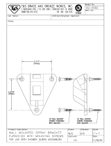
1. Wall should already be framed for the fountain using the
positioning dimensions shown in Figures 1,3,5,7,9 or 11.
Shown dimensions pertain to installation location (framing
must support up to 300 lbs. weight). These dimensions
are required for compliance with ANSI Standard A117.0.
2. Attach wall plate assembly to wall as shown in Figures 1,
5 or 9 using 5/16" x 2" long bolts and flat washers (not
provided). Tighten securely. (Fastener must match wall type,
i.e. lag screws for wood studs, bolts and anchors for
masonary construction.)
3. Install back panel. Place the upper edge of the panel
above hanger on the wall. Slide panel down until it engages
the hanger. Be sure back panel is firmly engaged before
releasing it.
4. Install rough-in plumbing as shown in Figures 1,3,5,7,9,
or 11. Waste line should extend a minimum of 2" (51mm)
thru the
back panel. Run supply water inlet line thru back panel.
Install a service stop (not provided). Turn on supply water
and flush thoroughly.
5. Remove bottom access panel from fountain basin and
save the screws. Install the fountain to the back panel using
(4) 5/16" x 3/4" long screws and washers (provided) thru
holes in back panel. Tighten securely.
6. Cut waste tube to required length using plumbing
hardware and a trap (not provided) as a guide. Install
hardware and trap. Tighten securely.
7. Make water supply connections from service stop to the
3/8" O.D. unplated copper tube coming out of the fountain
strainer (See Fig. 14). Turn on water supply and check for
leaks. Newly installed water supply line should be insulated
after leak check is completed. DO NOT SOLDER TUBES
INSERTED INTO THE STRAINER AS DAMAGE TO THE
O-RINGS MAY RESULT.
8. These products are designed to operate on 20-105 PSIG
supply line pressure. If inlet pressure is above 105 PSIG, a
pressure regulator must be installed in the supply line. Any
damage caused by reason of connecting these products to
supply line pressure lower than 20 PSIG or higher than 105
PSIG is not covered by warranty.
9. Check stream height from bubbler. Stream height is
factory set at 35 PSI. If supply pressure varies greatly from
this, adjust the screw on regulator (Item 19) by using a small
screwdriver through the small hole in the push button (Item
10), see fig. 21. Clockwise adjustment will raise stream
height and counter-clockwise adjustment will lower stream
height. For best adjustment stream should hit basin
approximately 6-1/2" (165mm) from bubbler.
10. Replace bottom access panel to fountain basin using
screws provided. Tighten securely.
INSTRUCCIONES DE INSTALACION
1. La pared donde va a instalarse la fuente de agua debe haber sido
marcada usando las dimensiones de posición según las ilustraciones
número 1,3,5,7,9 ó 11. Las dimensiones señaladas corresponden a la
localización de instalación (el marco debe soportar un peso de hasta
300 Lbs. (136 kg). Estas dimensiones son necesarias para cumplir con
los requisitos de los estándares ANSI A117.0.
2. Conecte el ensamblaje de la placa de pared a la pared de la manera
descrita en la Figura 1, 5 ó la Figura 9 usando pernos que miden 5/16"
x 2" y arandelas planas (no provistos). Apriete de un modo seguro. (Debe
concordar con el tipo de pared el sujetador usado, por ej., tornillos
rosca madera para tablillas de madera, pernos y anclajes para
construcción de mampostería.)
3. Instalación del panel posterior. Coloque el borde superior del panel
por encima del colgadero en la pared. Deslice el panel hacia abajo
hasta que se enganche con el colgador. Asegúrese que el panel
posterior esté enganchado antes de soltarlo.
4. Instale la tubería según los diseños 1,3,5,7,9, ó 11. La línea de
desagüe debe extenderse unas 2 pulgadas (51 mm) como mínimo a
través de la tapa de atrás. Pase la tubería del suministro de agua a
través de la tapa trasera. Instale una parada de servicio. (No está
incluido). Ponga a funcionar y deje correr el agua abundantemente.
5. Saque el panel inferior de acceso de la palangana de la fuente y
guarde los tornillos. Instale la fuente al panel posterior usando cuatro
(4) tornillos largos que miden 5/16" x 3/4" y las arandelas (provistos) a
través de los agujeros en el panel posterior. Apriete de un modo seguro.
6. Corte el tubo de desagüe con el largo deseado utilizando herramien
tas de plomería y la trampa (incluida) como guía. Instale las herramien
tas y la trampa. Apriete fuertemente.
7. Realice las conexiones al suministro de agua desde la parada de
servicio hasta el tubo no chapeado de cobre de diámetro exterior de
3/8" que sale del cedazo de la fuente (Ver Figura 14). Abra el suministro
de agua y verifique para fugas. Debe aislar la línea de suministro de
agua después de completar la verificación para fugas. NO DEBE
SOLDAR LOS TUBOS QUE ENTREN EN EL CEDAZO YA QUE
PUEDEN CAUSAR DAÑOS A LOS AROS TÓRICOS.
8. Estos productos están diseñados para trabajar con líneas de tubería
con una presión de 20-105 PSIG. Si la entrada de agua es mayor que
105 PSIG, un regulador de presión ha debe colocado en la tubería.
Cualquier daño que sea causado por la conexión de estos productos a
una presión de agua menor que 20 PSIG o mayor que 105 PSIG, no
será cubierta por la garantía.
9. Revise la altura del chorro de agua. La altura del chorro de agua ha
sido ajustado en su facricacion para una altura de 35 PSIG. Si la
presión del suministro varía mucho de esto, ajusta el tornillo en el
artículo de regulador 19 utilizando un destornillador pequeño por el
hoyo pequeño en el artículo del pulsador 10 (Vea la Fig. 21). Un giro
hacia la derecha aumentará la altura del chorro de agua, mientras que
un giro hacia la izquierda bajará el nivel del chorro del agua. Para
mejores resultados, la altura del chorro del agua debe ser aproximada
mente 6-1/2 pulgadas (165 mm) desde la base del grifo.
10. Vuelva a colocar la puerta de acceso de abajo usando los tornillos
provistos. Asegure firmemente.

PAGE 5 98194C (Rev. E - 6/08)
HDFF-EBP*A HDFF-BLEBP*A HDFF-BLREBP*A
* Adult ADA Requirement
Requisito ADA para adultos
Exigences adulte ADA
Orifice Height
Altura Del Orificio
Hauteur De L’Orifice
HDFF-EBP ROUGH-IN
DISEÑO HDFF-EBP
SCHEMA PLOMBERIE HDFF-EBP
Finished Floor
Suelo Terminado
Plancher Fine
FIG. 2
*
LEGEND
A = 1-1/4" Trap furnished
1-1/4” la trampa equipó
1-1/4” le piège a fourni

PAGE 7 98194C (Rev. E - 6/08)
HDFF-EBP*A HDFF-BLEBP*A HDFF-BLREBP*A
24 1/2"
622mm
20 3/8"
518mm
3 13/16"
97mm
12 1/8"
309mm
19 3/4"
502mm
27"
686mm
6 1/2"
165mm
35 3/8"
899mm
5/8"
16mm
18"
457mm
18 3/4"
476mm
FINISHED WALL
A
Orifice Height
Altura Del Orificio
Hauteur De L'Orifice
* Adult ADA Requirement
Requisito ADA para adultos
Exigences adulte ADA
HDFF-EBP ROUGH-IN
DISEÑO HDFF-EBP
SCHEMA PLOMBERIE HDFF-EBP
FIG. 4
LEGEND
A = 1-1/4" Trap furnished
1-1/4” la trampa equipó
1-1/4” le piège a fourni
Finished Floor
Suelo Terminado
Plancher Fine
*
MPW101 Mtg. Plt.
Ref. Separate
Installation Instructions
for details

PAGE 9 98194C (Rev. E - 6/08)
HDFF-EBP*A HDFF-BLEBP*A HDFF-BLREBP*A
HDFF-BLEBP ROUGH-IN
DISEÑO HDFF-BLEBP
SCHEMA PLOMBERIE HDFF-BLEBP
Orifice Height
Altura Del Orificio
Hauteur De L’Orifice
Finished Floor
Suelo Terminado
Plancher Fine
Orifice Height
Altura Del Orificio
Hauteur De L’Orifice
FIG. 6
*
* Adult ADA Requirement
Requisito ADA para adultos
Exigences adulte ADA
LEGEND
A = 1-1/4" Trap furnished
1-1/4” la trampa equipó
1-1/4” le piège a fourni

PAGE 11 98194C (Rev. E - 6/08)
HDFF-EBP*A HDFF-BLEBP*A HDFF-BLREBP*A
FINISHED WALL
27"
686mm
6 1/2"
165mm
24 1/2"
622mm
20 3/8"
518mm
33"
838mm
3 13/16"
97mm
12 1/8"
309mm
6 5/8"
168mm
38 1/2"
978mm
5/8"
16mm
18"
457mm
18 3/4"
476mm
35 3/8"
899mm
41 3/8"
1051mm
A
Orifice Height
Altura Del Orificio
Hauteur De L'Orifice
Orifice Height
Altura Del Orificio
Hauteur De L'Orifice
HDFF-BLEBP ROUGH-IN
DISEÑO HDFF-BLEBP
SCHEMA PLOMBERIE HDFF-BLEBP
FIG. 8
* Adult ADA Requirement
Requisito ADA para adultos
Exigences adulte ADA
LEGEND
A = 1-1/4" Trap furnished
1-1/4” la trampa equipó
1-1/4” le piège a fourni
Finished Floor
Suelo Terminado
Plancher Fine
*
MPW200 Mtg. Plt.
Ref. Separate
Installation
Instructions
for details

PAGE 13 98194C (Rev. E - 6/08)
HDFF-EBP*A HDFF-BLEBP*A HDFF-BLREBP*A
HDFF-BLREBP ROUGH-IN
DISEÑO HDFF-BLREBP
SCHEMA PLOMBERIE HDFF-BLREBP
FIG. 10
* Adult ADA Requirement
Requisito ADA para adultos
Exigences adulte ADA
LEGEND
A = 1-1/4" Trap furnished
1-1/4” la trampa equipó
1-1/4” le piège a fourni
Finished Floor
Suelo Terminado
Plancher Fine
Orifice Height
Altura Del Orificio
Hauteur De L’Orifice
Orifice Height
Altura Del Orificio
Hauteur De L’Orifice
*

PAGE 15 98194C (Rev. E - 6/08)
HDFF-EBP*A HDFF-BLEBP*A HDFF-BLREBP*A
27"
686mm
6 1/2"
165mm
33"
838mm
3 13/16"
97mm
12 1/8"
309mm
6 5/8"
168mm
38 1/2"
978mm
A
5/8"
16mm
18"
457mm
18 3/4"
476mm
35 3/8"
899mm
41 3/8"
1051mm
24 1/2"
622mm
20 3/8"
518mm
FINISHED WALL
Orifice Height
Altura Del Orificio
Hauteur De L'Orifice
Orifice Height
Altura Del Orificio
Hauteur De L'Orifice
HDFF-BLREBP ROUGH-IN
DISEÑO HDFF-BLREBP
SCHEMA PLOMBERIE HDFF-BLREBP
FIG. 12
* Adult ADA Requirement
Requisito ADA para adultos
Exigences adulte ADA
LEGEND
A = 1-1/4" Trap furnished
1-1/4” la trampa equipó
1-1/4” le piège a fourni
Finished Floor
Suelo Terminado
Plancher Fine
*
MPW200 Mtg. Plt.
Ref. Separate
Installation
Instructions
for details

PAGE 1698194C (Rev. E - 6/08)
HDFF-EBP*A HDFF-BLEBP*A HDFF-BLREBP*A
1/4" O.D. TUBE WATER INLET TO COOLER
ENTRADA DE AGUA DE TUBO DE 1/4" DE
DIÁMETRO EXTERNO AL ENFRIADOR
TUBE DE D.E. 1/4" POUR ENTRÉE DE L’EAU DANS
LE REFROIDISSEUR
SERVICE STOP
(NOT FURNISHED)
VÁLVULA DE PARADA
(NO ES PROPORCIONADA)
BLOC D’ARRÊT
(NON FOURNI)
NOTE: WATER FLOW DIRECTION
NOTA: DIRECCIÓN DEL FLUJO DE AGUA
NOTE : L’EAU COULE DANS CETTE
DIRECTION
BUILDING WATER INLET
ENTRADA DE AGUA DEL EDIFICIO
ENTRÉE DE L’EAU DE L’ÉDIFICE
3/8" O.D. UNPLATED COPPER TUBE CONNECT COLD WATER SUPPLY
CONEXIÓN DEL TUBO DE COBRE SIN CHAPAR DE 3/8" DE DIÁM. EXT.
SUMINISTRO DE AGUA FRÍA
LE TUBE EN CUIVRE NON PLAQUÉ DE 3/8 PO. (9,5 mm) D.E. CONNECTE
L'ALIMENTATION EN EAU FROIDE.
AB C
Simply Push In Tube To Attach
Simplemente Empuje El Tubo Para
Trabar
Poussez Simplement Le Tube Pour
Fixer En Place.
Tube Is Secured In Position
El Tubo Está Asegurado En Su
Posición
Le Tube Est Fixé Solidement En
Place
Push In Collet To Release Tube
Presione El Anillo-Guía Para Soltar
El Tubo
Poussez La Bague De Serrage
Pour Dégager Le Tube
Pushing Tube In Before Pulling
It Out Helps To Release Tube.
Presionar El Tubo Antes De Tirar
De Él Ayuda A Soltar El Tubo.
On Peut Retirer Le Tube Plus
Facilement En Le Poussant Vers
L’intérieur D’abord Puis En Le
Retirant.
OPERATION OF QUICK CONNECT FITTINGS
FUNCIONAMIENTO DE LOS ACCESORIOS DE CONEXIÓN RÁPIDA
FONCTIONNEMENT DES RACCORDS RAPIDES
1
2
3
NOTE:
LORSQUE VOUS INSTALLEZ UN NOUVEAU
BARBOTEUR ET SOCLE, RESSERREZ L’ÉCROU
(ARTICLE 2) SEULEMENT SUFFISAMMENT POUR
GARDER LES PIÈCES BIEN EN PLACE.
NE PAS TROP SERRER.
NOTE:
WHEN INSTALLING REPLACEMENT BUBBLER AND
PEDESTAL, TIGHTEN NUT (ITEM 2) ONLY TO HOLD
PARTS SNUG IN POSITION.
DO NOT OVER TIGHTEN.
NOTA:
CUANDO SE INSTALE EL BORBOTEADOR DE
REPUESTO Y EL PEDESTAL, APRIETE LA TUERCA
(ARTICULO 2) SOLAMENTE PARA SOSTENER LAS
PIEZAS EN SU POSICIÓN.
NO APRIETE EMASIADO.
FIG. 15
FIG. 14
FIG. 13

PAGE 17 98194C (Rev. E - 6/08)
HDFF-EBP*A HDFF-BLEBP*A HDFF-BLREBP*A
FIG. 18
5
4
FIG. 16
5
4
HDFF-EBP
HDFF-BLEBP
FIG. 20
SEE FIG. 15
VEA LA FIG. 15
VOIR FIG. 15
6, 20
17
16
16
SEE FIG. 21
VEA LA FIG. 21
VOIR FIG. 21
5
4
FIG. 19
HDFF-BLREBP
FIG. 17
26
Installing Back Panel: When installing back panel assy.
(Item 26) with MPW (Mounting Plate), attach channel braces
as shown above. Remove the protective backing from the tape
installed on the braces. Line up the corresponding holes in the
braces and back panel and press firmly in place.
HDFF-BLEBP

PAGE 1898194C (Rev. E - 6/08)
HDFF-EBP*A HDFF-BLEBP*A HDFF-BLREBP*A
ITEM NO.
PART NO.
1
2
3
4
5
6
7
8
9
10
11
12
13
14
15
16
17
18
19
20
21
22
23
24
25
26
NS
NS
NS
Gasket
Bubbler Nipple
Bubbler
Mounting Plate Assy. HDFF-EBP
Mounting Plate Assy. HDFF-BLEBP
Mounting Plate Assy. HDFF-BLREBP
Back Panel HDFF-EBP
Back Panel HDFF-BLEBP
Back Panel HDFF-BLREBP
Screw - 5/16-18 x 3/4
Regulator Retaining Nut
Regulator Mounting Bracket
Hex Nut
Push Button
Regulator Mounting Nut
Push Button Sleeve
Drain Plug
Drain Assy.
Regulator Holder
Poly Tubing - (Cut To Length)
In - Line Strainer
Drain Gasket
Regulator
Flat Washer
Pinned Torx Screw 1/4-20 x .75"
Cap Screw
Bottom Cover
Basin
Edge TriM
Back Panel Assy. HDFF-EBP
Back Panel Assy. HDFF-BLEBP
Back Panel Assy. HDFF-BLREBP
Hanger Bracket HDFF-EBP
Hanger Bracket HDFF-BL(R)EBP
Bit - Pinned Torx T-25
DESCRIPTION
Junta
Boquilla-Borboteador
Grifo
Ensamblaje de Montaje de la Placa HDFF-EBP
Ensamblaje de Montaje de la Placa HDFF-BLEBP
Ensamblaje de Montaje de la Placa HDFF-BLREBP
Panel Posterior HDFF-EBP
Panel Posterior HDFF-BLEBP
Panel Posterior HDFF-BLREBP
Tornillo - 5/16-18 x 3/4
Tuerca de Retención
Fijador de Montaje del Reguladora
Tuerca Hexagonal
Botón pulsador
Tuerca Reguladora de Montaje
Cuerpo del botón pulsador
Tapón del Desagüe
Conexión Desagüe
Sujetador Regulado
Tubo de polietileno (corte según largo deseado)
Filtro Interior
Junta de Desagüe
Regulador
Arandela Plana
El Tornillo de Pinned Torx # 1/4-20 x 0,75
Conjunto de Tornillos
Tapa Inferior
Vasija
Ajuste Del Borde
Ensamblaje de Posterior de la Panel HDFF-EBP
Ensamblaje de Posterior de la Panel HDFF-BLEBP
Ensamblaje de Posterior de la Panel HDFF-BLREBP
Fijador de suspensión HDFF-EBP
Fijador de suspensión HDFF-BL(R)EBP
Pinned de pedacito Torx T-25
Joint
Mamelon - barboteur
Tube à bulles
Ensemble de la plaque de montage HDFF-EBP
Ensemble de la plaque de montage HDFF-BLEBP
Ensemble de la plaque de montage HDFF-BLREBP
Panneau arrière HDFF-EBP
Panneau arrière HDFF-BLEBP
Panneau arrière HDFF-BLREBP
Vis - 5/16-18 x 3/4
Écrou de rétention du régulateur
Support de montage du régleur
Ecrou Hex
Bouton pression
Écrou de montage de régulateur
Manchon du bouton pression
Bouchon de vidange
Prise d’écoulement
Support de maintien du régulateur
Tube poly (coupé à la bonne longueur)
Egouttoir du conduit interne Régulateur
Joint d’écoulement
Régulateur
Rondelle plate
Vis Torx à clavette 6,3mm – 20 x 2mm
Vis de fixation n
Couvercle du fond
Evier
Équilibre De Bord
Ensemble de la panneau de arrière HDFF-EBP
Ensemble de la panneau de arrière HDFF-BLEBP
Ensemble de la panneau de arrière HDFF-BL(R)EBP
Support de suspension HDFF-EBP
Support de suspension HDFF-BL(R)EBP
Torx à clavettes bit T-25
PARTS LIST/LISTA DE PIEZAS/LISTE DE PIÈCES
DESCRIPCIÓN DESCRIPTION
100322740560
15009C
98118C
28170C
28159C
28171C
28625C
28626C
28659C
111577243890
15005C
28823C
40045C
45662C
45736C
45737C
45728C
LK464
50986C
56092C
55996C
50074C
61313C
75541C
75570C
75672C
28630C
28627C
56280C
28840C
28841C
28842C
27089C
27090C
75520C
FIG. 21
15
13
3
24
14
18
8
21
23
9
7
19
12
10
22 1
11
SEE FIG. 16,17,18, or 19
VEA LA FIG. 16,17,18, ó 19
VOIR FIG. 16,17,18, ou 19
2
FOR PARTS, CONTACT YOUR LOCAL DISTRIBUTOR OR VISIT OUR WEBSITE WWW.HALSEYTAYLOR.COM
PRINTED IN U.S.A.
2222 CAMDEN COURT
OAK BROOK, IL 60523
630.574.3500
25
/