
Betriebsanleitung / Operating Instructions
Instructions de Service / Manual de instrucciones
Manuale d’uso e manutenzione
PILOT WA 900 / PILOT WA 905
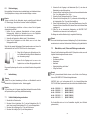
Modelle / Models / Modèles / Modelos / Modelli
Automatische Spritzpistolen / Automatic Spray Guns
Pistolets de Pulvérisation Automatiques / Pistolas de Pulverización Automáticas
Pistole a spruzzo automatiche

32
1
2
3
4
5
7
19
20
21
22
23
24
25
26
27
8
9
10
11
12
13
14
15
31
30
17
18
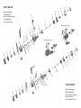
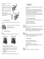
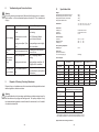
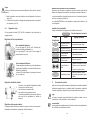
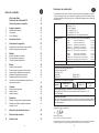
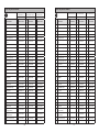
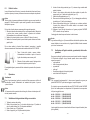
PILOT WA 905
Ohne Innensteuerung
Without internal control
Sans commande intérieure
Sin control interno
Senza comando interno
1
2
3
4
5
16
19
20
21
22
23
27
24
25
26
8
9
10
11
12
13
14
15
31
30
17
18
28
29
7
PILOT WA 900
Mit Innensteuerung
With internal control
Avec commande intérieure
Con control interno
Con comando interno
9
10
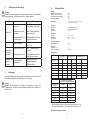
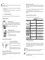
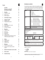
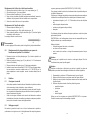
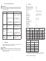
Adapterplatte MA hinten
1
8
4
6
7
3
5
2
1
8
8
4
6
7
3
5
2
10
9
11
Adapterplatte MA seitlich
Page is loading ...
Page is loading ...
Page is loading ...
Page is loading ...
Page is loading ...
Page is loading ...
Page is loading ...
Page is loading ...
Page is loading ...
Page is loading ...
Page is loading ...
Page is loading ...

2928
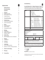
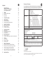
Contents
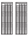
Exploded Drawing 2
Declaration of CE-Conformity 29
List of Replacement Parts 30
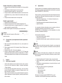
1 General 36
1.1 Identification of Model Version 36
1.2 Normal Use 36
1.3 Improper Use 37
2 Technical Description 37
3 Safety Warnings 38
3.1 Safety Warting Symbols 38
3.2 Generally Applicable Safety Precautions 39
4 Assembly / Installation 39
4.1 Radial or circulation method 39
4.2 Mounting of Spray Gun 40
4.3 Connection of Input Lines 40
5 Operational Handling 41
5.1 Safety Warnings 41
5.2 Starting/Stopping Requirements 41
5.3 Spray Pattern Test 41
5.4 Spray Pattern Adjustments 42
5.5 Retooling of Spray Gun 43
5.6 Conversion of adapter plate from radial to circulation method 44
6 Cleaning 44
6.1 Safety Warnings 44
6.2 Cleaning - Complete 44
6.3 Cleaning - Routine 46
7 Repairs / Replacements 46
7.1 Replacement of defective Needle Seal Packings 46
7.2 Replacement of Nozzles, Needles, Springs and Seals 47
8 Trouble shooting and Corrective Action 48
9 Disposal of Cleaning / Servicing Substances 48
10 Specification Data 49
Declaration of Conformity
We, the manufacturers of the equipment, hereby declare under our sole responsibility that the
product(s) described below conform to the essential safety requirements. This declaration will be
rendered invalid if any changes are made to the equipment without prior consultation with us.
Manufacturer WALTHER Spritz- und Lackiersysteme GmbH
Kärntner Str. 18 - 30
D - 42327 Wuppertal
Tel.: +49(0)202 / 787 - 0
Fax: +49(0)202 / 787 - 2217
www.walther-pilot.de • e-mail: [email protected]
Type Designation
Automatic Spray Guns PILOT WA 900-Models
WA 900 (Standard with internal control) V 21 900
WA 905 (Standard without internal control) V 21 905
WA 920-HVLP (Low pressure with internal control) V 21 920
WA 925-HVLP (Low pressure without internal control) V 21 925
WA 940-HVLP
PLUS
(Mediem pressure with internal control) V 21 940
WA 945-HVLP
PLUS
(Mediem pressure without internal control) V 21 945
WA 903-K (Standard adhesive with internal control) V 21 903
WA 908-K (Standard adhesive without internal control) V 21 908
WA 923-HVLP-K (Low pressure adhesive with internal control) V 21 923
WA 928-HVLP-K (Low pressure adhesive without internal control) V 21 928
Intended purpose Processing of sprayable media
Applied Standards and Directives
EU-Mechanical Engineering Directives 2006/42/EC
2014/34/EU (ATEX Directives)
DIN EN ISO 12100
DIN EN 1953 DIN EN 13463-1
DIN EN 1127-1 DIN EN 13463-5
Specification according 2014/34/EU
Category 2 Part marking
II 2 G c T 5
Tech.File,Ref.:
2416
Authorized with the compilation of the technical file:
Nico Kowalski, WALTHER Spritz- und Lackiersysteme GmbH, Kärntner Str. 18 - 30
D- 42327 Wuppertal
Special remarks :
The named product is intended for installation in other equipment. Commissioning is prohibited
until such time as the end product has been proved to conform to the provision of the Directives
2006/42/EC.
Wuppertal, the 2nd of November 2016
Name: Torsten Bröker
Position: Manager, Design and Development
This Declaration does not give assurance of properties in the sense of product liability. The safety instructions
provided in the product documentation must be observed at all times.
p.p.

3130
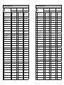
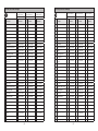
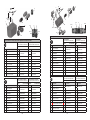
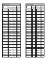
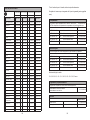
Listing of Replacement Parts:
WA 900
(with internal control)
WA 905
(without internal control)
WA 920 HVLP
(with internal control)
V 21 900 V 21 905 V 21 920
Item.
Description
piece.
Parts No.
piece
Parts No.
piece
Parts No.
1 Retaining Ring compl. 1 V 20 700 05 000 1 V 20 700 05 000 1 V 20 700 05 000
2 Air Cap* 1 V 10 700 35 xx8* 1 V 10 700 35 xx8* 1 V 10 700 37 xxx*
3 Material nozzle* 1 V 10 700 40 xx3* 1 V 10 700 40 xx3* 1 V 10 700 40 xx3*
4 Air distribution ring 1 V 21 900 14 000 1 V 21 900 14 000 1 V 21 900 14 100
5 Hexagon socket screw 4 V 20 700 13 003 4 V 20 700 13 003 4 V 20 700 13 003
7 Front Body compl. 1 V 21 900 02 103 1 V 21 900 02 103 1 V 21 900 02 103
8 O-Ring 2 V 09 102 21 009 2 V 09 102 21 009 2 V 09 102 21 009
9
Needle seal Packing
compl.
1 V 09 001 74 000 1 V 09 001 74 000 1 V 09 001 74 000
10 Washer 1 V 21 900 12 003 1 V 21 900 12 003 1 V 21 900 12 003
11 Packing Spring 1 V 20 510 12 003 1 V 20 510 12 003 1 V 20 510 12 003
12 Packing Screw 1 V 20 510 11 003 1 V 20 510 11 003 1 V 20 510 11 003
13 Pin to fix air cap 1 V 20 700 02 303 1 V 20 700 02 303 1 V 20 700 02 303
14 Locking spring 1 V 20 700 02 403 1 V 20 700 02 403 1 V 20 700 02 403
15 Set screw 1 V 11 530 01 010 1 V 11 530 01 010 1 V 11 530 01 010
16 Plug 1 2325502 - - 1 2325502
17 Packing Screw 1 V 22 650 43 100 1 V 22 650 43 100 1 V 22 650 43 100
18 Lip seal 1 V 09 220 30 000 1 V 09 220 30 000 1 V 09 220 30 000
19 Piston Casing 1 V 21 900 01 000 1 V 21 905 01 000 1 V 21 900 01 000
20 Piston kompl. 1 V 21 900 09 000 1 V 21 905 07 000 1 V 21 900 09 000
21 Material Needle compl.* 1 V 21 900 05 xx3* 1 V 21 900 05 xx3* 1 V 21 900 05 xx3*
22 Piston Spring 1 V 20 606 11 100 1 V 20 606 11 100 1 V 20 606 11 100
23 Threaded Ring compl. 1 V 21 900 10 000 1 V 21 900 10 000 1 V 21 900 10 000
24 Needle Spring 1 V 20 510 29 003 1 V 20 510 29 003 1 V 20 510 29 003
25 Needle spring washer 1 V 21 900 11 000 1 V 21 900 11 000 1 V 21 900 11 000
26 Cap compl. 1 V 21 900 13 000 1 V 21 900 13 000 1 V 21 900 13 000
27 Drawbar compl. 1 V 20 510 34 000 1 V 20 510 34 000 1 V 20 510 34 000
28
'A'-adjustment compl.
(atomizing air)
1 V 21 900 25 000 - - 1 V 21 900 25 000
29
'F'-adjustment compl.
(fan air)
1 V 21 900 24 000 - - 1 V 21 900 24 000
30 Sealing pin compl. 1 V 21 900 08 000 1 V 21 900 08 000 1 V 21 900 08 000
31 Socket head cap screw 2 V 20 810 14 203 2 V 20 810 14 203 2 V 20 810 14 203
Listing of Replacement Parts:
WA 925 HVLP
(without internal control)
WA 940 HVLP
Plus
(with internal control)
WA 945 HVLP
Plus
(without internal control)
V 21 925 V 21 940 V 21 945
Item.
Description
piece.
Parts No.
piece
Parts No.
piece
Parts No.
1 Retaining Ring compl. 1 V 20 700 05 000 1 V 20 700 05 000 1 V 20 700 05 000
2 Air Cap* 1 V 10 700 37 xxx* 1 V 10 700 36 xxx* 1 V 10 700 36 xxx*
3 Material nozzle* 1 V 10 700 40 xx3* 1 V 10 700 40 xx3* 1 V 10 700 40 xx3*
4 Air distribution ring 1 V 21 900 14 100 1 V 21 900 14 100 1 V 21 900 14 100
5 Hexagon socket screw 4 V 20 700 13 003 4 V 20 700 13 003 4 V 20 700 13 003
7 Front Body compl. 1 V 21 900 02 103 1 V 21 900 02 103 1 V 21 900 02 103
8 O-Ring 2 V 09 102 21 009 2 V 09 102 21 009 2 V 09 102 21 009
9
Needle seal Packing
compl.
1 V 09 001 74 000 1 V 09 001 74 000 1 V 09 001 74 000
10 Washer 1 V 21 900 12 003 1 V 21 900 12 003 1 V 21 900 12 003
11 Packing Spring 1 V 20 510 12 003 1 V 20 510 12 003 1 V 20 510 12 003
12 Packing Screw 1 V 20 510 11 003 1 V 20 510 11 003 1 V 20 510 11 003
13 Pin to fix air cap 1 V 20 700 02 303 1 V 20 700 02 303 1 V 20 700 02 303
14 Locking spring 1 V 20 700 02 403 1 V 20 700 02 403 1 V 20 700 02 403
15 Set screw 1 V 11 530 01 010 1 V 11 530 01 010 1 V 11 530 01 010
16 Plug - - 1 2325502 - -
17 Packing Screw 1 V 22 650 43 100 1 V 22 650 43 100 1 V 22 650 43 100
18 Lip seal 1 V 09 220 30 000 1 V 09 220 30 000 1 V 09 220 30 000
19 Piston Casing 1 V 21 905 01 000 1 V 21 900 01 000 1 V 21 905 01 000
20 Piston kompl. 1 V 21 905 07 000 1 V 21 900 09 000 1 V 21 905 07 000
21 Material Needle compl.* 1 V 21 900 05 xx3* 1 V 21 900 05 xx3* 1 V 21 900 05 xx3*
22 Piston Spring 1 V 20 606 11 100 1 V 20 606 11 100 1 V 20 606 11 100
23 Threaded Ring compl. 1 V 21 900 10 000 1 V 21 900 10 000 1 V 21 900 10 000
24 Needle Spring 1 V 20 510 29 003 1 V 20 510 29 003 1 V 20 510 29 003
25 Needle spring washer 1 V 21 900 11 000 1 V 21 900 11 000 1 V 21 900 11 000
26 Cap compl. 1 V 21 900 13 000 1 V 21 900 13 000 1 V 21 900 13 000
27 Drawbar compl. 1 V 20 510 34 000 1 V 20 510 34 000 1 V 20 510 34 000
28
‘A‘-adjustment compl.
(atomizing air)
- - 1 V 21 900 25 000 - -
29
‘F‘-adjustment compl.
(fan air)
- - 1 V 21 900 24 000 - -
30 Sealing pin compl. 1 V 21 900 08 000 1 V 21 900 08 000 1 V 21 900 08 000
31 Socket head cap screw 2 V 20 810 14 203 2 V 20 810 14 203 2 V 20 810 14 203

3332
* Please quote the required size(s) when placing an order for replacement parts.
It is recommended to keep in stock all BOLD-faced parts (fast wearing parts).
Repair kit
WALTHER PILOT repair kits are available for PILOT WA 900 - WA 945 HVLP
PLUS
spray guns
including all wearing parts.
Parts-No.
PILOT WA 900 / 905 Standard-version V 16 209 00 XX3
PILOT WA 920 / 925 HVLP / Low pressure-version V 16 209 20 XX3
PILOT WA 940 / 945 HVLP
PLUS
/ Medium pressure-version V 16 209 40 XX3
PILOT WA 903 / 908 Standard adhesive-version V 16 219 03 XX3
PILOT WA 923 / 928 HVLP / Low pressure-adhesive-version V 16 219 23 XX3
Nozzle set
Nozzle sets consist of air cap, material nozzle and material needle.
Parts-No.
PILOT WA 900 / 905 Standard-version V 15 209 00 XX3
PILOT WA 920 / 925 HVLP / Low pressure-version V 15 209 20 XX3
PILOT WA 940 / 945 HVLP
PLUS
/ Medium pressure-version V 15 209 40 XX3
PILOT WA 903 / 908 Standard adhesive-version V 15 219 03 XX3
PILOT WA 923 / 928 HVLP / Low pressure-adhesive-version V 15 219 23 XX3
Nozzle sizes optional:
0,3 ▪ 0,5 ▪ 0,8 ▪ 1,0 ▪ 1,2 ▪ 1,5 ▪ 1,8 ▪ 2,0 ▪ 2,2 ▪ 2,5 ▪ 3,0 ▪ 3,5 mm ø
Seal set for Adaptor plate
The seal set contains all item numbers marked with ♦.
Adaptor plate Aluminium, nickel coated / Adaptor plate stainless steel V 17 219 00 000
Accessories
Parts-No.
Gun holder V 21 900 21 000
WALTHER PILOT gun grease Pads 8 - 10 g V 00 000 00 001
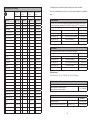
Listing of Replacement Parts:
WA 903-adhesive
(with internal control)
WA 908-adhesive
(without internal control)
WA 923 HVLP-adhesive
(with internal control)
WA 928 HVLP-adhesive
(without internal control)
V 21 903 V 21 908 V 21 923 V 21 928
Item
Description
piece
Parts No.
piece
Parts No.
piece
Parts No.
piece
Parts No.
1
Retaining Ring compl.
1 V 20 700 05 000 1 V 20 700 05 000 1 V 20 700 05 000 1 V 20 700 05 000
2
Air Cap *
1 V 10 711 35 xx5* 1 V 10 711 35 xx5* 1 V 10 711 35 xx5* 1 V 10 711 35 xx5*
3
Material nozzle*
1 V 10 711 40 xx3* 1 V 10 711 40 xx3* 1 V 10 711 40 xx3* 1 V 10 711 40 xx3*
4
Air distribution ring
1 V 21 900 14 000 1 V 21 900 14 000 1 V 21 900 14 100 1 V 21 900 14 100
5
Hexagon socket screw
4 V 20 700 13 003 4 V 20 700 13 003 4 V 20 700 13 003 4 V 20 700 13 003
7
Front Body compl.
1 V 21 900 02 103 1 V 21 900 02 103 1 V 21 900 02 103 1 V 21 900 02 103
8
O-Ring
2 V 09 102 21 009 2 V 09 102 21 009 2 V 09 102 21 009 2 V 09 102 21 009
9
Needle seal Packing
compl.
1 V 09 001 74 000 1 V 09 001 74 000 1 V 09 001 74 000 1 V 09 001 74 000
10
Washer
1 V 21 900 12 003 1 V 21 900 12 003 1 V 21 900 12 003 1 V 21 900 12 003
11
Packing Spring
1 V 20 510 12 003 1 V 20 510 12 003 1 V 20 510 12 003 1 V 20 510 12 003
12
Packing Screw
1 V 20 510 11 003 1 V 20 510 11 003 1 V 20 510 11 003 1 V 20 510 11 003
13
Pin to fix air cap
1 V 20 700 02 303 1 V 20 700 02 303 1 V 20 700 02 303 1 V 20 700 02 303
14
Locking spring
1 V 20 700 02 403 1 V 20 700 02 403 1 V 20 700 02 403 1 V 20 700 02 403
15
Set screw
1 V 11 530 01 010 1 V 11 530 01 010 1 V 11 530 01 010 1 V 11 530 01 010
16
Plug
1 2325502 - - 1 2325502 - -
17
Packing Screw
1 V 22 650 43 100 1 V 22 650 43 100 1 V 22 650 43 100 1 V 22 650 43 100
18
Lip seal
1 V 09 220 30 000 1 V 09 220 30 000 1 V 09 220 30 000 1 V 09 220 30 000
19
Piston Casing
1 V 21 900 01 000 1 V 21 905 01 000 1 V 21 900 01 000 1 V 21 905 01 000
20
Piston kompl.
1 V 21 900 09 000 1 V 21 905 07 000 1 V 21 900 09 000 1 V 21 905 07 000
21
Material Needle compl.*
1 V 21 903 05 xx3* 1 V 21 903 05 xx3* 1 V 21 903 05 xx3* 1 V 21 903 05 xx3*
22
Piston Spring
1 V 20 606 11 100 1 V 20 606 11 100 1 V 20 606 11 100 1 V 20 606 11 100
23
Threaded Ring compl.
1 V 21 900 10 000 1 V 21 900 10 000 1 V 21 900 10 000 1 V 21 900 10 000
24
Needle Spring
1 V 20 510 29 003 1 V 20 510 29 003 1 V 20 510 29 003 1 V 20 510 29 003
25
Needle spring washer
1 V 21 900 11 000 1 V 21 900 11 000 1 V 21 900 11 000 1 V 21 900 11 000
26
Cap compl.
1 V 21 900 13 000 1 V 21 900 13 000 1 V 21 900 13 000 1 V 21 900 13 000
27
Drawbar compl.
1 V 20 510 34 000 1 V 20 510 34 000 1 V 20 510 34 000 1 V 20 510 34 000
28
'A'-adjustment compl.
(atomizing air)
1 V 21 900 25 000 - - 1 V 21 900 25 000 - -
29
'F'-adjustment compl.
(fan air)
1 V 21 900 24 000 - - 1 V 21 900 24 000 - -
30
Sealing pin compl.
1 V 21 900 08 000 1 V 21 900 08 000 1 V 21 900 08 000 1 V 21 900 08 000
31
Socket head cap screw
2 V 20 810 14 203 2 V 20 810 14 203 2 V 20 810 14 203 2 V 20 810 14 203

3534
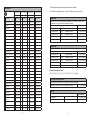
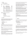
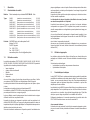
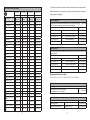
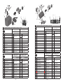
Replacement Parts for Adaptor plate Aluminium, nickel coated
Adaptor plate
Material connection rear
Adaptor plate
Material connection rear
WA 900 V 21 900 03 000 WA 905 V 21 905 04 000
Item Description piece Parts No. piece Parts No.
1 Adaptor plate 1
V 21 900 03 200
1
V 21 900 03 200
2 Cylindrical pin 2 2
3 O-Ring 2 V 09 103 66 000 ♦ 2 V 09 103 66 000 ♦
4 O-Ring 3 V 09 102 21 009 ♦ 3 V 09 102 21 009 ♦
5 O-Ring 1 V 09 104 11 009 ♦ 1 V 09 104 11 009 ♦
6 Push-in-fitting 1 V 66 101 53 013 1 V 66 101 53 013
7 Push-in-fitting 1 V 66 101 53 015 2 V 66 101 53 015
8 Double nipple 1 V 00 101 01 003 1 V 00 101 01 003
9 Plug 1 V 66 100 03 568 - -
10 Blanking plug 1 V 20 540 40 003 1 V 20 540 40 003
Adaptor plate circulation
Material connection rear
Adaptor plate circulation
Material connection rear
WA 900 V 21 900 03 UML WA 905 V 21 905 04 UML
Item Description piece Parts No. piece Parts No.
1 Adaptor plate 1
V 21 900 03 200
1
V 21 900 03 200
2 Cylindrical pin 2 2
3 O-Ring 2 V 09 103 66 000 ♦ 2 V 09 103 66 000 ♦
4 O-Ring 3 V 09 102 21 009 ♦ 3 V 09 102 21 009 ♦
5 O-Ring 1 V 09 104 11 009 ♦ 1 V 09 104 11 009 ♦
6 Push-in-fitting 1 V 66 101 53 013 1 V 66 101 53 013
7 Push-in-fitting 1 V 66 101 53 015 2 V 66 101 53 015
8 Double nipple 2 V 00 101 01 003 2 V 00 101 01 003
9 Plug 1 V 66 100 03 568 - -
10 Blanking plug - - - -
9
10
7 / 9 7
6
8 / 10
8 / 10
2
5
4
3
1
7
6
8
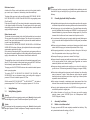
Replacement Parts for Adaptor plate stainless steel
Adaptor plate
Material connection lateral
Adaptor plate
Material connection lateral
WA 900 V 21 900 04 003 WA 905 V 21 905 03 003
Item Description piece Parts No. piece Parts No.
1 Adaptor plate 1
V 21 900 04 203
1
V 21 900 04 203
2 Cylindrical pin 2 2
3 O-Ring 2 V 09 103 66 000 ♦ 2 V 09 103 66 000 ♦
4 O-Ring 3 V 09 102 21 009 ♦ 3 V 09 102 21 009 ♦
5 O-Ring 1 V 09 104 11 009 ♦ 1 V 09 104 11 009 ♦
6 Push-in-fitting 1 V 66 101 53 013 1 V 66 101 53 013
7 Push-in-fitting 1 V 66 101 53 015 2 V 66 101 53 015
8 Material connection 90° 1 V 21 900 20 003 1 V 21 900 20 003
9 Plug 1 V 66 100 03 568 - -
10 Blanking plug 1 V 20 540 40 003 1 V 20 540 40 003
11 Nut 1 V 21 900 16 000 1 V 21 900 16 000
Adaptor plate circulation
Material connection lateral
Adaptor plate circulation
Material connection lateral
WA 900 V 21 900 04 UML WA 905 V 21 905 03 UML
Item Description piece Parts No. piece Parts No.
1 Adaptor plate 1
V 21 900 04 203
1
V 21 900 04 203
2 Cylindrical pin 2 2
3 O-Ring 2 V 09 103 66 000 ♦ 2 V 09 103 66 000 ♦
4 O-Ring 3 V 09 102 21 009 ♦ 3 V 09 102 21 009 ♦
5 O-Ring 1 V 09 104 11 009 ♦ 1 V 09 104 11 009 ♦
6 Push-in-fitting 1 V 66 101 53 013 1 V 66 101 53 013
7 Push-in-fitting 1 V 66 101 53 015 2 V 66 101 53 015
8 Material connection 90° 2 V 21 900 20 003 2 V 21 900 20 003
9 Plug 1 V 66 100 03 568 - -
10 Blanking plug - - - -
11 Nut 2 V 21 900 16 000 2 V 21 900 16 000
9
8
10
6
3
2
5
4
8
1
7
11
7 / 9
7
6
8 / 10
8 / 10

3736
1 General
1.1 Identification of Model Version
Models: Automatic Spray Guns PILOT WA 900-Serie
Types: WA 900 (Standard with internal control) V 21 900
WA 905 (Standard without internal control) V 21 905
WA 920-HVLP (Low pressure with internal control) V 21 920
WA 925-HVLP (Low pressure without internal control) V 21 925
WA 940-HVLP
PLUS
(Medium pressure with internal control) V 21 940
WA 945-HVLP
PLUS
(Medium pres. without internal control) V 21 945
WA 903-K (Standard adhesive with internal control) V 21 903
WA 908-K (Standard adhesive without internal control) V 21 908
WA 923-HVLP-K (Low pressure adhesive with internal control) V 21 923
WA 928-HVLP-K (Low pressure adhesive without int. control) V 21 928
Manufacturer: WALTHER Spritz- und Lackiersysteme GmbH
Kärntner Str. 18-30
D-42327 Wuppertal
Tel.: 0202 / 787-0
Fax: 0202 / 787-2217
www.walther-pilot.de • Email: [email protected]
1.2 Normal Use
The automatic spray guns PILOT WA 900, WA 905, WA 920, WA 925, WA 940,
WA 945, WA 903-K, WA 908-K, WA 923-HVLP-K and WA 928-HVLP-K are exclusi-
vely designed for use with sprayable material types and grades such as:
• paints and lacquers
• greases, oils and corrosion preventives
• adhesive compounds
• ceramic glazes
• pickling solutions
Should the materials which you want to spray not be listed above, please contact
WALTHER Spritz- und Lackiersysteme, Wuppertal for further and detailed informati-
on.
Please note that sprayable material may only be applied to work pieces and/ or
similar items.
The temperature of the spraying materials shall never exceed 80 degrees Celsius.
The models of the series PILOT WA 900 are not designed for manual operation, and
must be installed in a suitable gun mounting device.
The term normal use also implies that any and all safety warnings, operational hand-
ling details, etc., as stated in these operating instructions, must be carefully read,
understood and duly complied with.
This equipment complies with the explosion protection requirements of Directive
2014/34/EU (ATEX) for the explosion group, equipment category and temperature
class indicated on the type plate. When using the equipment, the requirements spe-
cified in these Operating Instructions must be observed at all times.
The technical data indicated on the equipment rating plates and the specifications in
the chapter „Technical Data“ must be complied with at all times and must not be
exceeded. An overloading of the equipment must be ruled out.
The equipment may be used in potentially explosive atmospheres only with the
authorisation of the relevant supervisory authority.
The relevant supervisory authority or the operator of the equipment are
responsible for determining the explosion hazard (zone classification).
The operator must check and ensure that all technical data and the marking of the
equipment in accordance with ATEX are compliant with the necessary requirements.
The operator must provide corresponding safety measures for all applications in
which the breakdown of the equipment might lead to danger to persons.
If any irregularities are observed while the equipment is in operation, the equipment
must be put out of operation immediately and WALTHER Spritz- und Lackiersysteme
must be consulted.
Grounding / Equipotential Bonding
You must ensure that the spray gun is properly earthed (grounded) either separately
or in connection with the equipment with which it is being used (maximum resistance
10
6
Ω).
1.3 Improper Use
This spray gun shall not be used for purposes other than set forth in the above
Chapter 1.2 Normal Use. Any other form of use and/ or application is prohibited.
Improper use is for example:
• spraying of material onto persons and animals
• spraying of liquid nitrogen, etc.
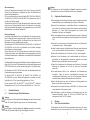
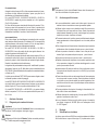
2 Technical Description
The series PILOT WA 900 is a simple modular system, which enables all possible
combinations required in ractice. There are two basic models, one with and the other
one without internal control. For this purpose there are two different quick-release
adapter plates which fit both models or can be converted accordingly.
Guns of series WA 900 can only be used in connection with an adapter plate. The
guns can alternatively be used in radial or circulation method. In order to incorporate
the guns in circulation mode, the assembled sealing pin (Pos. 30) needs to be
removed.
The models of the PILOT WA 900-Serie are an all-automatic air-controlled guns
operating in combination with a 3/2-way control valve

3938
With internal control:
Actuation of the 3/2-way control valve directs control air into the cylinder inside the
gun so as to open - in sequence - the atomizing air and the material input.
The shape of the spray is set on the gun with the models PILOT WA 900 / WA 920-
HVLP/ WA 940-HVLP
PLUS
/ WA 903-K and WA 923-HVLP-K using regulating screws
(Pos. 28 and 29).
If the control air through the 3/2-way valve is interrupted, compressed air remaining
in the cylinder chamber will first escape. The spring pressure of the piston spring
subsequently pushes the material needle to its original position, closes the material
supply and finally the spray air.
Without internal control:
The atomizer air (round and wide jet air) should first be switched on via an external
3/2-way control valve provided by the customer. Then the control air is opened via a
second 3/2 way valve, which presses both the piston and the material needle back
in order to open the material supply.
For the models PILOT WA 905/ WA 925-HVLP/ WA 945-HVLP
PLUS
/ WA 908-K and
WA 928-HVLP-K the shape of the spray jet is adjusted via the two customer supplied
compressed air regulators in the plant.
If the control air is interrupted by the 3/2-way control valve, spring pressure will move
the piston and the material needle back to their initial position and close the material
supply to the material nozzle. The atomizer air should then be switched off.
The material flow volume is on all models set via the material pressure and the cap
(item 26). The flow of material in the automatic spray gun series PILOT WA 900 can
also be manually opened by means of the drawbar (Pos. 27).
The spray guns of the PILOT WA 900 series can be connected to material pressure
tanks or pumping systems.
The models PILOT WA 920-HVLP/ WA 925-HVLP/ WA 923-HVLP-K and
WA 928-HVLP-K are pure low-pressure spray guns working with a spraying air
pressure of 0.7 bar at an intake air pressure of 3,3 bar.
With the models PILOT WA 940-HVLP
PLUS
bis WA 945-HVLP
PLUS
the intake air
pressure ranges from 3.0 to 3.3 bar for a spraying air pressure of 1.2 to 1.4 bar.
3 Safety Warnings
3.1 Safety Warning Symbols
Warning
This pictograph and the accompanying warning note „Warning“ indicate possible
risks and dangers for yourself. Possible consequences: Injuries of any kind.
Caution
This pictograph and the accompanying warning note „Caution“ indicate possible
damage to equipment. Possible consequences: Damage to equipment, workpieces,
etc.
Notice
This pictograph and the accompanying note „Notice“ indicate additional and useful
information to help you handling the spray gun with even greater confidence and
efficiency.
3.2 Generally Applicable Safety Precautions
► All applicable accident prevention rules and regulations as well as other recognis-
ed industrial safety and health rules and regulations must be observed at all times.
► Use the spray gun only in well-ventilated rooms. Fire, naked flames and smoking
are strictly prohibited within the working area. WARNING – during the spraying of
flammable materials (e.g. lacquers, adhesives, cleaning agents, etc.), there is an
increased risk to health as well as an increased risk of explosion and fire.
► You must ensure that the spray gun is properly earthed (grounded) either separa-
tely or in connection with the equipment with which it is being used (max. resistance
10
6
Ω).
► Before carrying out maintenance or servicing work, always ensure that the air and
material feed to the spray gun have been de-pressurised. Risk of injury!
► When spraying materials, do not place your hands or other parts of the body in
front of the pressurised nozzle or the spray gun. Risk of injury!
► Never point the spray gun at persons or animals. Risk of injury!
► Always observe the spraying and safety instructions given by the manufacturers
of the spraying material and the cleaning agent. Aggressive and corrosive
materials in particular can be harmful to health.
► Always wear hearing protection when using the gun or when in the vicinity of a
gun that is in use. The noise level generated by the spray gun is approx. 86 dB(A).
► Exhaust air containing particles (overspray) must be kept away from the working
area and personnel. In spite of these measures, always wear the regulation
breathing masks and protective overalls when using the gun. Airborne particles
represent a serious health hazard!
► After carrying out assembly or maintenance work, always ensure that all nuts,
bolts and screw connections have been fully tightened before the gun is used.
► Use only original replacement parts, since WALTHER can only guarantee safe
and fault-free operation for original parts.
► For further information on the safe use of the spray gun and the spraying
materials, please contact WALTHER Spritz- und Lackiersysteme GmbH,
D-42327 Wuppertal, Germany.
4 Assembly / Installation
4.1 Radial or circulation method
The spray guns series WA 900 arrive completely assembled from the factory. They
are by standard delivered with a sealing pin (Pos. 30).

4140
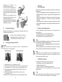
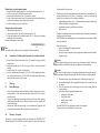
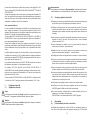
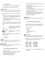
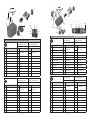
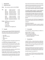
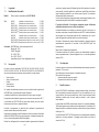
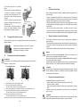
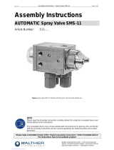
4.2 Mounting of Spray Gun
Install the gun in a suitable and stable mounting device as shown in the following
example:
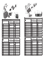
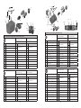
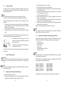
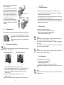
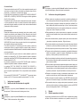
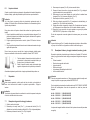
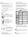
4.3 Connection of Input Lines
Warning
Make sure not to confuse the control and atomizing air connections -risk of injury.
1 = MATERIAL inlet fitting (G 1/4“) marked with 'M'
2 = FAN air inlet fitting wide jet (PU hose outer ø 8 mm) marked with 'F'
3 = CONTROL air inlet fitting (PU hose outer ø 6 mm) marked with 'C'
4 a = ATOMIZING air inlet fitting round-/ wide jet (PU hose outer ø 8 mm)
marked with 'A'
4 b = ATOMIZING air inlet fitting round jet (PU hose outer ø 8 mm)
marked with 'A'
The spray gun is now properly installed and connected and ready for operation.
4a
3
1
1
with internal control
2 4b
3
1
1
without internal control
1
For this purpose, use the two M 6 holes (1) (adaptor plate)
with a hole spacing of 33 mm.
Other mounting devices upon request.
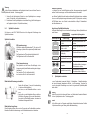
In this version the gun can only be used in
radial mode.
If you have decided on a circulation mode
adapter plate, you must remove the sealing
pin (Pos. 30). This opens a second material
channel.
Screw the spray gun on the adapter plate.
Use the two socket head cap screws
(Pos. 31) for this purpose.
The following work must be performed
before you can start operation of the spray
gun with adapter plate.
Sealing pin
(Pos. 30)
Radial method
Circulation method
5 Operational Handling
5.1 Safety Warnings
Please pay special attention to the following safety warnings prior to taking this spray
gun into operation!
• Wear proper respiratory protection masks and protective overalls, whenever you
are operating this spray gun. Air-borne particles represent a health hazard.
• Make sure to wear suitable haering protectors. The gun produces sound levels
of up to 86 dB (A) which may cause hearing defects.
• Open fires, naked lights and smoking prohibited in the working area. Spraying
of readily flammable media such as paints and adhesive compounds is always
accompanied by the risk of fire and explosion.
5.2 Starting / Stopping Requirements
The following requirements must be met before taking this spray gun into operation:
• control air must be available at the gun.
• atomizing air must be available at the gun.
• material pressure must be available at the gun.
Caution
The material pressure shall not exceed • 8 bar, as, otherwise, the functional reliabty
of the spray gun will suffer.
Adjust the control air pressure to • at least 4,5 bar, in order to operate the spray gun.
The operation of the spray gun can be started/stopped by way of the 3/2-way control
valve (see the Operating Instructions of the plant systems manufacturer).
Warning
It is important to remember that the spray gun must be relieved of all pressures
whenever work is terminated. Lines left in pressurized condition could burst, with
their contents likely to injure anybody present nearby.
5.3 Spray Pattern Test
Spray pattern tests should be performed whenever:
• the spray gun is taken into operation for the first time.
• the medium is changed.
• the spray gun was taken apart for servicing or repairs.
The spray pattern can be tested using a work piece sample, a sheet of metal, card-
board or paper.
Warning
Keep away from the front of the spray gun - imminent risk of injury.

4342
Warning
Make sure that nobody is present in the spraying zone when the gun is started
- imminent Risk of Injury.
1. Start the gun to produce a spray pattern sample (see 5.2. Starting/Stopping
Requirements).
2. Inspect the sample and readjust the settings of the gun as may be required (see
5.4 Spray Pattern Adjustments).
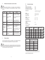
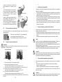
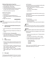
5.4 Spray Pattern Adjustments
The spray pattern of the of the series PILOT WA 900 can be adjusted as follows:
Adjusting the jet pattern
Adjustment of the material flow rate
Adjustment of the Material Pressure
This adjustment can only be made at the pump or the material pressure tank. Please
comply with the operating instructions and safety warnings issued by the manufac-
turers concerned.
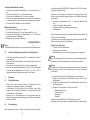
1
2
Turn cap (1) from the standard position
(= notch mark on the piston housing).
• to the inside in order to decrease the material flow
rate.
• to the outside in order to increase the material flow
rate.
The material flow through the nozzle can be perfor-
med without using atomizing air, when the drawbar
(2).
F
A
With internal control:
An optimum spray pattern can be regulated by using
adjustment screws 'F' (Fan air) and 'A' (Atomizing air).
The adjustment screw 'F' regulates the wide jet, the
adjustment screw 'A' regulates the round jet.
F
A
Without internal control:
The spray pattern is adjusted by a ressure regulator in the
plant (see operating instructions of plant systems manuf-
acturer).
The connection 'F' is for the wide jet,
the connection 'A' is for the round jet.
Adjustment of the Air Pressure
The air pressure is adjusted at the air pressure reducing valve of the compressor
system. Please comply with the operating instructions and safety warnings issued by
the manufacturer.
If you wish to change the spraying pattern beyond the adjustments outlined so far,
you must retool the spray gun (See 5.5 Retooling of Spray Gun).
WALTHER offers a great variety of air cap-/ material nozzle-/needle combinations for
this purpose.
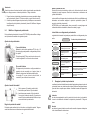
Correcting of Spray Pattern Imperfections
The following table shows what to do to correct a spray pattern:
Spray pattern
test
Fault Necessary adjustment
Swollen centre • Spray jet should be flatter
Swollen ends • Spray jet should be rounder
Coarse pearl effect • Increase wide jet air pressure
Unduly thin paint layer
in centre
• Decrease wide jet air pressure
Spray pattern is split in
the centre
• Increase nozzle diameter
• Reduce atomising air pressure
• Increase material pressure
Spray pattern is very
spherical
• Decrease material pressure
• Increase atomising air pressure
5.5 Retooling of Spray Gun
Combinations of air cap, material nozzle and needle, designed to match specific
spraying media tpyes and grades, form a unit - namely the nozzle insert assembly.
In order maintain the desired spray-finish quality standard always replace the
complete nozzle insert assembly.
Warning
Prior to retooling: Make sure that the spray gun is in unpressurized condition, i.e. all
air and material inputs must be shut off - if not, imminent risk of injury.
Note
In order to perform the following procedures please use the drawing at the beginning
of these operating instructions.
desired spray result

4544
Replacing air cap and material nozzle
1. Unscrew the fluted retaining ring (Pos. 1) from the front body section (Pos. 7).
2. Pull the air cap (item 2) from the front body section.
3. Unscrew the material nozzle (Pos. 3) from the front section.
4. Screw in the desired material nozzle (if necessary replace the sealing washer)
and mount the desired air cap to the front body section.
5. Screw the retaining ring on the front body.
Changing the material needle
1. Unscrew the drawbar (Pos. 27).
2. Unscrew the cap (Pos. 26) from the piston casing (Pos. 19).
3. Screw the drawbar into the material needle (Pos. 21) and pull the material
needle out of the piston casing.
Assembly takes place in reverse order.
Note
The needle setting is 98 mm from the needle tip to the driving bushing.
5.6 Conversion of adapter plate from radial to circulation method
1. Loosen the two cylinder head screws (Pos. 31) and take the spray gun off the
adapter plate.
2. Remove the sealing pin (Pos. 30) from the gun. (See 4.1 radial or circulation
method)
3. Screw the plug (Pos. 10) into the front section.
4. Insert the second material connection (V 00 101 01 003 for adapter plate alumi-
nium nickel coated at rear or V 21 900 20 003 for adapter plate stainless steel
lateral material connection) into the plate.
6 Cleaning
6.1 Safety Warnings
• Prior to any servicing and repair work: Make sure that the spray gun is in unpres-
surized condition, i.e. all air and material inputs must be shut off - if not, immi-
nent risk of injury.
• No open fires, naked light and smoking allowed in the work area. When spraying
readily flammable media such as cleaning solutions, there is an increased risk
of fire and explosion.
• Observe the safety warnings issued by the manufacturer. Aggressive and
corrosive media represents risks and hazards to personal health.
6.2 Cleaning - Complete
The spray gun must be regularly cleaned and lubricated with WALTHER PILOT
spray gun grease (V 00 000 00 001) in order to enhance its service life and ensure
the functionality of the spray gun.
Clean the gun only with cleaning solutions recommended by the manufacturer of the
spraying material used at the time. It is important to make sure that cleaning
solutions do not contain any of the following constituents:
• halogenated hydrocarbons (e.g. 1,1,1-trichloroethane, methylene chloride, etc.)
• acids and acidiferous cleaning solutions
• regenerated solvents (so-called cleaning dilutions)
• paint removers.
The above constituents cause chemical reactions with the electroplated components
resulting in corrosion damage.
WALTHER Spritz- und Lackiersysteme is not responsible for any damages resulting
from such treatment.
Clean the spray gun
• prior to each change of the spraying medium.
• at least once a week.
• as often as may be required by the spraying medium handled and the resultant
degree of fouling.
Caution
Never immerse the spray gun in solvent or any other cleaning solution. The functio-
nal reliability and efficiency of the gun can otherwise not be guaranteed.
Caution
Do not use any hard, pointed or sharp-edged objects when cleaning the spray gun.
Any damage of the precision-made parts are likely to affect your spraying results.
1. Dismantle the spray gun in accordance with 5.5 Retooling the Spray Gun.
2. Use a soft brush together with a compatible cleaning sulotion to clean the air cap
and nozzle.
3. Clean the remaining parts and the spray gun body with a suitable cloth and
cleaning solution.
4. Apply a thin film of the appropriate grease to the:
• sealing collar of the piston
• O-ring of the piston
• material control needle
• needle spring
Use WALTHER PILOT gun grease and a brush for this purpose.
The spray gun is then reassembled in reverse order.
98

4746
6.3 Cleaning - Routine
The spray gun need not necessarily be dismantled for cleaning if and when the
spraying medium is changed in regular intervals or upon termination of work (depen-
ding on the material used).
Note
Clean and lubricate the spray gun frequently in accordance with Chapter
6.2 Cleaning - Complete. This will ensure functional reliability of the spray gun.
The following requirements must be met before the routine cleaning work can be
performed:
1. The material tank must be clean and then be filled with a compatible cleaning
solution. Material pressure has to be available at the spray gun. The cleaning
solution should not be sprayed.
2. Take the spray gun into operation (see 5.2 Starting the Spray Gun).
3. Only take the spray gun out of service after it merely sprays clear cleaning
agent.
The material supply of the series PILOT WA 900 can be manually released so that it
is not necessary to operate the complete spraying system.
All pressures should then be removed from the complete spraying system until the
next operation.
7 Repairs / Replacements
Warning
Prior to any repairs / replacements: Make sure that the spray gun is in unpressurized
condition, i.e. all air and material inputs must be shut off - if not, imminent risk of
injury.
Note
Please use the drawing at the beginning of these operating instructions to perform
the following procedures.
7.1 Replacement of defective Needle Packing
1. Remove all pressures from the gun.
2. Unscrew the front body section (Pos. 7) and the piston casing (Pos. 19) from the
adapter plate by loosening two cylinder head screws (Pos. 31).
1. Pull back the draw bar of the spray gun. The material
inlet is now open and both material duct and material
nozzle will be cleaned.
2. Do not let go of the drawbar until clear cleaning soluti-
on emerges from the nozzle.
3. Unscrew the drawbar (Pos. 27) from the gun.
4. Unscrew the cap (Pos. 26) from the piston casing.
5. Screw the drawbar into the material needle (Pos. 21) and pull the material need-
le out of the piston casing.
6. Unscrew the front body section from the piston casing (Pos. 19) by loosening
four socket head cap screws (Pos. 5).
7. Unscrew the packing screw (Pos. 12).
8. Remove the packing spring (Pos. 11) (replace if damaged) and the washer
(Pos. 10) from the screw hole.
9. Pull out the needle seal packing (Item 9) with an auxilliary tool. Use a strong wire
on which one end is bent making a small hook.
10. Grease the new needle packing with WALTHER PILOT spray gun grease and
insert it into the front body section.
Installation of the remaining parts is performed in reverse order.
Note
Never reinstall a used needle seal packing (Item 9) as otherwise the functional
sealing reliability of the spray gun will suffer.
7.2 Replacement of Nozzles, Needles, Springs and Seals
Dismantle the spray gun in accordance with Chapter 5.5 Repalcement of Material
Control Nozzle and Needle, if the following components have to be replaced:
• Material Nozzle
• Pressure of the Piston
• Material Needle*
• Needle Spring*
• Flat mechanical seal of the Piston*
• O-Ring of the Piston*
Note
Components marked * must be greased with WALTHER PILOT spray gun grease
before installation in the gun body.
WALTHER Spritz- und Lackiersysteme repair kits are available for PILOT WA 900
series spray guns including all wearing parts:
Parts No.: V 16 209 00 . . 3 (WA 900 / WA 905)
Parts No.: V 16 209 20 . . 3 (WA 920 / WA 925)
Parts No.: V 16 209 40 . . 3 (WA 940 / WA 945)
Parts No.: V 16 219 03 . . 3 (WA 903 / WA 908)
Parts No.: V 16 219 23 . . 3 (WA 923 / WA 928)
Wearing parts are also shown in the listing of replacement parts (in bold face).

4948
8 Troubleshooting and Corrective Action
Warning
Prior to any servicing and repair work: Make sure that the spray gun is in unpressu-
rized condition, i.e. all air and material inputs must be shut off - if not, imminent risk
of injury.
Fault Cause Remedy
Gun is dripping
Material nozzle or needle
fouled
Material nozzle or needle
damaged
Packing screw (Item 12) too
tight
see 5.5 Retooling the Spray Gun
and cleaning
see 5.5 Replacing Material
Control Nozzle or Needle
Loosen packing screw in slightly
with a screw driver
Gun fails to
open
Control air pressure too low
Increaese control air pressure to
at least 4.5 bar
Material leaks
from leakage
boring
Needle packing leaks
Packing screw too loose
see 7.1 Replacing Needle
Packing
Tighten packing screw (Item 12)
in slightly with a screwdriver
Spray jet pulsa-
ting or unsteady
Level in material tank too
low
Top-up material level (see opera-
ting instructions of plant systems
manufacturer)
9 Disposal of Cleaning / Servicing Substances
Disposal of any such substances must be in accordance with all applicable local and
national regulations, directives and laws.
Warning
Pay special attention to all processing specifications and safety warnings issued by
the manufacturers of spraying and cleaning media. The improper disposal of any
toxic waste material represents a serious threat to the environment, i.e. to the health
of mankind and animal life.
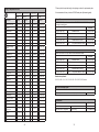
10 Specification Data
Weight
Automatic Spray Guns with internal control: 520 g
Automatic Spray Guns without int. control: 490 g
Adaptor plate Aluminium, nickel coated: 195 g
Adaptor plate stainless steel: 260 g
Nozzle Sizes: • 0,3 • 0,5 • 0,8 • 1,0 • 1,2 • 1,5 • 1,8
• 2,0 • 2,2 • 2,5 • 3,0 • 3,5 mm ø
Connections
Atomizing Air: PU hose outer ø 8 mm
Control Air: PU hose outer ø 6 mm
Material Inlet: G 1/4“
Pressure Ranges
Control Air: mind. 4,5 bar
Material pressure: max. 8 bar
Atomizing Air: max. 8 bar
max. Operating Temperature
of Spray gun 80 °C
Sound Level
(measured at a distance
of 1 m from the spray gun) 86 dB (A)
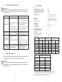
Air Consumption:
PILOT WA 900
PILOT WA 905
PILOT WA 920 HVLP*
PILOT WA 925 HVLP*
PILOT WA 940 HVLP
PLUS
**
PILOT WA 945 HVLP
PLUS
**
Air input of the
spray gun
round jet wide jet round jet wide jet round jet wide jet
1 bar 100 l/min 120 l/min 120 l/min 126 l/min 114 l/min 121 l/min
2 bar 165 l/min 183 l/min 188 l/min 203 l/min 172 l/min 188 l/min
3 bar 230 l/min 260 l/min 265 l/min 283 l/min 237 l/min 259 l/min
4 bar 290 l/min 325 l/min 332 l/min 358 l/min 303 l/min 325 l/min
4,5 bar 321 l/min 358 l/min 372 l/min 400 l/min 330 l/min 360 l/min
5 bar 345 l/min 395 l/min 414 l/min 441 l/min 365 l/min 400 l/min
PILOT WA 903-K / PILOT WA 908-K
PILOT WA 923-HVLP-K / PILOT WA 928-HVLP-K
Air input of the spray
gun
round jet wide jet
1 bar 75 l/min 145 l/min
2 bar 135 l/min 230 l/min
3 bar 190 l/min 325 l/min
4 bar 240 l/min 420 l/min
4,5 bar 295 l/min 510 l/min
5 bar 345 l/min 650 l/min
* The atomizing air pressure is 0,7 bar with an air input pressure of 3,3 bar.
** The atomizing air pressure is 1,3 bar with an air input pressure of 3,3 bar.
Right to effect technical changes reserved.
Page is loading ...
Page is loading ...
Page is loading ...
Page is loading ...
Page is loading ...
Page is loading ...
Page is loading ...
Page is loading ...
Page is loading ...
Page is loading ...
Page is loading ...
Page is loading ...
Page is loading ...
Page is loading ...
Page is loading ...
Page is loading ...
Page is loading ...
Page is loading ...
Page is loading ...
Page is loading ...
Page is loading ...
Page is loading ...
Page is loading ...
Page is loading ...
Page is loading ...
Page is loading ...
Page is loading ...
Page is loading ...
Page is loading ...
Page is loading ...
Page is loading ...
Page is loading ...
Page is loading ...
Page is loading ...
-
 1
1
-
 2
2
-
 3
3
-
 4
4
-
 5
5
-
 6
6
-
 7
7
-
 8
8
-
 9
9
-
 10
10
-
 11
11
-
 12
12
-
 13
13
-
 14
14
-
 15
15
-
 16
16
-
 17
17
-
 18
18
-
 19
19
-
 20
20
-
 21
21
-
 22
22
-
 23
23
-
 24
24
-
 25
25
-
 26
26
-
 27
27
-
 28
28
-
 29
29
-
 30
30
-
 31
31
-
 32
32
-
 33
33
-
 34
34
-
 35
35
-
 36
36
-
 37
37
-
 38
38
-
 39
39
-
 40
40
-
 41
41
-
 42
42
-
 43
43
-
 44
44
-
 45
45
-
 46
46
-
 47
47
-
 48
48
-
 49
49
-
 50
50
-
 51
51
-
 52
52
-
 53
53
-
 54
54
-
 55
55
-
 56
56
-
 57
57
-
 58
58
-
 59
59


WALTHER PILOT WA 920-HVLP Operating instructions
- Type
- Operating instructions
- This manual is also suitable for
Ask a question and I''ll find the answer in the document
Finding information in a document is now easier with AI
in other languages
Related papers
-
WALTHER PILOT V 20 340 Operating instructions
-
-
-
-
-
-
-
-
-
Other documents
-
Peerless ACC315 Owner's manual
-
Parkside PFS 280 A1 Operating instructions
-
Parkside 109910 Operation and Safety Notes
-
-
Bartscher 110.138 Owner's manual
-
Parkside PHP 500 B2 Owner's manual
-
-
-
 Walther Systemtechnik SMS-11 Assembly Instructions Manual
-
Sagola Pistola mixta 4041 mix Owner's manual
