Page is loading ...

v C 201110
I
MANUALE D’ISTRUZIONE
E
ISTRUCCIONES DE USO
GB
INSTRUCTION MANUAL
F
MODE D’EMPLOI
P
INSTRUÇÕES DE USO
EURO24M1
[
code
E103]
ATTENZIONE!! Prima di effettuare l’installazione, leggere attentamente questo manuale.
La VDS declina ogni responsabilità in caso di non osservanza delle normative vigenti.
¡ATTENCIÓN!! Antes de efectuar la instalacion, lea attentamente el presente manual. La Empresa VDS no asumirà
responsabilidad alguna en caso de inobservancia de las normas vigentes en el pais donde se lleva a cabo la installacion
WARNING!! Before installing, thoroughly read this manual that is an integral part of this Kit. VDS declines any responsa-
bilità in the event curret stadards in the country of installation are not comlplied with.
ATTENTION!! Avant d’effectuer l’installation, lire attentivement le présent manuel qui fait partie intégrante de cet embal-
lage. La société VDS décline toute responsabilità en cas de non respect des normes en viguer.
ATENÇÃO!! Antes de instalar, leia este manual. VDS isenta de qualquer responsabilidade pelo não cumprimento com
os regulamentos.
Apparecchiatura di comando 1 Motore 24Vdc
Cuadro electronico para uno motores 24Vdc
Elettronic control panel for one 24Vdc motor
Dispositif de commande 1 moteur 24Vdc
Central de controle de 1 motor 240Vdc
ELETTRONIC DIVISION

OPTIONS SELECTOR
The maneuvers are executed through the Alternative button (Test button on the motherboard, or Alternative switch terminals, or by radio card).
The maneuvers ends for one of the following conditions: activation of the corresponding end switchs orby the end of operating time.
If during the opening operation is given an order, the action is stoped and do not run the closing.
Stop button activation causes immediate stop of the maneuver, requiring an order for the resumption of it.
Activation os safety switch input during closing, inverts it and goes to open position.
Input battery alimentation.
Garage light is activated during 0.5 sec. before starting the opening operation and is turned off 2 sec. after it.
Courtesy light at the opening (if allowed) flashes slowly, and on closing flashes quickly. In open position courtesy light is ON.
Drive power regulation selected in R. FORCE, it will be applied after 2 sec. Of the maneuvre.
OPERATING INSTRUCTIONS
EURO24M1
Instruction Manual
RADIO CARD
WIRELESSBAND
RADIO CARD
LOOP DETECTORLOOP DETECTOR
PHOTOCELL INHIBITOR
ELECTRO LOCK
GARAGE LIGHT
PRE FLASHING
TRAFFIC LIGHT
THREEPHASE SWITCH
EMERGENCY STOP
SAFETY EDGE INPUT
FUSES
VARISTOR
ZENER DIODES
PHOTOCELL INPUT
DEAD MAN
PHOTOCELL TEST
SAFETY EDGE TEST
OPEN CLOSE LIMIT SWITCH
ALTERNATIVE BUTTON
PRESSURE WAVE SWITCH
AUTOMATIC DOWN TIME (TEMPORIZER)
OPENING TIME (TEMPORIZER)
CLOSING TIME (TEMPORIZER)
DRIVE POWER (TEMPORIZER)
DEPHASE( DRIVE 1 & 2 (TEMPORIZER)
CLOSE SWITCH
OPEN SWITCH
STOP BUTTON
BUFFER CLOSING
CLOSE BY SAFETY CONTACT
AUTOMATIC CLOSING
INHIBITION STOP ON OPENING
DOUBLE TIME
DIGITAL TIME
HOURLY IMPULSE
PARTIAL / TOTAL INVERSION TIMES
AUTOMATIC CLOSING FOR LIMIT SWITCH
AUTOMATIC FRECUENCY AGILITY (Bridge S.)
POWER SUPPLY FOR ACCESSORIES
FREE TENSION INPUT
CONTACT 0V
RADIO PROGRAMMING BRIDGE SELECTOR
FRECUENCY CHANNEL SELECTOR
230V
380v
433MHz
868MHz
1 DRIVE
2 DRIVE
WIRELESSBAND RECEIVER
ACCESSORIES SAFETY
SETTINGS
•
OPTIONAL
NOT AVAILABLE
STANDARD
•
•
•
WARNING!!
AN ACCESSIBLE SWITCH, TO TURN OFF THE EQUIPMENT MUST BE INSTALLED FOR SYSTEMS THAT
ARE ALWAYS CONNECTED.
BEFORE INSTALLING MAKE SURE THE SUPPLY VOLTAGE IS SWITCHED OFF.
In order to program functions the control panel should be in a stable state with the door closed.
Option number 3 must be turned OFF. If we want buffer closing I7 must be turned ON and if we have an encoder DIP switch number 8 must be turned ON too.
Push button PROG TIEMPOS for 1,5 secs. The red LED will light up indicating that the panel is ready for time programming. Now we can proceed. In order to stop
programming press button PROG for 1,5 secs again with the door in 'resting' position; the process requires that a full opening and closing cycle is completed.
To program working times with pedestrian button press PROG button for 1 5s Let and press the button for 1.5s and programming LED will turned ON. With pedestrian
button we will start the programming time function
Programming times process
1) The door must be closed. Activate as described above. The red LED lights up.
2) Push "START" button to open the door.
Pushing "START" again will stop the door and will memorize the time of opening. If opening is finalized by limit switch open (LSO), the programme will memorise times +
4 sec.
3) Once the door is open, the closing time will be memorized automatically until the closing operation has begun.
4) Push"START" button to close the door.
I7 OFF - Pushing "START” again will stop the door and memorize the closing time. If closing is finalized by limit switch (LSC), the programme will memorise
times + 4 sec.
I7 ON - Pushing "START” button again, drive reduce the speed (buffer closing), and pressing it again, the manoeuvre will stop and closing time, and buffer
closing will be memorized. If the manouvre is finalized by limit switch open (LSO), the programme will memorise times + 4 sec.
5) Upon completing a full cycle of the door programming will be automatically finalized.
The maximum memorization time is 2 minutes, if you wait more, this limit will be memorized.
DIGITAL PROGRAMMING of open, close & automatic close.
GB
OPTION
OPTION
ON Door closes automatically after waiting the a.c. time.
OFF Door does not close automatically.
OPTION
ON Alternative button stops and invert at close. Disable stop opening.
OFF Alternative button stops.
OPTION
ON Invert drive direction.
OFF Normal drive direction.
OPTION 5 - Pneumatic Band with Stop Options
ON Input Cseg1 works like security band, stopping opening and closing.
OFF Input Cseg1 works like security band, stopping the closing and stop &
inverts 2 sec. in the opening.
OPTION 6 - Flashing Light
ON Flashing
OFF Fixed
OPTION 7 - Buffer Closing
ON Drive reduce it’s speed at the end of opening & closing.
OFF No buffer.
OPTION 8 - Enconder Yes/No
ON Enable encoder input.
OFF Disable encoder input.
1 - Garage Doors / Sliding Gate
ON Garage.
OFF Sliding.
2 - Automatic Closing
3 - Door Stop & Inverts and Disable Stop Opening
4 - Drive Direction
OPTIONS SELECTOR

Alimentation 24V AC
Motor Tension 24V DC
Motor Current Max. 2,5A
Output Accessory Alimentation
Light Contact N.O.
Flash Contact N.O.
2 minutes
3 sec. a 2 minutes
Radio Card
24V DC 150mA
Working Time
Automatic Closing Time
Internal
Working Temperature -20 to 70ºC
TECHNICAL SPECIFICATIONS
FLASH
LIGHT
LIGHT
6 7
ALIMENTATION
MOTOR
PUSH
BUTTONS
TERMINALS
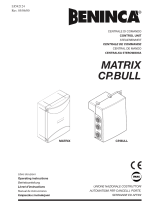
STANDARD CONTROL PANEL SET UP
TERMINAL DESCRIPTION
REGULATIONS
STRENGTH MOTOR REGULATION (GREEN)
Regulation the strength of motor.
Rotate LEFT to decrease and
rotate RIGHT to increase.
Regulates drive power
Turn LEFT to decrease and
RIGHT to increase
DRIVE POWER (RED)
+
-
+
-
ACCESSORIES
POWER SUPPLY
EURO24M1
1 2 3
4 5
6 7 8 9
10 11 12 13
14
15
16
17
18 19 20
21
23 262524
2827
22
24V
10 11
LIMIT
SWITCH
SAFETY
SECURITY COSTA
& PHOTOCELL
12
13 14
ANTENNA
ANTENNA
27 28
15
16 17
LSO - OPEN
LSC - CLOSE
ENCODER
MOTOR
M
2
1
ENCODER
4 5
3
S
Vcc
START
BUTTON
PEDES.
BUTTON
20 21
22
24V
23 24
BATTERY
25 26
BATTERY
STOP
18 19
STOP
Instruction Manual
FLASH
8 9
GB
/